EP2917509B1 - Ensemble chambre de combustion modulaire instantané pour turbine à gaz industrielle et procédé pour installation - Google Patents
Ensemble chambre de combustion modulaire instantané pour turbine à gaz industrielle et procédé pour installation Download PDFInfo
- Publication number
- EP2917509B1 EP2917509B1 EP13785793.4A EP13785793A EP2917509B1 EP 2917509 B1 EP2917509 B1 EP 2917509B1 EP 13785793 A EP13785793 A EP 13785793A EP 2917509 B1 EP2917509 B1 EP 2917509B1
- Authority
- EP
- European Patent Office
- Prior art keywords
- combustor
- assembly
- axis
- case
- gas turbine
- Prior art date
- Legal status (The legal status is an assumption and is not a legal conclusion. Google has not performed a legal analysis and makes no representation as to the accuracy of the status listed.)
- Not-in-force
Links
- 238000009434 installation Methods 0.000 title description 14
- 238000000034 method Methods 0.000 title description 2
- 238000003780 insertion Methods 0.000 claims description 27
- 230000037431 insertion Effects 0.000 claims description 27
- 230000033001 locomotion Effects 0.000 claims description 17
- 230000007704 transition Effects 0.000 claims description 16
- 230000008878 coupling Effects 0.000 claims description 9
- 238000010168 coupling process Methods 0.000 claims description 9
- 238000005859 coupling reaction Methods 0.000 claims description 9
- 230000000712 assembly Effects 0.000 claims description 8
- 238000000429 assembly Methods 0.000 claims description 8
- 238000010276 construction Methods 0.000 description 3
- 230000004323 axial length Effects 0.000 description 2
- 238000007689 inspection Methods 0.000 description 2
- 230000013011 mating Effects 0.000 description 2
- 238000013519 translation Methods 0.000 description 2
- 238000003491 array Methods 0.000 description 1
- 210000000078 claw Anatomy 0.000 description 1
- 238000002485 combustion reaction Methods 0.000 description 1
- 238000004891 communication Methods 0.000 description 1
- 239000000446 fuel Substances 0.000 description 1
- 230000003116 impacting effect Effects 0.000 description 1
- 238000011065 in-situ storage Methods 0.000 description 1
- 230000002452 interceptive effect Effects 0.000 description 1
- 238000012423 maintenance Methods 0.000 description 1
- 238000012544 monitoring process Methods 0.000 description 1
- 230000003252 repetitive effect Effects 0.000 description 1
Images


Classifications
-
- F—MECHANICAL ENGINEERING; LIGHTING; HEATING; WEAPONS; BLASTING
- F02—COMBUSTION ENGINES; HOT-GAS OR COMBUSTION-PRODUCT ENGINE PLANTS
- F02C—GAS-TURBINE PLANTS; AIR INTAKES FOR JET-PROPULSION PLANTS; CONTROLLING FUEL SUPPLY IN AIR-BREATHING JET-PROPULSION PLANTS
- F02C7/00—Features, components parts, details or accessories, not provided for in, or of interest apart form groups F02C1/00 - F02C6/00; Air intakes for jet-propulsion plants
-
- B—PERFORMING OPERATIONS; TRANSPORTING
- B23—MACHINE TOOLS; METAL-WORKING NOT OTHERWISE PROVIDED FOR
- B23P—METAL-WORKING NOT OTHERWISE PROVIDED FOR; COMBINED OPERATIONS; UNIVERSAL MACHINE TOOLS
- B23P19/00—Machines for simply fitting together or separating metal parts or objects, or metal and non-metal parts, whether or not involving some deformation; Tools or devices therefor so far as not provided for in other classes
-
- F—MECHANICAL ENGINEERING; LIGHTING; HEATING; WEAPONS; BLASTING
- F01—MACHINES OR ENGINES IN GENERAL; ENGINE PLANTS IN GENERAL; STEAM ENGINES
- F01D—NON-POSITIVE DISPLACEMENT MACHINES OR ENGINES, e.g. STEAM TURBINES
- F01D25/00—Component parts, details, or accessories, not provided for in, or of interest apart from, other groups
- F01D25/28—Supporting or mounting arrangements, e.g. for turbine casing
- F01D25/285—Temporary support structures, e.g. for testing, assembling, installing, repairing; Assembly methods using such structures
-
- F—MECHANICAL ENGINEERING; LIGHTING; HEATING; WEAPONS; BLASTING
- F23—COMBUSTION APPARATUS; COMBUSTION PROCESSES
- F23R—GENERATING COMBUSTION PRODUCTS OF HIGH PRESSURE OR HIGH VELOCITY, e.g. GAS-TURBINE COMBUSTION CHAMBERS
- F23R3/00—Continuous combustion chambers using liquid or gaseous fuel
- F23R3/28—Continuous combustion chambers using liquid or gaseous fuel characterised by the fuel supply
- F23R3/283—Attaching or cooling of fuel injecting means including supports for fuel injectors, stems, or lances
-
- F—MECHANICAL ENGINEERING; LIGHTING; HEATING; WEAPONS; BLASTING
- F23—COMBUSTION APPARATUS; COMBUSTION PROCESSES
- F23R—GENERATING COMBUSTION PRODUCTS OF HIGH PRESSURE OR HIGH VELOCITY, e.g. GAS-TURBINE COMBUSTION CHAMBERS
- F23R3/00—Continuous combustion chambers using liquid or gaseous fuel
- F23R3/42—Continuous combustion chambers using liquid or gaseous fuel characterised by the arrangement or form of the flame tubes or combustion chambers
- F23R3/60—Support structures; Attaching or mounting means
-
- F—MECHANICAL ENGINEERING; LIGHTING; HEATING; WEAPONS; BLASTING
- F05—INDEXING SCHEMES RELATING TO ENGINES OR PUMPS IN VARIOUS SUBCLASSES OF CLASSES F01-F04
- F05D—INDEXING SCHEME FOR ASPECTS RELATING TO NON-POSITIVE-DISPLACEMENT MACHINES OR ENGINES, GAS-TURBINES OR JET-PROPULSION PLANTS
- F05D2230/00—Manufacture
- F05D2230/60—Assembly methods
- F05D2230/68—Assembly methods using auxiliary equipment for lifting or holding
-
- F—MECHANICAL ENGINEERING; LIGHTING; HEATING; WEAPONS; BLASTING
- F23—COMBUSTION APPARATUS; COMBUSTION PROCESSES
- F23R—GENERATING COMBUSTION PRODUCTS OF HIGH PRESSURE OR HIGH VELOCITY, e.g. GAS-TURBINE COMBUSTION CHAMBERS
- F23R2900/00—Special features of, or arrangements for continuous combustion chambers; Combustion processes therefor
- F23R2900/00017—Assembling combustion chamber liners or subparts
-
- Y—GENERAL TAGGING OF NEW TECHNOLOGICAL DEVELOPMENTS; GENERAL TAGGING OF CROSS-SECTIONAL TECHNOLOGIES SPANNING OVER SEVERAL SECTIONS OF THE IPC; TECHNICAL SUBJECTS COVERED BY FORMER USPC CROSS-REFERENCE ART COLLECTIONS [XRACs] AND DIGESTS
- Y10—TECHNICAL SUBJECTS COVERED BY FORMER USPC
- Y10T—TECHNICAL SUBJECTS COVERED BY FORMER US CLASSIFICATION
- Y10T29/00—Metal working
- Y10T29/49—Method of mechanical manufacture
- Y10T29/49316—Impeller making
- Y10T29/4932—Turbomachine making
- Y10T29/49323—Assembling fluid flow directing devices, e.g., stators, diaphragms, nozzles
Definitions
- the invention relates to combustors for industrial gas turbines, and more particularly modular drop-in combustors that are preassembled in conformity with assembly and function specifications prior to installation into an industrial gas turbine.
- Known industrial gas turbines utilize replaceable combustors with flanged connections to access ports in the combustor case.
- a generally annular-shaped combustor basket has an open tip portion distal the combustor flange that is inserted in nesting fashion into a corresponding combustor transition along an insertion path that is coaxial with the centerlines of the respective access port, combustor basket and transition opening. Insertion is often performed with cranes and/or block and tackle gear to hold combustor weight, in conjunction with human alignment of the combustor basket with its receiving receptacle within the combustor case.
- the combustor length is much greater than radial clearance between the combustor basket outer circumference and other turbine components that are inside or outside the combustor case.
- a small yaw deviation of the combustor from the desired insertion path may result in inadvertent impact contact between the combustor and another turbine component--possibly resulting misalignment of combustor internal components (e.g., injectors, instruments, swirlers, nozzles, venturi, etc.) out of conformance with alignment and function specifications.
- injectors, instruments, swirlers, nozzles, venturi, etc. out of conformance with alignment and function specifications.
- Fully assembled combustor weight of over 1200 pounds (545 kg) further complicates precise combustor alignment during installation, especially if alignment is primarily performed by human operators.
- a combustor handling tool and combustor installation method that facilitate alignment and insertion of heavy pre-assembled combustors, preferably under automatic control, with repeatable manipulation steps.
- a combustor handling tool can remain permanently installed proximal the combustor case access ports for use as needed, or easily transported to and reassembled at various job sites by repair personnel.
- EP 2 070 663 A1 discloses a mounting arrangement for mounting burners and transition pieces in a gas turbine.
- the mounting arrangement comprises a pair of mounting devices.
- Each mounting device comprises a column lift, and a gripper arm arranged on the column lift.
- the gripper arm includes a holder equipped with a fastening element.
- the fastening element fastens a burner or transition piece to the holder.
- Each mounting device provides three translation degrees of freedom and at least two orientation degrees of freedom for a burner or transition piece fastened to the fastening element of the mounting device.
- a preferred feature of the present invention is specified in claim 2 of the set of two claims.
- a multi-axis motion combustor handling tool in the combustor service zone preferably under automatic control, is coupled to each combustor and facilitates precise alignment along the insertion path.
- Automatic control facilitates consistent repetitive combustor installation and removal by executing a sequence of stored pre-determined manipulation steps.
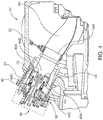
- FIG. 1 shows an industrial gas turbine 20 of the present invention that includes compressor section 22, combustor section 24 and turbine section 26.
- the turbine 20 has a combustor service zone 28, depicted in dashed lines, in which all piping, wiring, etc. is removable for clear access to the combustor case 30 and the combustor assemblies 40.
- each combustor assembly 40 has a mounting flange 42 that is coupled to the combustor case 30 access ports 32 by an intermediate spool piece 34 and circular arrays of fasteners 36, 38.
- the mounting flange 42 also has threaded apertures 44 four coupling to the combustor handling tool (CHT) of FIGs. 7-10 .
- CHT combustor handling tool
- the combustor assembly 40 is preassembled and inspected for conformance with assembly and functional specifications prior to installation in the combustor case 30.
- Preassembled components forming the combustor assembly 40 include externally mounted fuel injectors and instrumentation 46, of known operation and construction.
- the combustor basket 48 is of generally annular hollow construction, and houses swirlers 49A as well as venturi 49B and combustion nozzles 49C.
- the tip 48A of the combustor basket 48 that is distal the combustor mounting flange 42 slidably mates with a corresponding combustor transition 60.
- the combustor basket tip 48A outer circumference conforms generally to the transition 60 inner diameter.
- the combustor basket outer circumference 48B has relatively tight radial clearance within the corresponding access port 32 inner circumference of approximately 1 inch (25mm), compared to an approximate axial length from the combustor mounting flange 42 to the combustor basket tip 48A of at least 24 inches (600mm).
- combustor assembly 40 ratio of radial clearance to axial length is relatively small (at least approximately 0.04), slight yawing deviations of the combustor relative to its insertion path that is established in the axial centerline between the access port 32 and transition 60 inner circumferences may cause inadvertent combustor assembly contact with turbine 20 internal components. Any such internal contact may inadvertently cause the combustor assembly 40 damage or misalignment that may cause it to deviate from alignment and/or functional specifications.
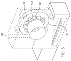
- the open, uncluttered combustor service zone 28, shown in FIGs. 1 and 5 prevents combustor assembly 40 damage while being aligned along the insertion path into the access port 32.
- the service zone 28 there are no turbine external components interfering with combustor assembly maneuvering.
- yawing misalignment deviations from the desired insertion path during combustor assembly 40 insertion into the combustor case 30 can cause damage.
- Embodiments of the present invention include a combustor handling tool (CHT) 80, shown in FIGs. 6-10 , that facilitates proper alignment and insertion of the relatively heavy combustor assembly 40 into its corresponding combustor case access port 32 in the combustor service zone 28 that is associated with gas turbine 20.
- the CHT 80 includes a right support column 82, for servicing combustor assemblies on the right side of the combustor case 30 and a left support column 84, for servicing combustor assemblies on the left side of the combustor case 30.
- separate mirror image combustor handling tools are dedicated to the respective right and left support columns 82, 84, but it is also possible to share CHT components for use on either side of the turbine 20.
- the CHT 80 for the right column 82 is shown.
- a mirror image may be affixed to the left column.
- the right support column 82 is selectively or permanently coupled to the turbine 20 pad floor structures by foundation mounting plate 83. It is possible to move the CHT 80 and its support column 82 from facility to facility for field service, but it is preferable to leave at least one CHT permanently at a facility.
- a motorized or hydraulic crane drive 86 is affixed to the column 82 to provide power for moving the multi-axis CHT 80.
- the crane drive 86 is under control of controller 87.
- each range of motion of CHT 80 or clusters of motion ranges may be driven by separate drives under control of controller 87 or a plurality of inter-communicating controllers.
- the lifting platform 88 provides CHT vertical elevation motion in the Z axis (shown).
- a combustor alignment platform 90 provides gross left-right (Y axis) motion by first slider 92, second slider 94, and third slider 96.
- Gross fore-aft (X axis) motion for insertion of the combustor assembly 40 into the combustor case access port 32 is facilitated by fourth and fifth sliders 106, 108.
- Fine translation motion for final combustor assembly 40 movement for example for centering the combustor 40 assembly concentrically within the access port 32 and transition 60 along insertion path I, is provided by slider 110 in the Z axis and slider 112 in the in the Y axis.
- the CHT 80 also facilitates rotational motion about the three coordinate axes.
- Turret assembly 100 provides pan or sweep rotation about the Z axis
- turret assembly 104 provides tilt or inclination/declination rotation about the Y axis
- hub 114 provides rotational about the X axis (for example for aligning combustor hub 42 bolt pattern with that of the spool piece 34 for subsequent insertion of the fasteners 38.
- hub 114 retains a plurality of grippers 120 that are coupled to apertures 44 in the combustor mounting flange 42 with threaded fasteners.
- Other types of known mechanical coupling devices may substituted for threaded fasteners and apertures 44 in the mounting flange 42, including by way of example hydro-mechanical or electro-mechanical gripper claws and mating structures in the mounting flange 42, mating keys/keyways or pins/apertures, etc.
- the CHT 80 is inserting a combustor assembly 40 into combustor access port 32A, that is oriented at approximately the 1 o'clock radial position in the combustor case 30 (see also FIG. 5 ).
- the CHT 80 aligns the combustor assembly 40 concentrically with the insertion path I, which needed to insert it into access port 32A and the awaiting corresponding transition 60, without inadvertently impacting the combustor basket 48 or other combustor assembly components with other turbine components within the combustor case 30.
- the CHT 80 motions are controlled by controller 87, which may be a programmable logic controller or a personal computer that utilizes a processor and operating system that accesses a stored instruction set.
- the controller 87 preferably stores a set of CHT 80 motion instructions needed to align and insert combustor assemblies 40 with each individual turbine access port 32 within reach of the CHT.
- the CHT 80 is capable of inserting all combustor assemblies 40 into access ports on the right side of turbine 20, and a mirror image CHT coupled to the left support column 84 inserts combustor assemblies 40 into access ports 32 on the left side of turbine 20.
- Motion instruction sets stored in the controller 87 are derived from virtual and/or actual CHT 80 multi-axis manipulation.
- a motion instruction set that successfully aligns and installs/retracts combustor assemblies 40 in combustor case access ports 32 is stored in the controller 87 and may be downloaded to other controllers. If needed, individual motion instruction sets may be modified to conform to alignment variations needed at different gas turbine installations.
- the controller 87 may be in wired or wireless communication with a network 87A, such as a power plant local area network or the Internet, for remote monitoring of combustor assembly installation and for receipt of updated or new motion instruction sets.
Landscapes
- Engineering & Computer Science (AREA)
- Mechanical Engineering (AREA)
- General Engineering & Computer Science (AREA)
- Chemical & Material Sciences (AREA)
- Combustion & Propulsion (AREA)
- Turbine Rotor Nozzle Sealing (AREA)
- Gas Burners (AREA)
Claims (2)
- Système de turbine à gaz industrielle, comprenant :une turbine à gaz (20) comportant des sections formant compresseur (22), dispositif de combustion (24) et turbine (26) ;la section formant dispositif de combustion (24) comportant un carter (30) de dispositif de combustion définissant une pluralité de paires correspondantes respectives d'orifices d'accès (32) de dispositif de combustion alignés en un ensemble circulaire, et de conduits de transition (60) dans le carter (30) de dispositif de combustion qui sont alignés coaxialement suivant des voies d'insertion (I) respectives ;une pluralité d'ensembles formant dispositifs de combustion insérables modulaires préassemblés (40) correspondant à chacune des paires correspondantes d'orifices d'accès (32) de dispositif de combustion et de conduits de transition (60), comportant une bride de montage (42) adaptée en vue de son couplage à l'orifice d'accès (32) de dispositif de combustion et un panier (48) de dispositif de combustion adapté en vue de son couplage coulissant au conduit de transition (60), etune zone (28) de servitude de dispositifs de combustion à proximité du carter (30) de dispositif de combustion, permettant l'insertion à coulissement de chaque ensemble formant dispositif de combustion (40) dans l'orifice d'accès (32) et le conduit de transition (60) lui correspondant suivant la voie d'insertion (I) lui correspondant sans contact avec d'autres composants du système de turbine,étant entendu que le système comprend un outil motorisé (80) de manutention multiaxiale de dispositif de combustion orienté dans la zone (28) de servitude de dispositifs de combustion, adapté en vue de son couplage à chaque ensemble respectif formant dispositif de combustion (40), en vue de son insertion dans le carter (30) de dispositif de combustion suivant sa voie d'insertion (I) respective ;étant entendu que le système comprend une commande (87) couplée à, et commandant le mouvement de, l'outil (80) de manutention de dispositif de combustion suivant une séquence d'étapes prédéterminées de manipulation d'insertion de dispositifs de combustion ;étant entendu que l'outil (80) de manutention de dispositif de combustion comprend :une colonne de support verticale (82) ;une plate-forme de levage (88), couplée à la colonne de support verticale (82), pour faire varier sélectivement l'élévation verticale par rapport au carter (30) de dispositif de combustion, l'élévation verticale correspondant à la position sur un premier axe (Z) dans une direction verticale dans le système ;une plate-forme (90) d'alignement de dispositifs de combustion, couplée à la plate-forme de levage (88), pour faire varier sélectivement les positions transversales, axiales et rotationnelles par rapport au carter (30) de dispositif de combustion, la position transversale correspondant à la position sur un deuxième axe (Y) dans une direction transversale dans le système, la position axiale correspondant à la position sur un troisième axe (X) dans une direction axiale dans le système, les premier (Z), deuxième (Y) et troisième (X) axes étant orthogonaux l'un à l'autre, etune pince (120) à dispositifs de combustion, couplée à la plate-forme (90) d'alignement de dispositifs de combustion, à coupler à l'ensemble formant dispositif de combustion (40),étant entendu que la plate-forme (90) d'alignement de dispositifs de combustion comprend :un premier (92), un deuxième (94) et un troisième (96) chariot pour faire varier sélectivement la position transversale sur le deuxième axe (Y) ;un quatrième (106) et cinquième (108) chariot pour faire varier sélectivement la position axiale sur le troisième axe (X) ;un premier ensemble à tourelle (100) pour réaliser une rotation panoramique ou de balayage autour du premier axe (Z), etun deuxième ensemble à tourelle (104) pour réaliser un basculement ou une rotation en inclinaison/déclinaison autour du deuxième axe (Y).
- Système selon la revendication 1, l'ensemble formant dispositif de combustion (40) comportant des éléments de fixation couplés à la bride de montage (42) qui sont adaptés en vue de leur couplage à la pince (120) à dispositifs de combustion pour l'insertion de l'ensemble formant dispositif de combustion (40) dans l'orifice d'accès (32) de dispositif de combustion de turbine à gaz suivant une voie d'insertion (I).
Applications Claiming Priority (2)
| Application Number | Priority Date | Filing Date | Title |
|---|---|---|---|
| US13/670,741 US9127593B2 (en) | 2012-11-07 | 2012-11-07 | Modular drop-in combustor assembly for industrial gas turbine and method for installation |
| PCT/US2013/066272 WO2014074305A1 (fr) | 2012-11-07 | 2013-10-23 | Ensemble chambre de combustion modulaire instantané pour turbine à gaz industrielle et procédé pour installation |
Publications (2)
| Publication Number | Publication Date |
|---|---|
| EP2917509A1 EP2917509A1 (fr) | 2015-09-16 |
| EP2917509B1 true EP2917509B1 (fr) | 2019-10-09 |
Family
ID=49515567
Family Applications (1)
| Application Number | Title | Priority Date | Filing Date |
|---|---|---|---|
| EP13785793.4A Not-in-force EP2917509B1 (fr) | 2012-11-07 | 2013-10-23 | Ensemble chambre de combustion modulaire instantané pour turbine à gaz industrielle et procédé pour installation |
Country Status (6)
| Country | Link |
|---|---|
| US (1) | US9127593B2 (fr) |
| EP (1) | EP2917509B1 (fr) |
| JP (1) | JP6073492B2 (fr) |
| KR (1) | KR101737715B1 (fr) |
| CN (1) | CN104781510B (fr) |
| WO (1) | WO2014074305A1 (fr) |
Families Citing this family (11)
| Publication number | Priority date | Publication date | Assignee | Title |
|---|---|---|---|---|
| KR101513476B1 (ko) * | 2013-07-26 | 2015-04-21 | 두산중공업 주식회사 | 터빈용 연소기 조립장치 및 그를 이용한 연소기 조립방법 |
| JP6335645B2 (ja) * | 2014-05-23 | 2018-05-30 | 三菱日立パワーシステムズ株式会社 | 燃焼器交換方法及びガスタービンプラント |
| EP3051077A1 (fr) * | 2015-02-02 | 2016-08-03 | Siemens Aktiengesellschaft | Dispositif de montage ou de démontage d'un composant de turbine à gaz pour une turbine à gaz, en particulier d'un composant de brûleur d'un système de brûleur d'une turbine à gaz |
| WO2017034539A1 (fr) * | 2015-08-24 | 2017-03-02 | Siemens Aktiengesellschaft | Système de chambre de combustion modulaire pour moteur à turbine à combustion |
| US10208627B2 (en) * | 2015-12-10 | 2019-02-19 | General Electric Company | Combustor assembly lift systems |
| DE102016217980A1 (de) | 2016-09-20 | 2018-03-22 | Siemens Aktiengesellschaft | Vorrichtung zum Einbauen und Ausbauen eines Bauteils einer Gasturbine |
| DE102017203465A1 (de) * | 2017-03-03 | 2018-09-06 | Siemens Aktiengesellschaft | Verfahren zur Montage und/oder Demontage, Vorrichtung zur Verwendung in dem Verfahren, Brenner-Adapter, Transition-Adapter, Anordnung sowie Verwendung eines Roboters |
| DE102018217824A1 (de) * | 2018-10-18 | 2020-04-23 | Siemens Aktiengesellschaft | Verfahren zur Montage einer Gasturbinenanordnung auf einem Fundament eines Kraftwerks und Gasturbinenanordnung |
| KR102163552B1 (ko) * | 2019-03-28 | 2020-10-08 | 두산중공업 주식회사 | 지그장치 |
| US11492929B1 (en) * | 2021-07-19 | 2022-11-08 | General Electric Company | Combustion can lift assembly |
| KR102703147B1 (ko) | 2022-02-07 | 2024-09-04 | 두산에너빌리티 주식회사 | 연소기 조립용 플랜지 장치와 연소기 및 이를 이용한 연소기 조립방법 |
Family Cites Families (12)
| Publication number | Priority date | Publication date | Assignee | Title |
|---|---|---|---|---|
| JP3614976B2 (ja) * | 1995-04-06 | 2005-01-26 | 株式会社東芝 | ガスタービン分解組立装置 |
| JP2877296B2 (ja) * | 1995-09-11 | 1999-03-31 | 三菱重工業株式会社 | ガスタービン燃焼器の取付、取外し装置 |
| GB2306155B (en) * | 1995-10-11 | 1997-11-19 | Toshiba Kk | Apparatus and method for disassembling and assembling gas turbine combuster |
| US5921075A (en) * | 1995-10-19 | 1999-07-13 | Mitsubishi Jukogyo Kabushiki Kaisha | Burner replacing system |
| JP2955218B2 (ja) * | 1995-10-19 | 1999-10-04 | 三菱重工業株式会社 | ガスタービン燃焼器交換装置 |
| JPH10196402A (ja) | 1997-01-08 | 1998-07-28 | Toshiba Corp | ガスタービン燃焼器吊り装置およびその運用方法 |
| JPH10196959A (ja) | 1997-01-08 | 1998-07-31 | Toshiba Corp | ガスタービン燃焼器 |
| EP2070663A1 (fr) * | 2007-12-14 | 2009-06-17 | Siemens Aktiengesellschaft | Agencement de montage |
| JP5276345B2 (ja) * | 2008-03-28 | 2013-08-28 | 三菱重工業株式会社 | ガスタービン及びガスタービンの燃焼器挿入孔形成方法 |
| JP5010521B2 (ja) | 2008-03-28 | 2012-08-29 | 三菱重工業株式会社 | 燃焼器尾筒案内治具及びガスタービンの燃焼器の取り外し方法、並びに製造方法 |
| EP2236939A1 (fr) | 2009-03-27 | 2010-10-06 | Siemens Aktiengesellschaft | Dispositif destiné au montage et au démontage d'un composant d'une turbine à gaz |
| TR201102511A2 (tr) * | 2011-03-16 | 2012-10-22 | General Electric Company | Yakma hücresi astar bölümü ve akış kovan aleti. |
-
2012
- 2012-11-07 US US13/670,741 patent/US9127593B2/en not_active Expired - Fee Related
-
2013
- 2013-10-23 KR KR1020157011418A patent/KR101737715B1/ko not_active Expired - Fee Related
- 2013-10-23 WO PCT/US2013/066272 patent/WO2014074305A1/fr not_active Ceased
- 2013-10-23 JP JP2015540707A patent/JP6073492B2/ja not_active Expired - Fee Related
- 2013-10-23 EP EP13785793.4A patent/EP2917509B1/fr not_active Not-in-force
- 2013-10-23 CN CN201380057983.6A patent/CN104781510B/zh not_active Expired - Fee Related
Non-Patent Citations (1)
| Title |
|---|
| None * |
Also Published As
| Publication number | Publication date |
|---|---|
| CN104781510A (zh) | 2015-07-15 |
| WO2014074305A1 (fr) | 2014-05-15 |
| JP6073492B2 (ja) | 2017-02-01 |
| CN104781510B (zh) | 2017-06-16 |
| KR101737715B1 (ko) | 2017-05-18 |
| US9127593B2 (en) | 2015-09-08 |
| US20140123680A1 (en) | 2014-05-08 |
| KR20150063538A (ko) | 2015-06-09 |
| JP2015534035A (ja) | 2015-11-26 |
| EP2917509A1 (fr) | 2015-09-16 |
Similar Documents
| Publication | Publication Date | Title |
|---|---|---|
| EP2917509B1 (fr) | Ensemble chambre de combustion modulaire instantané pour turbine à gaz industrielle et procédé pour installation | |
| US9255522B2 (en) | Modular drop-in transition assembly for industrial gas turbine and method for installation | |
| EP2829369B1 (fr) | Robot et son procédé de fabrication | |
| EP2752379A1 (fr) | Système de robot et de dispositif de transport | |
| EP2955339B1 (fr) | Procede et systeme d'assemblage de moteur a turbine a gaz | |
| KR101513476B1 (ko) | 터빈용 연소기 조립장치 및 그를 이용한 연소기 조립방법 | |
| EP3179168B1 (fr) | Systèmes de levage d'ensemble de chambre de combustion | |
| EP2949886A1 (fr) | Procédé et dispositif pour le montage et le démontage d'un composant de turbine | |
| US10830104B2 (en) | Exhaust collector railing removal tool | |
| KR20160029696A (ko) | 캔 연소기의 설치 또는 분해, 교체 및 유지관리를 위한 장치 및 방법 | |
| US10280802B2 (en) | Turbine casing jack | |
| EP3421408B1 (fr) | Ensemble de manipulation de composant de turbomachine | |
| US10519810B2 (en) | Manipulation of turbomachine combustors | |
| EP4123129B1 (fr) | Système et procédé d'installation ou de retrait d'une ou plusieurs chambres de combustion | |
| US20140356152A1 (en) | Apparatus for moving turbine shell | |
| EP3293359B1 (fr) | Manipulation de chambres de combustion de turbomachine | |
| JP6767489B2 (ja) | 燃焼器アセンブリ用リフト軌道およびこれを備えたターボ機械 | |
| CN111946460B (zh) | 用于航空发动机风扇组合件装配的导正装置及装配方法 | |
| CN105397463A (zh) | 安装或拆除、替换和维护发动机的构件的组装工具的设备 |
Legal Events
| Date | Code | Title | Description |
|---|---|---|---|
| PUAI | Public reference made under article 153(3) epc to a published international application that has entered the european phase |
Free format text: ORIGINAL CODE: 0009012 |
|
| 17P | Request for examination filed |
Effective date: 20150415 |
|
| AK | Designated contracting states |
Kind code of ref document: A1 Designated state(s): AL AT BE BG CH CY CZ DE DK EE ES FI FR GB GR HR HU IE IS IT LI LT LU LV MC MK MT NL NO PL PT RO RS SE SI SK SM TR |
|
| AX | Request for extension of the european patent |
Extension state: BA ME |
|
| DAX | Request for extension of the european patent (deleted) | ||
| STAA | Information on the status of an ep patent application or granted ep patent |
Free format text: STATUS: EXAMINATION IS IN PROGRESS |
|
| 17Q | First examination report despatched |
Effective date: 20180830 |
|
| GRAP | Despatch of communication of intention to grant a patent |
Free format text: ORIGINAL CODE: EPIDOSNIGR1 |
|
| STAA | Information on the status of an ep patent application or granted ep patent |
Free format text: STATUS: GRANT OF PATENT IS INTENDED |
|
| INTG | Intention to grant announced |
Effective date: 20190626 |
|
| GRAS | Grant fee paid |
Free format text: ORIGINAL CODE: EPIDOSNIGR3 |
|
| GRAA | (expected) grant |
Free format text: ORIGINAL CODE: 0009210 |
|
| STAA | Information on the status of an ep patent application or granted ep patent |
Free format text: STATUS: THE PATENT HAS BEEN GRANTED |
|
| AK | Designated contracting states |
Kind code of ref document: B1 Designated state(s): AL AT BE BG CH CY CZ DE DK EE ES FI FR GB GR HR HU IE IS IT LI LT LU LV MC MK MT NL NO PL PT RO RS SE SI SK SM TR |
|
| REG | Reference to a national code |
Ref country code: GB Ref legal event code: FG4D |
|
| REG | Reference to a national code |
Ref country code: CH Ref legal event code: EP |
|
| REG | Reference to a national code |
Ref country code: IE Ref legal event code: FG4D |
|
| REG | Reference to a national code |
Ref country code: DE Ref legal event code: R096 Ref document number: 602013061514 Country of ref document: DE |
|
| REG | Reference to a national code |
Ref country code: AT Ref legal event code: REF Ref document number: 1189061 Country of ref document: AT Kind code of ref document: T Effective date: 20191115 |
|
| REG | Reference to a national code |
Ref country code: NL Ref legal event code: MP Effective date: 20191009 |
|
| REG | Reference to a national code |
Ref country code: LT Ref legal event code: MG4D |
|
| PGFP | Annual fee paid to national office [announced via postgrant information from national office to epo] |
Ref country code: IT Payment date: 20191210 Year of fee payment: 7 |
|
| REG | Reference to a national code |
Ref country code: AT Ref legal event code: MK05 Ref document number: 1189061 Country of ref document: AT Kind code of ref document: T Effective date: 20191009 |
|
| PG25 | Lapsed in a contracting state [announced via postgrant information from national office to epo] |
Ref country code: NO Free format text: LAPSE BECAUSE OF FAILURE TO SUBMIT A TRANSLATION OF THE DESCRIPTION OR TO PAY THE FEE WITHIN THE PRESCRIBED TIME-LIMIT Effective date: 20200109 Ref country code: LT Free format text: LAPSE BECAUSE OF FAILURE TO SUBMIT A TRANSLATION OF THE DESCRIPTION OR TO PAY THE FEE WITHIN THE PRESCRIBED TIME-LIMIT Effective date: 20191009 Ref country code: PL Free format text: LAPSE BECAUSE OF FAILURE TO SUBMIT A TRANSLATION OF THE DESCRIPTION OR TO PAY THE FEE WITHIN THE PRESCRIBED TIME-LIMIT Effective date: 20191009 Ref country code: NL Free format text: LAPSE BECAUSE OF FAILURE TO SUBMIT A TRANSLATION OF THE DESCRIPTION OR TO PAY THE FEE WITHIN THE PRESCRIBED TIME-LIMIT Effective date: 20191009 Ref country code: PT Free format text: LAPSE BECAUSE OF FAILURE TO SUBMIT A TRANSLATION OF THE DESCRIPTION OR TO PAY THE FEE WITHIN THE PRESCRIBED TIME-LIMIT Effective date: 20200210 Ref country code: ES Free format text: LAPSE BECAUSE OF FAILURE TO SUBMIT A TRANSLATION OF THE DESCRIPTION OR TO PAY THE FEE WITHIN THE PRESCRIBED TIME-LIMIT Effective date: 20191009 Ref country code: LV Free format text: LAPSE BECAUSE OF FAILURE TO SUBMIT A TRANSLATION OF THE DESCRIPTION OR TO PAY THE FEE WITHIN THE PRESCRIBED TIME-LIMIT Effective date: 20191009 Ref country code: SE Free format text: LAPSE BECAUSE OF FAILURE TO SUBMIT A TRANSLATION OF THE DESCRIPTION OR TO PAY THE FEE WITHIN THE PRESCRIBED TIME-LIMIT Effective date: 20191009 Ref country code: AT Free format text: LAPSE BECAUSE OF FAILURE TO SUBMIT A TRANSLATION OF THE DESCRIPTION OR TO PAY THE FEE WITHIN THE PRESCRIBED TIME-LIMIT Effective date: 20191009 Ref country code: GR Free format text: LAPSE BECAUSE OF FAILURE TO SUBMIT A TRANSLATION OF THE DESCRIPTION OR TO PAY THE FEE WITHIN THE PRESCRIBED TIME-LIMIT Effective date: 20200110 Ref country code: FI Free format text: LAPSE BECAUSE OF FAILURE TO SUBMIT A TRANSLATION OF THE DESCRIPTION OR TO PAY THE FEE WITHIN THE PRESCRIBED TIME-LIMIT Effective date: 20191009 Ref country code: BG Free format text: LAPSE BECAUSE OF FAILURE TO SUBMIT A TRANSLATION OF THE DESCRIPTION OR TO PAY THE FEE WITHIN THE PRESCRIBED TIME-LIMIT Effective date: 20200109 |
|
| PGFP | Annual fee paid to national office [announced via postgrant information from national office to epo] |
Ref country code: DE Payment date: 20191219 Year of fee payment: 7 |
|
| PG25 | Lapsed in a contracting state [announced via postgrant information from national office to epo] |
Ref country code: IS Free format text: LAPSE BECAUSE OF FAILURE TO SUBMIT A TRANSLATION OF THE DESCRIPTION OR TO PAY THE FEE WITHIN THE PRESCRIBED TIME-LIMIT Effective date: 20200224 Ref country code: HR Free format text: LAPSE BECAUSE OF FAILURE TO SUBMIT A TRANSLATION OF THE DESCRIPTION OR TO PAY THE FEE WITHIN THE PRESCRIBED TIME-LIMIT Effective date: 20191009 Ref country code: RS Free format text: LAPSE BECAUSE OF FAILURE TO SUBMIT A TRANSLATION OF THE DESCRIPTION OR TO PAY THE FEE WITHIN THE PRESCRIBED TIME-LIMIT Effective date: 20191009 |
|
| REG | Reference to a national code |
Ref country code: CH Ref legal event code: PL |
|
| PG25 | Lapsed in a contracting state [announced via postgrant information from national office to epo] |
Ref country code: AL Free format text: LAPSE BECAUSE OF FAILURE TO SUBMIT A TRANSLATION OF THE DESCRIPTION OR TO PAY THE FEE WITHIN THE PRESCRIBED TIME-LIMIT Effective date: 20191009 |
|
| REG | Reference to a national code |
Ref country code: DE Ref legal event code: R097 Ref document number: 602013061514 Country of ref document: DE |
|
| PG2D | Information on lapse in contracting state deleted |
Ref country code: IS |
|
| PG25 | Lapsed in a contracting state [announced via postgrant information from national office to epo] |
Ref country code: DK Free format text: LAPSE BECAUSE OF FAILURE TO SUBMIT A TRANSLATION OF THE DESCRIPTION OR TO PAY THE FEE WITHIN THE PRESCRIBED TIME-LIMIT Effective date: 20191009 Ref country code: MC Free format text: LAPSE BECAUSE OF FAILURE TO SUBMIT A TRANSLATION OF THE DESCRIPTION OR TO PAY THE FEE WITHIN THE PRESCRIBED TIME-LIMIT Effective date: 20191009 Ref country code: RO Free format text: LAPSE BECAUSE OF FAILURE TO SUBMIT A TRANSLATION OF THE DESCRIPTION OR TO PAY THE FEE WITHIN THE PRESCRIBED TIME-LIMIT Effective date: 20191009 Ref country code: LI Free format text: LAPSE BECAUSE OF NON-PAYMENT OF DUE FEES Effective date: 20191031 Ref country code: CZ Free format text: LAPSE BECAUSE OF FAILURE TO SUBMIT A TRANSLATION OF THE DESCRIPTION OR TO PAY THE FEE WITHIN THE PRESCRIBED TIME-LIMIT Effective date: 20191009 Ref country code: CH Free format text: LAPSE BECAUSE OF NON-PAYMENT OF DUE FEES Effective date: 20191031 Ref country code: EE Free format text: LAPSE BECAUSE OF FAILURE TO SUBMIT A TRANSLATION OF THE DESCRIPTION OR TO PAY THE FEE WITHIN THE PRESCRIBED TIME-LIMIT Effective date: 20191009 Ref country code: LU Free format text: LAPSE BECAUSE OF NON-PAYMENT OF DUE FEES Effective date: 20191023 Ref country code: IS Free format text: LAPSE BECAUSE OF FAILURE TO SUBMIT A TRANSLATION OF THE DESCRIPTION OR TO PAY THE FEE WITHIN THE PRESCRIBED TIME-LIMIT Effective date: 20200209 |
|
| REG | Reference to a national code |
Ref country code: BE Ref legal event code: MM Effective date: 20191031 |
|
| PLBE | No opposition filed within time limit |
Free format text: ORIGINAL CODE: 0009261 |
|
| STAA | Information on the status of an ep patent application or granted ep patent |
Free format text: STATUS: NO OPPOSITION FILED WITHIN TIME LIMIT |
|
| PG25 | Lapsed in a contracting state [announced via postgrant information from national office to epo] |
Ref country code: SK Free format text: LAPSE BECAUSE OF FAILURE TO SUBMIT A TRANSLATION OF THE DESCRIPTION OR TO PAY THE FEE WITHIN THE PRESCRIBED TIME-LIMIT Effective date: 20191009 Ref country code: SM Free format text: LAPSE BECAUSE OF FAILURE TO SUBMIT A TRANSLATION OF THE DESCRIPTION OR TO PAY THE FEE WITHIN THE PRESCRIBED TIME-LIMIT Effective date: 20191009 Ref country code: BE Free format text: LAPSE BECAUSE OF NON-PAYMENT OF DUE FEES Effective date: 20191031 |
|
| 26N | No opposition filed |
Effective date: 20200710 |
|
| GBPC | Gb: european patent ceased through non-payment of renewal fee |
Effective date: 20200109 |
|
| PG25 | Lapsed in a contracting state [announced via postgrant information from national office to epo] |
Ref country code: GB Free format text: LAPSE BECAUSE OF NON-PAYMENT OF DUE FEES Effective date: 20200109 Ref country code: FR Free format text: LAPSE BECAUSE OF NON-PAYMENT OF DUE FEES Effective date: 20191209 Ref country code: IE Free format text: LAPSE BECAUSE OF NON-PAYMENT OF DUE FEES Effective date: 20191023 |
|
| PG25 | Lapsed in a contracting state [announced via postgrant information from national office to epo] |
Ref country code: SI Free format text: LAPSE BECAUSE OF FAILURE TO SUBMIT A TRANSLATION OF THE DESCRIPTION OR TO PAY THE FEE WITHIN THE PRESCRIBED TIME-LIMIT Effective date: 20191009 |
|
| REG | Reference to a national code |
Ref country code: DE Ref legal event code: R119 Ref document number: 602013061514 Country of ref document: DE |
|
| PG25 | Lapsed in a contracting state [announced via postgrant information from national office to epo] |
Ref country code: CY Free format text: LAPSE BECAUSE OF FAILURE TO SUBMIT A TRANSLATION OF THE DESCRIPTION OR TO PAY THE FEE WITHIN THE PRESCRIBED TIME-LIMIT Effective date: 20191009 |
|
| PG25 | Lapsed in a contracting state [announced via postgrant information from national office to epo] |
Ref country code: DE Free format text: LAPSE BECAUSE OF NON-PAYMENT OF DUE FEES Effective date: 20210501 Ref country code: HU Free format text: LAPSE BECAUSE OF FAILURE TO SUBMIT A TRANSLATION OF THE DESCRIPTION OR TO PAY THE FEE WITHIN THE PRESCRIBED TIME-LIMIT; INVALID AB INITIO Effective date: 20131023 Ref country code: MT Free format text: LAPSE BECAUSE OF FAILURE TO SUBMIT A TRANSLATION OF THE DESCRIPTION OR TO PAY THE FEE WITHIN THE PRESCRIBED TIME-LIMIT Effective date: 20191009 |
|
| PG25 | Lapsed in a contracting state [announced via postgrant information from national office to epo] |
Ref country code: IT Free format text: LAPSE BECAUSE OF NON-PAYMENT OF DUE FEES Effective date: 20201023 |
|
| PG25 | Lapsed in a contracting state [announced via postgrant information from national office to epo] |
Ref country code: TR Free format text: LAPSE BECAUSE OF FAILURE TO SUBMIT A TRANSLATION OF THE DESCRIPTION OR TO PAY THE FEE WITHIN THE PRESCRIBED TIME-LIMIT Effective date: 20191009 |
|
| PG25 | Lapsed in a contracting state [announced via postgrant information from national office to epo] |
Ref country code: MK Free format text: LAPSE BECAUSE OF FAILURE TO SUBMIT A TRANSLATION OF THE DESCRIPTION OR TO PAY THE FEE WITHIN THE PRESCRIBED TIME-LIMIT Effective date: 20191009 |