EP1753005A1 - Disjoncteur-protecteur de ligne - Google Patents
Disjoncteur-protecteur de ligne Download PDFInfo
- Publication number
- EP1753005A1 EP1753005A1 EP06015648A EP06015648A EP1753005A1 EP 1753005 A1 EP1753005 A1 EP 1753005A1 EP 06015648 A EP06015648 A EP 06015648A EP 06015648 A EP06015648 A EP 06015648A EP 1753005 A1 EP1753005 A1 EP 1753005A1
- Authority
- EP
- European Patent Office
- Prior art keywords
- tab
- force
- switch
- circuit breaker
- arm
- Prior art date
- Legal status (The legal status is an assumption and is not a legal conclusion. Google has not performed a legal analysis and makes no representation as to the accuracy of the status listed.)
- Withdrawn
Links
Images
Classifications
-
- H—ELECTRICITY
- H01—ELECTRIC ELEMENTS
- H01H—ELECTRIC SWITCHES; RELAYS; SELECTORS; EMERGENCY PROTECTIVE DEVICES
- H01H71/00—Details of the protective switches or relays covered by groups H01H73/00 - H01H83/00
- H01H71/10—Operating or release mechanisms
- H01H71/50—Manual reset mechanisms which may be also used for manual release
- H01H71/52—Manual reset mechanisms which may be also used for manual release actuated by lever
- H01H71/526—Manual reset mechanisms which may be also used for manual release actuated by lever the lever forming a toggle linkage with a second lever, the free end of which is directly and releasably engageable with a contact structure
Definitions
- the invention relates to a circuit breaker with a switching mechanism according to the preamble of claim 1.
- the switch lock comprises a toggle mechanism which has a respective hinged with a handle and a coupling element tab; The coupling element also connects the tab hinged to the contact lever.
- the transmission is in the on state in a first stable position, from which the transmission can be moved by means of a trigger mechanism via a dead center position in a second stable position; in this second position, the contact lever is pivoted in the disconnecting direction and the contact point is permanently open.
- a triggering mechanism could be an electromagnetic or thermal release, the latter in the form of a bimetallic strip or a strip made of a shape memory alloy.
- the object of the invention is to provide a circuit breaker of the type mentioned, in which the force ratios are favorably influenced.
- a compression spring which acts on the tab and whose force acts in the off position and thus at the beginning of the switch-on approximately in the direction of the longitudinal extent of the tab and in the closed position transversely thereto.
- the compression spring may be a handle mounted on the coil spring with an integrally formed, radially projecting arm, which arm bears resiliently against the tab.
- a cooperating with the resilient arm, approximately arcuate cam is arranged in a preferred embodiment, wherein according to a further embodiment of the invention, this cam surface is formed on a head; In the off position, the arm is outside the cam surface and during the switch-on process, it slides into the area of the cam surface.
- the head may have an approximately triangular shape, wherein the central axis or center line of the head extends transversely to the tab, such that in the off state, the resilient arm exerts a first force on the tab and in the on state, a second force, wherein the first force extends at a distance from the pivot axis of the tab on the control handle and the second force extends transversely to the longitudinal extent of the tab through the pivot point.
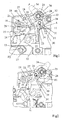
- a fixed contact piece 12 which cooperates with a movable contact piece 13 which is arranged on a contact lever 15 which is rotatably mounted on a bearing journal 14.
- the contact lever 15 is a Doppelarmhebel with a first Mixhebelarm 16 and a second Mixhebelarm 17; on the latter, the movable contact piece 13 is formed.
- a coupling element 18 is hinged, which has a U-shape with two projecting into the plane of legs 19 and 20.
- the leg 19 engages in a bore 21 on the contact lever, whereas the other leg 20 in a slot 22 in a tab 23 engages the other end via a journal 24 with a switching handle 25 which protrudes from a recess 26 in the front front wall 27.
- the switch knob 25 is rotatably mounted about a stationary axis 28 in the housing 10.
- the tab 23 has a projection 29 which covers the leg 19, so that the leg 19, the tab in the on state leads.
- a tab head 30 having a triangular peripheral contour, wherein the peripheral contour is provided with a circular arc-shaped cam surface 31, the circle center coincides with the center of the rotation axis 24.
- the middle bisector of the head 30 extends transversely to the longitudinal extent of the axis 23, the wider portion of the head being directed into the inside of the switch; the narrower, a kind of tip 32 forming area points to the front front side 27.
- a spring 33 is arranged, which acts as a torsion spring between the switch knob 25 and the tab 23 and to which a resilient arm 24 connects, which cooperates with the head 30 as follows: In the off position, as shown in FIG. 1, the leg or arm extends approximately in the direction of the longitudinal extent of the switching handle 34 of the switch knob 25 and approximately in the longitudinal direction of the mid-bisecting or symmetry line of the head 30.
- the arm 34 is outside the cam surface 31st and pushes with a force F 1 against the head 30 and thus against the tab 23, wherein the force vector of the force F 1 perpendicular to the arm 34 at a distance A at the axis of rotation 24 passes, so that over the distance A, referred to as the lever arm can be, the force exerts a torque on the tab 23, which seeks to pivot the tab about the axis 24 in a clockwise direction.
- a force F 2 is exerted on the leg 19 in the off state.
- a compression spring 40 is arranged, which serves as a contact pressure spring.
- the toggle lever joint is shown in the first stable position, during the turn-off the toggle mechanism is moved via a dead center in a second stable position, from which it by the spring forces of the arm 34 back into the Position is spent as shown in FIG. 2, in which the switch-on movement of the control handle is transmitted via the toggle mechanism on the contact lever.
- the axis of rotation 24 is located on a line which is perpendicular to the front wall 27 to the not-drawn fastening plane.
- the force F 1 extends, as indicated, outside the range between the axis of rotation 28 and the axis of rotation 24th
- the switching handle 34 When the switch is to spend in closed position, the switching handle 34 is pivoted clockwise about its axis of rotation 28 so that it is in the position shown in FIG. 2 passes. As a result, the connection point or the axis of rotation or articulation axis 24 moves according to the pivoting of the control handle 34 on a circular path about the axis 28 in the direction of the front front wall.
- the arm 34 slides relative to the front front wall 27- under the cam surface 31, so that the force F 1 ', which is perpendicular to the arm 31, in the area of the cam surface 31 presses on the head 30, wherein the arrangement is made in that the force curve F 1 is now aligned in the direction of the front front wall.
- the contact pressure spring 40 does not act on the knee joint, since the pivotable contact lever rests against a housing stop 41.
- the one leg 20 of the bracket 19 is free of force in the slot 22 of the tab 23 and has game.
- the spring or the spring arm 34 the position of the bracket 18 relative to the tab 23 is not exactly determined.
- the knee joint between the bracket 18 and the tab 23 could snap down, so that forms an obtuse angle between the bracket 18 and the tab 23, which is open to the front front wall.
- the knee angle would be negative and it would come to snapping at power.
- the spring arm 34 causes now due to the force of the spring force F 1 and the torque generated on the tab 23 is pressed about the hinge point 24 via the tab 23 always up to its maximum end position, whereby a power transmission is ensured in the longitudinal direction. It prevents the knee joint from snapping when switched on as well as when switching off. When switched on, the contact pressure spring 40 causes a stable knee joint and the force F 1 'of the arm 34 is not necessary and can thus pass through the pivot point 24 therethrough.
- the force F 1 is referred to as “first force” and the force F 1 'as “second force”.
- the force F 1 is perpendicular to the longitudinal extension of the control handle 34 and that in the direction of the movable contact piece, accordingly the end position of the switch knob 25 both in the position shown in FIG. 1 and in the position shown in FIG. 2, the arm 34 extends approximately in the longitudinal extent of the switching handle 34th
Landscapes
- Breakers (AREA)
Applications Claiming Priority (1)
| Application Number | Priority Date | Filing Date | Title |
|---|---|---|---|
| DE102005038149A DE102005038149A1 (de) | 2005-08-12 | 2005-08-12 | Leitungsschutzschalter |
Publications (1)
| Publication Number | Publication Date |
|---|---|
| EP1753005A1 true EP1753005A1 (fr) | 2007-02-14 |
Family
ID=37393860
Family Applications (1)
| Application Number | Title | Priority Date | Filing Date |
|---|---|---|---|
| EP06015648A Withdrawn EP1753005A1 (fr) | 2005-08-12 | 2006-07-27 | Disjoncteur-protecteur de ligne |
Country Status (5)
| Country | Link |
|---|---|
| US (1) | US7495189B2 (fr) |
| EP (1) | EP1753005A1 (fr) |
| CN (1) | CN1913074B (fr) |
| CA (1) | CA2555927A1 (fr) |
| DE (1) | DE102005038149A1 (fr) |
Cited By (1)
| Publication number | Priority date | Publication date | Assignee | Title |
|---|---|---|---|---|
| CN106449314A (zh) * | 2016-09-20 | 2017-02-22 | 加西亚电子电器股份有限公司 | 一种漏电断路器 |
Families Citing this family (12)
| Publication number | Priority date | Publication date | Assignee | Title |
|---|---|---|---|---|
| TWD117319S1 (zh) * | 2005-12-21 | 2007-06-01 | 星電股份有限公司 | 電路斷路器 |
| AU312378S (en) * | 2006-06-03 | 2007-01-15 | Chint Group Corp | Miniature circuit breaker |
| CA137493S (en) * | 2010-08-31 | 2011-06-03 | Abb Stotz Kontakt Gmbh | Electrical switch |
| CN103299385B (zh) * | 2011-01-05 | 2016-08-10 | 嘉灵科技有限公司 | 超薄型翘板设计 |
| CN202816829U (zh) * | 2012-09-20 | 2013-03-20 | 上海诺雅克电气有限公司 | 一种高稳定性小型断路器 |
| WO2015099771A1 (fr) * | 2013-12-27 | 2015-07-02 | Schneider Electric USA, Inc. | Poignée en deux pièces pour coupe-circuits miniatures |
| CN105702537B (zh) * | 2016-04-14 | 2017-12-01 | 乐清市智顺电气有限公司 | 电气保护装置 |
| DE102016108292A1 (de) * | 2016-05-04 | 2017-11-09 | Abb Schweiz Ag | Elektrisches Installationsgerät mit Schaltstellungsanzeige |
| US10984974B2 (en) * | 2018-12-20 | 2021-04-20 | Schneider Electric USA, Inc. | Line side power, double break, switch neutral electronic circuit breaker |
| CN109686626B (zh) * | 2018-12-28 | 2024-05-07 | 浙江正泰电器股份有限公司 | 小型断路器 |
| CN109727826B (zh) * | 2018-12-28 | 2024-08-13 | 浙江正泰电器股份有限公司 | 小型断路器 |
| US10510506B1 (en) * | 2019-01-31 | 2019-12-17 | Carling Technologies, Inc. | Narrow profile circuit breaker with arc interruption |
Citations (3)
| Publication number | Priority date | Publication date | Assignee | Title |
|---|---|---|---|---|
| DE3516217A1 (de) * | 1984-05-15 | 1985-11-21 | Mitsubishi Denki K.K., Tokio/Tokyo | Schaltungsunterbrecher |
| EP0255483A2 (fr) * | 1986-07-25 | 1988-02-03 | Weber Ag | Mécanisme de commutation d'un interrupteur de protection |
| DE19919420A1 (de) * | 1999-04-28 | 2000-11-02 | Siemens Ag | Schutzschalteinrichtung, beispielsweise Leitungsschutzschalter |
Family Cites Families (8)
| Publication number | Priority date | Publication date | Assignee | Title |
|---|---|---|---|---|
| DE1192730B (de) * | 1962-03-09 | 1965-05-13 | Licentia Gmbh | Schaltmechanismus fuer Selbstschalter |
| NL9102154A (nl) * | 1991-12-20 | 1993-07-16 | Holec Syst & Componenten | Elektrische schakelaar, in het bijzonder een last- of vermogensschakelaar. |
| EP0616347B1 (fr) * | 1993-03-17 | 1998-03-11 | Ellenberger & Poensgen GmbH | Disjoncteur multipolaire |
| US5753878A (en) * | 1996-04-23 | 1998-05-19 | General Electric Company | Circuit breaker having variable arc gas venting |
| DE10133878B4 (de) * | 2001-07-12 | 2004-07-08 | Siemens Ag | Schaltgerät mit einem Schaltschloss |
| US6897747B2 (en) * | 2002-05-10 | 2005-05-24 | Joseph T. Brandon | Circuit breaker |
| GB2421120B (en) * | 2003-09-23 | 2007-03-28 | Moeller Gebaeudeautomation Kg | Switch |
| ZA200506062B (en) * | 2004-10-04 | 2007-12-27 | Circuit Breaker Ind | Trip indicative rocker switch |
-
2005
- 2005-08-12 DE DE102005038149A patent/DE102005038149A1/de not_active Withdrawn
-
2006
- 2006-07-27 EP EP06015648A patent/EP1753005A1/fr not_active Withdrawn
- 2006-08-10 CA CA002555927A patent/CA2555927A1/fr not_active Abandoned
- 2006-08-11 US US11/502,522 patent/US7495189B2/en not_active Expired - Fee Related
- 2006-08-14 CN CN2006101149574A patent/CN1913074B/zh not_active Expired - Fee Related
Patent Citations (3)
| Publication number | Priority date | Publication date | Assignee | Title |
|---|---|---|---|---|
| DE3516217A1 (de) * | 1984-05-15 | 1985-11-21 | Mitsubishi Denki K.K., Tokio/Tokyo | Schaltungsunterbrecher |
| EP0255483A2 (fr) * | 1986-07-25 | 1988-02-03 | Weber Ag | Mécanisme de commutation d'un interrupteur de protection |
| DE19919420A1 (de) * | 1999-04-28 | 2000-11-02 | Siemens Ag | Schutzschalteinrichtung, beispielsweise Leitungsschutzschalter |
Cited By (1)
| Publication number | Priority date | Publication date | Assignee | Title |
|---|---|---|---|---|
| CN106449314A (zh) * | 2016-09-20 | 2017-02-22 | 加西亚电子电器股份有限公司 | 一种漏电断路器 |
Also Published As
| Publication number | Publication date |
|---|---|
| CN1913074B (zh) | 2010-12-22 |
| US20070034495A1 (en) | 2007-02-15 |
| DE102005038149A1 (de) | 2007-02-22 |
| CA2555927A1 (fr) | 2007-02-12 |
| US7495189B2 (en) | 2009-02-24 |
| CN1913074A (zh) | 2007-02-14 |
Similar Documents
| Publication | Publication Date | Title |
|---|---|---|
| DE10152425B4 (de) | Leitungsschutzschalter | |
| DE102007015190A1 (de) | Schutzschalter | |
| EP1753005A1 (fr) | Disjoncteur-protecteur de ligne | |
| WO2008052702A1 (fr) | Commutateur électrique | |
| DE3342469A1 (de) | Elektrischer schalter | |
| DE69636639T2 (de) | Lastschalter | |
| EP0184652A2 (fr) | Interrupteur avec coupe-circuit | |
| DE102004055564B4 (de) | Elektrisches Installationsschaltgerät | |
| DE2711167A1 (de) | Schaltgestaenge fuer einen elektrischen niederspannungs-schalter | |
| DE69014741T2 (de) | Betätigungsmechanismus für elektrischen Schalter. | |
| EP1728260B1 (fr) | Mecanisme de commutation pour appareil de distribution d'installation electrique | |
| DE3119165A1 (de) | Selbstschalter als baueinheit aus einem leitungsschutzschalter sowie hilfs- und signalschaltern | |
| DE3729688A1 (de) | Schaltungsunterbrecher | |
| EP0586733B1 (fr) | Dispositif à action brusque pour interrupteurs électriques | |
| EP0091040A2 (fr) | Disjoncteur de protection à courant excessif | |
| DE102007003403B4 (de) | Elektrischer Schalter | |
| EP0147629B1 (fr) | Disjoncteur de protection | |
| DE10218526B4 (de) | Schaltgerät | |
| EP1709660B1 (fr) | Interrupteur electromecanique | |
| DE29917173U1 (de) | Betätigungseinrichtung für ein elektrisches Überstromrelais | |
| DE19507605C1 (de) | Verklinkungseinrichtung für elektrische Schalter | |
| EP1555681A1 (fr) | Commutateur électrique | |
| EP1659604B1 (fr) | Appareil de commutation pour une installation électrique | |
| DE4339425A1 (de) | Schaltschloß für einen Fehlerstromschutzschalter | |
| EP1894218A1 (fr) | Appareil de commutation, disjoncteur de ligne et analogue |
Legal Events
| Date | Code | Title | Description |
|---|---|---|---|
| PUAI | Public reference made under article 153(3) epc to a published international application that has entered the european phase |
Free format text: ORIGINAL CODE: 0009012 |
|
| AK | Designated contracting states |
Kind code of ref document: A1 Designated state(s): AT BE BG CH CY CZ DE DK EE ES FI FR GB GR HU IE IS IT LI LT LU LV MC NL PL PT RO SE SI SK TR |
|
| AX | Request for extension of the european patent |
Extension state: AL BA HR MK YU |
|
| 17P | Request for examination filed |
Effective date: 20070404 |
|
| AKX | Designation fees paid |
Designated state(s): AT BE BG CH CY CZ DE DK EE ES FI FR GB GR HU IE IS IT LI LT LU LV MC NL PL PT RO SE SI SK TR |
|
| GRAP | Despatch of communication of intention to grant a patent |
Free format text: ORIGINAL CODE: EPIDOSNIGR1 |
|
| GRAS | Grant fee paid |
Free format text: ORIGINAL CODE: EPIDOSNIGR3 |
|
| RAP1 | Party data changed (applicant data changed or rights of an application transferred) |
Owner name: ABB AG |
|
| STAA | Information on the status of an ep patent application or granted ep patent |
Free format text: STATUS: THE APPLICATION IS DEEMED TO BE WITHDRAWN |
|
| 18D | Application deemed to be withdrawn |
Effective date: 20110201 |