EP1753320B1 - Gitterstuhlbestandteil - Google Patents
Gitterstuhlbestandteil Download PDFInfo
- Publication number
- EP1753320B1 EP1753320B1 EP05747961A EP05747961A EP1753320B1 EP 1753320 B1 EP1753320 B1 EP 1753320B1 EP 05747961 A EP05747961 A EP 05747961A EP 05747961 A EP05747961 A EP 05747961A EP 1753320 B1 EP1753320 B1 EP 1753320B1
- Authority
- EP
- European Patent Office
- Prior art keywords
- chair
- component
- panels
- membranous
- frame
- Prior art date
- Legal status (The legal status is an assumption and is not a legal conclusion. Google has not performed a legal analysis and makes no representation as to the accuracy of the status listed.)
- Expired - Lifetime
Links
Images




Classifications
-
- A—HUMAN NECESSITIES
- A47—FURNITURE; DOMESTIC ARTICLES OR APPLIANCES; COFFEE MILLS; SPICE MILLS; SUCTION CLEANERS IN GENERAL
- A47C—CHAIRS; SOFAS; BEDS
- A47C7/00—Parts, details, or accessories of chairs or stools
- A47C7/02—Seat parts
- A47C7/28—Seat parts with tensioned springs, e.g. of flat type
- A47C7/282—Seat parts with tensioned springs, e.g. of flat type with mesh-like supports, e.g. elastomeric membranes
Definitions
- the present invention relates to chairs that include a mesh support surface, and more particularly, to the back rest, armrest, head rest, or seat of such a chair.
- US 3,709,557 discloses a column support for use in chairs.
- the support comprises two elongated sheets of flexible material forming an envelope with a pair of spaced apart pockets arranged either side of the user's vertebral column. Each of the pockets containing rigidifying means.
- WO 01/93907 discloses a chair comprising a lower back support and an upper back support which are molded from a plastic.
- a chair having a mesh support surface where the mesh has a contour that adapts to the user's body It would be further advantageous to provide such a chair in coordination with a contoured frame for the relevant portion of the chair.
- GB-A-1 428 185 discloses a decorative panel primarily used as a seat base for chairs and which simulates woven straw upholstery.
- Four triangles, each of which extends into a flap, is cut from a sheet of decorative covering material. These four triangles are sewn together, edge to edge, so as to simulate the seat of a chair.
- the resultant assembly is then placed over a frame, with a cushion of semi-hard foam interposed between the frame and an underlying base board of perforated plywood.
- the flaps of the triangles are then folded back under the bottom of the board and secured.
- the resultant chair seat is said not to tend to sag, in contrast to seats of straw-upholstered chair seat bases.
- a contoured membranous chair component comprising:
- the component is beneficially contoured to support a user and is capable of displacement for accommodation of various body shapes.
- the chair component may form the seat, arm rest, head rest or back rest of a chair and typically comprises three or more panels. It is preferred that the chair component has no more than ten panels.
- each panel is cut, or otherwise formed, in a shape so that when the several panels are combined, together they form a chair component, such as a seat, back rest, or headrest that is capable of beneficially adapting to the user's shape.
- the panels are capable of being combined in a conventional fashion.
- the panels can be combined by sewing the panels together, by welding them together (such as by sonic welding), or by using an adhesive to bind the panels together.
- the chair component surface of the present invention has at least two straight or curvilinear seams. In a preferred embodiment, the seams are curvilinear. It is preferred that the chair component surface of the present invention has fewer than ten seams between panels.
- a back rest made according to the present invention provides a mesh back rest having lumbar support without the necessity of an additional solid structure.
- a mesh back rest according to the present invention can have contours without a pad applying pressure to the mesh to achieve beneficial contours.
- panel contour refers to a three dimensional shape of a chair component that results from the combination of a plurality of membranous panels.
- the "panel contour” differs from the three dimensional shape produced by a contoured frame.
- the chair component comprises a single mesh panel covering a contoured component frame.
- the chair component is particularly useful as a chair seat.
- the seat is thus particularly adapted to be substantially contoured to the various users' body shapes and distribute pressure of the user's lower body.
- the chair component comprises a head rest.
- the head rest comprises at least one mesh panel that is contoured to substantially conform to the shape of the user's head.
- the head rest comprises one or more panels.
- a chair component such as a seat, arm rest, back rest or head rest, is formed from a plurality of panels from a membranous material using a contoured component frame.
- mesh chair components are combined with other parts to form a chair.
- a mesh seat according to the invention could be combined with a back rest and a plurality of legs to form a chair.
- one or more components of the chair can be a mesh component according to the invention.
- a chair comprising a chair pedestal, a base mounted on the pedestal, a seat mounted on the base, and a back rest attached to the base.
- the pedestal contains a height adjustment mechanism such as a gas spring.
- the back rest could be pivotally connected to the base.
- the back rest is pivotally connected to the base at a point roughly corresponding to the lumbar region of a user's back. Obviously, such a base would require an upward extension so at to form the pivot connection in that area.
- the back rest comprises at least three membranous panels.
- the seat can also comprise one or more membranous panels.
- the present invention also encompasses further embodiments wherein there is provided a chair having at least one component comprising a contoured mesh panel.
- the chair is a swivel chair comprising a base pivotally supporting a seat, optionally including a back, arms, and a head rest, wherein at least one of said seat, back, arms, and headrest is comprised of at least one contoured mesh panel.
- the chair comprises four legs stationarily attached to a seat, optionally including a back and arms, wherein at least one of the seat, back, and arms comprise at least one contoured mesh panel.
- the present invention provides chair components, and chair made using the components, wherein the chair components include a mesh portion.
- the mesh chair components such as chair seats, back rests, head rests, and chair arms, are particularly advantageous in that the mesh is beneficially contoured to provide ergonomic support to the user.
- the mesh chair components are particularly designed to be adaptable to the various body shapes of multiple users while still providing ergonomic support.
- the mesh chair components of the invention are particularly useful in that they can be incorporated into a number of various embodiments.
- one or more of the mesh components of the invention can be incorporated into an office chair (such as including casters), a standard four-leg chair, household seating, public seating facilities (such as stadium seating, movie theatre seating, arena seating, and the like), public transportation seating (such as airplane seating, train seating, bus seating, and the like), professional service seating (such as a dental exam chair), and other similar or related seating apparatuses.
- the mesh chair components of the invention can also be incorporated into other types of vehicle seating, such as automobile seating. Accordingly, the present invention also encompasses all of the various seating embodiments described above incorporating at least one mesh component as described herein.
- Figure 1 shows a chair back rest 100 according to one embodiment of the present invention.
- the periphery of the chair back rest 100 is a component frame 110, which includes an aperture 115.
- the aperture 115 is capable of receiving a pin, thereby allowing connection the chair back rest 100 to additional chair components, such as to an arm extending from a chair base (not shown).
- the mesh back rest is made from three mesh panels, namely right panel 120, center panel 130, and left panel 140.
- Right panel 120 and left panel 140 are substantially mirror images of one another; however, in further embodiments of the invention, this is not necessarily required.
- Center panel 130 has a shape that is substantially different from that of either right panel 120 or left panel 140.
- center panel 130 is encouraged into an appropriate vertical contour by tension exerted by right panel 120 and left panel 140, to which center panel 130 is joined.
- the various panels, 120, 130, and 140 can be adapted to form beneficial contours for receiving various users' body shapes.
- the width of right panel 120 and left panel 140, in proportion to center panel 130 is such that the tension on the panels from the force provided by the component frame 110 lifts center panel 130 to the correct contour.
- areas of the back rest 100 where it is beneficial to have contours that are less pronounced such as, for example, in the area of the back rest 100 adaptable for receiving the shoulder area of a user, less tensile force is required.
- right panel 120 and left panel 140 are narrower and center panel 130 is wider. This effect is illustrated in Figure 1 , where center panel 130 is narrower in the lower area of the back rest 100 adaptable to the lumbar area of a user, and becomes wider in the upper area of the back rest 100 adaptable to the shoulder area of a user.
- a mesh chair component such as a back rest
- beneficial contours in desirable areas of the component Accordingly, the invention allows for preparation of specialized components that are beneficially contoured for special needs users. Additionally, the chair components can be made to have contours in positions, such as generally in the lumbar region, that are beneficial for a wide range of users.
- the panels used to make the chair components of the invention can be made from any conventional membranous fabric.
- the panels are especially useful as a mesh fabric, such as nylon, polyester, or other synthetic or natural fibers or skins.
- the panels can be made from leather that has been selectively perforated to substantially emulate a mesh-type material.
- the perforations could be patterned or unpatterned to impart additional desirable qualities to the panels.
- the mesh fabric could be comprised of a blend of materials, such as a polyester/nylon blend.
- each of the panels is made from the same type of fabric.
- each of the panels is made from a polyester weave mesh.
- the material used in preparing the mesh component according to the present invention have a limited stretch ability. Accordingly, the material should have a stretch ability of less than about 10%, preferably less than about 8%, more preferably less than about 6%. It is generally preferred for the material to have a stretch ability on the order of about 5%. Such limited stretch allows for the most effective use of the contours generated according to the invention. The limited stretch allows for maintenance of the support generated by the contours while still providing the comfort of the mesh.
- One method of measuring the stretch ability of a membranous material is to take an about two by about twelve inch piece of the membranous material and hang the material vertically. An about twenty pound weight is attached to the bottom of the membranous material. After the weight/material combination has come to equilibrium (for example, after about a half hour), the length of the "stretched” material is measured and compared to the length of the material before the weight was applied.
- a material is of limited stretch ability if the ratio of the length of the "stretched" material to the initial length is less than about 1.10, preferably less than about 1.08, more preferably less than about 1.06.
- a material of limited stretch ability particularly useful according to the invention has a ratio of around 1.05.
- the membranous material not be pulled too tightly within the outer component frame.
- pre-stretching of the material is not required since the limited stretch ability of the material in connection with the contouring of the panels provides sufficient tension without the need for pre-stretching.
- the vertical radius at the lumbar area should be within the range of about 9 inches to about 15 inches. Additionally, the horizontal radius at the lumbar area should be within the range of about 13 inches to about 16 inches and should be within the range of about 22 inches to about 26 inches at the shoulder area of the back rest.
- limited stretch material is advantageous over the use of material having a greater stretch ability as it allows for displacement of the material, rather than stretching, which is more accommodative.
- Mesh material with a stretch ability that is not limited allows the material to conform to the position of the user, which facilitates, or even promotes, poor posture and ergonomically unsound seating.
- limited stretch material undesirable positions of the body are not possible as they would be with material having a greater stretch ability.
- Use of a material having limited stretch ability with modest tension across the component frame, as described above, allows for displacement of the material that accommodates the differing body shapes of various users while maintaining beneficial support.
- a lumbar contour in a mesh back rest can adjust to the individual back shape and size of various users because the contour can be displaced to correspond to the area of the natural lumbar contour of the user, but the supportive contour of the mesh is maintained, thereby providing support, rather than just stretching without providing needed support.
- right panel 120 is joined to center panel 130 by right seam 125 and center panel 130 is joined to left panel 140 by left seam 135.
- Seams 125 and 135 can be made by any conventional method of joining the mesh fabric including, but not limited to, sewing, welding, and gluing. In one particular embodiment, the seams are joined by ultrasonic welding.
- the membranous material can be attached to the component frame by any conventional method.
- One preferred method is by attaching the material, such as by welding or gluing, to a flexible strip, such as a spline, and fitting the combination into a grove formed in the component frame.
- the membranous material is sewn to a spline.
- the combination is generally fitted into the groove at a right angle to the direction of the tension on the material.
- the flexible strip used in attaching the material to the component frame can be made from any material commonly known for such uses, and is desirably a plastic-type extrusion, such as polyethylene or an equivalent.
- Figure 2 shows another view of the mesh component back rest according to the embodiment shown in Figure 1 .
- component frame 110 about the periphery of the back rest 100 is component frame 110, and within the component frame are right panel 120, center panel 130, and left panel 140.
- right panel 120 is joined to center panel 130 by right seam 125
- center panel 130 is joined to left panel 140 by left seam 135.
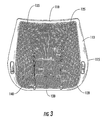
- Figure 3 shows back rest 100 of Figure 2 from the obverse view.
- Figure 3 provides a more detailed view of the component frame 110 according to one embodiment of the invention.
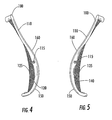
- Figures 4 and 5 show one embodiment of the back rest 100 from the right and left sides. From these views, it can be seen that in this particular embodiment of the present invention, the component frame 110 has a curvature that provides additional contour to the back rest 100 so as to provide further support for the user.
- the curvature shown in these figures can be referred to as a side view curvature. As seen in each of these figures, this side view curvature begins at the bottom of the component frame. From the bottom, the frame goes, or curves, forward (shown as curvature 150). Subsequently, for example from about the lumbar region (which is about a quarter of the way up the chair back), the side view curvature inverts and heads backward (shown as curvature 160).
- Figures 6 and 7 provide top perspective views of the back rest 100 from the front and back. From these views, it can be seen that in this particular embodiment of the present invention, the component frame 110 has a top view curvature that provides further contour to the back rest 100 so as to provide additional support for the user. For instance, both the top and the bottom edges of the component frame 110 have a concave shape (170, and 180, respectively). The concave shape 180 of the bottom edge of the component frame 110 is not visible in Figure 6 due to the forward curvature of the component frame 110 discussed above.
- chairs could be made, according to the invention, having mesh components comprising further chair parts, such as, for example, a chair seat, a chair arm, or a head rest.
- Figure 8 provides a front perspective view of a chair seat 200 according to one embodiment of the present invention.
- the periphery of the chair seat 200 is a component frame 210, which encompasses only three sides of the chair seat 200, thus having a substantially U-shaped conformation.
- the front edge 230 of the chair seat 200 is devoid of framing in order to avoid a hardened area whereby pressure could be applied to the user's body. In this manner, a more comfortable seating arrangement is provided since the comfort of the mesh component extends through the front portion of the chair seat 200 without the need of an additional structural component that could act as a pressure point on the body of the user.
- the chair seat 200 is comprised of a single membranous panel 220.
- Figure 9 provides a side view of the chair seat 200.
- the component frame 210 maybe contoured (i.e. have a side view curvature) to improve the effect of the membranous panel 220 to distribute pressure of the user's lower body.
- the chair seat 200 preferably has an upward curvature 240 toward the front portion of seat 200 and preferably has a downward curvature 250 toward the middle and back of seat 200.
- Such curvatures can be advantageously designed to receive the lower body of a user in an ergonomically correct sitting position, evenly and comfortably distributing the pressure of the user's lower body.
- the curvatures of the chair seat 200 are designed for encouraging an ergonomically correct upright posture by the user.
- the panel 220 is stretched side-to-side across component frame 210 with a tension that, preferentially, is greater than the tension applied to the panels of a back rest according to the present invention.
- a greater tension is preferred in the chair seat embodiment over the back rest embodiment as the chair seat must support the weight of the user.
- the chair seat generally relies on the particular contouring of the component frame, while in the back rest embodiment, support is also provided by the contours formed by the multi-panel construction.
- the front edge 230 of the chair seat 200 have a "waterfall” effect.
- This effect can be achieved by appropriate contouring of the front edges of the side portions of component frame 210.
- a chair according to the present invention can include a mesh seat according to the above embodiment.
- a chair according to the present invention can include a seat comprising a standard cushion and upholstery. Either seat embodiment could be included in a chair comprising a back rest comprising contoured mesh panels as described herein.
- Figure 10 provides a front perspective view of a head rest 300 according to the present invention.
- the periphery of the head rest 300 is a component frame 310.
- the component frame 310 is contoured to improve the effect of the panel 320 in receiving the head of the user.
- the component frame 310 has a forward curvature 350 along the horizontal axis.
- the head rest as shown in the embodiment of Figure 10 , can have a single mesh panel 320 attached to component frame 310. Alternately, the head rest can have a plurality of panels, such as in the back rest embodiment described above.
- the panels are attached such that when they are combined, they are contoured for substantially conforming to the head of a user.
- a head rest according to this embodiment may be contoured such that it provides support at the base of the head of the user in the neck region while also receiving the more rounded back portion of the user's head.
- the component frame of the head rest component can also have a curvature varied from the embodiment of Figure 10 but beneficial for receiving the contoured, multi-panel mesh.
- the head rest of the present invention is further illustrated in Figure 11 , which provides a front view of the head rest. Accordingly, this view illustrates a single mesh panel 320 stretched across the component frame 310.
- a side view of the head rest 300 along lines A-A is provided in Figure 11A , which further illustrates the forward curvature 350 of the component frame 310 in this embodiment of the invention.
- the head rest 300 further comprises apertures 315 and 317 for receiving pins for attachment to supports (not shown).
- a top view of the head rest 300 along lines B-B of Figure 11 is provided in Figure 11B , which illustrates optional additional backward curvature 360 along the vertical axis. The additional curvature allows for maximizing the contouring ability of the head rest for receiving the head of a user and providing beneficial support.
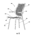
- Figure 12 illustrates a chair 400 having a front support piece 410 and two rear support pieces 420 and 422.
- the front support 410 is a single shaped piece acting as two front leg pieces and as a frame support for attachment of the seat frame 430.
- the front support 410 could comprise two separate members as front leg pieces.
- the seat frame 430 is substantially U-shaped having no support member along the front edge of the seat frame 430, which is beneficially contoured for supporting a user's body and covered by mesh 440.
- the rear support pieces 420 and 422 function as two rear leg pieces and are preferentially attached to the front support piece 410 for added stability.
- the rear support pieces 420 and 422 are further adapted for use as arm supports 450 and 452.
- the rear support pieces 420 and 422 are also useful as supports for the back rest 460.
- the back rest 460 is preferentially designed to be interchangeable between different chair embodiments.
- the back rest 460 is preferentially made according to the embodiments previously described according to the present invention.
- the back rest 460 comprises only a single mesh piece and is not it accordance with the present invention. When the back rest 460 comprises multiple mesh pieces as described above it become it accordance with the present invention.
- chair 400 could be made without the arms 450 and 452.
- rear support pieces 420 and 422 would preferentially terminate at some point along seat back 460.
- the back rest could be a mesh component according to the present invention and the chair seat could be a conventional seat, such as a hard surface covered by foam or other padded cushioning.
- a chair according to the invention could comprise a pedestal, such as one having a plurality of outwardly extending support arms. Such support arms could further comprise components for facilitating movement of the chair, such as casters.
- the pedestal includes a height adjustment mechanism.
- the height adjustment mechanism is a gas spring.
- the pedestal could further comprise a base attached thereto capable of supporting and having attached thereto additional chair components.
- a back rest according to the present invention could be pivotally connected to the base, such as through a pivot connecting member extending upward from the base.
- the back rest is pivotally connected to the base at a point roughly corresponding to the lumbar region of a user's back.
- the base could support a chair seat.
- the chair seat is a mesh chair seat according to the present invention.
- the chair seat is a conventional chair seat.
- the present invention also encompasses further embodiments wherein there is provided a chair having at least one component comprising a contoured mesh panel.
- the chair is a swivel chair comprising a base pivotally supporting a seat.
- the chair can optionally include a back rest, arms, and a head rest, wherein at least one of the chair seat, back rest, arms, and headrest is comprised of at least one contoured mesh panel.
Landscapes
- Chair Legs, Seat Parts, And Backrests (AREA)
- Special Chairs (AREA)
- Acyclic And Carbocyclic Compounds In Medicinal Compositions (AREA)
- Chairs For Special Purposes, Such As Reclining Chairs (AREA)
Claims (51)
- Konturierter membranartiger Stuhlbestandteil, umfassend:einen gebogenen Bauteilrahmen (110) mit einem Befestigungsmechanismus zum Befestigen des Bauteilrahmens (110) an einem Stuhl undwenigstens zwei membranartige Paneele (120, 130, 140), die durch wenigstens eine Naht verbunden sind, um ein größeres membranartiges Paneel zu bilden, das über den gebogenen Bauteilrahmen gespannt und an diesem so befestigt ist, dass aufgrund der von dem gebogenen Bauteilrahmen ausgeübten Kraft auftretende Spannung in den wenigstens zwei membranartigen Paneelen dazu führt, dass das sich ergebende größere Paneel eine Krümmung in seitlicher Richtung sowie von oben nach unten aufweist.
- Stuhlbestandteil nach Anspruch 1, dadurch gekennzeichnet, dass der Bestandteil eine Rükkenlehne (100) beinhaltet.
- Stuhlbestandteil nach Anspruch 2, dadurch gekennzeichnet, dass die Kontur des Paneels in der Rückenlehne eine Lordosenstütze bereitstellt.
- Stuhlbestandteil nach einem der Ansprüche 2 oder 3, dadurch gekennzeichnet, dass der Rahmen (110) von der Seite gesehen eine Krümmung aufweist, die am unteren Ende des Rahmens (110) nach vorne und in der Nähe des oberen Endes des Rahmens (110) nach hinten verläuft.
- Stuhlbestandteil nach Anspruch 1, dadurch gekennzeichnet, dass der Bestandteil einen Sitz (200) beinhaltet.
- Stuhlbestandteil nach Anspruch 5, dadurch gekennzeichnet, dass der Bauteilrahmen des Sitzes U-förmig ist.
- Stuhlbestandteil nach einem der Ansprüche 5 oder 6, dadurch gekennzeichnet, dass der Sitz im vorderen Bereich des Sitzes von der Seite gesehen eine Krümmung in Form eines Wasserfalls aufweist.
- Stuhlbestandteil nach einem der vorhergehenden Ansprüche, dadurch gekennzeichnet, dass wenigstens eines der Paneele eine nicht-rechteckige Form aufweist.
- Stuhlbestandteil nach einem der Ansprüche 1 bis 7, dadurch gekennzeichnet, dass wenigstens eines der Paneele eine Form aufweist, die kein Parallelogramm ist.
- Stuhlbestandteil nach einem der vorhergehenden Ansprüche, dadurch gekennzeichnet, dass die wenigstens eine Naht wenigstens eine gekrümmte Naht umfasst.
- Stuhlbestandteil nach einem der vorhergehenden Ansprüche, dadurch gekennzeichnet, dass die wenigstens zwei membranartigen Paneele aus synthetischem oder natürlichem Material bestehen.
- Stuhlbestandteil nach einem der Ansprüche 1 bis 10, dadurch gekennzeichnet, dass die wenigstens zwei membranartigen Paneele ein gewebtes Netz aus Polyester umfassen
- Stuhlbestandteil nach einem der vorhergehenden Ansprüche, dadurch gekennzeichnet, dass wenigstens eines der wenigstens zwei membranartigen Paneele eine begrenzte Dehnbarkeit aufweist.
- Stuhlbestandteil nach Anspruch 13, dadurch gekennzeichnet, dass die Dehnbarkeit kleiner oder gleich ungefähr 5% ist.
- Stuhlbestandteil nach einem der vorhergehenden Ansprüche, dadurch gekennzeichnet, dass der Bestandteil drei oder mehr membranartige Paneele (120, 130, 140) umfasst.
- Stuhlbestandteil nach einem der vorhergehenden Ansprüche, dadurch gekennzeichnet, dass die Paneele (120, 130, 140) miteinander durch ein Verfahren verbunden sind, das aus der Gruppe ausgewählt ist, welche aus Nähen, Schweißen und Kleben besteht.
- Stuhlbestandteil nach Anspruch 16, dadurch gekennzeichnet, dass die Paneele (120, 130, 140) durch Schallschweißen miteinander verbunden sind.
- Stuhlbestandteil nach einem der vorhergehenden Ansprüche, dadurch gekennzeichnet, dass der Rahmen (110) weiter eine Rille zum Aufnehmen der wenigstens zwei membranartigen Paneele umfasst.
- Stuhlbestandteil nach Anspruch 18, dadurch gekennzeichnet, dass die wenigstens zwei membranartigen Paneele an dem Rahmen (110) mittels eines flexiblen Extrudats aus Kunststoff befestigt werden, das an den wenigstens zwei membranartigen Paneelen angebracht und in die Rille gezwängt wird.
- Stuhlbestandteil nach Anspruch 19, dadurch gekennzeichnet, dass die wenigstens zwei membranartigen Paneele an das Extrudat aus Kunststoff angenäht sind.
- Stuhlbestandteil nach Anspruch 1, dadurch gekennzeichnet, dass der Bestandteil eine Kopfstütze (300) umfasst.
- Stuhlbestandteil nach Anspruch 21, dadurch gekennzeichnet, dass die Kopfstütze entlang einer horizontalen Achse nach vorne gekrümmt ist.
- Stuhlbestandteil nach einem der Ansprüche 21 oder 22, dadurch gekennzeichnet, dass die Kopfstütze (300) entlang einer vertikalen Achse nach hinten gekrümmt ist.
- Stuhlbestandteil nach einem der Ansprüche 2 bis 4, dadurch gekennzeichnet, dass die Rükkenlehne umfasst:zwischen drei und zehn Textilpaneele, von denen wenigstens zwei eine membranartige Textilstruktur beinhalten und wobei wenigstens eines der Paneele eine nicht-rechteckige Form aufweist, undwenigstens zwei gekrümmte Nähte
- Stuhl, dadurch gekennzeichnet, dass er den Stuhlbestandteil nach einem der vorhergehenden Ansprüche umfasst.
- Stuhl, der den Stuhlbestandteil nach Anspruch 1 und weiter Folgendes umfasst:einen Stuhlsockelein Grundelement, das auf dem Sockel montiert ist, undeinen Sitz, der auf dem Grundelement montiert ist,dadurch gekennzeichnet, dass der Stuhlbestandteil eine Rückenlehne (100) umfasst und an dem Grundelement befestigt ist.
- Stuhl, der den Stuhlbestandteil nach Anspruch 1 und weiter Folgendes umfasst:ein vorderes Stützbauteil (410)zwei hintere Stützbauteile (420, 422) undeinen Sitz (200), der an dem vorderen Stützbauteil (410) befestigt ist,dadurch gekennzeichnet, dass der Stuhlbestandteil eine Rückenlehne (100) ist und an den hinteren Stützbauteilen (420, 422) befestigt ist.
- Stuhl nach einem der Ansprüche 26 oder 27, dadurch gekennzeichnet, dass die wenigstens eine Naht (125, 135) gekrümmt ist.
- Stuhl nach einem der Ansprüche 26 bis 28, dadurch gekennzeichnet, dass wenigstens eines der membranartigen Paneele eine nicht-rechteckige Form aufweist.
- Stuhl nach einem der Ansprüche 26 bis 29, dadurch gekennzeichnet, dass die Paneelkontur eine Abstützung des Lendenbereichs eines Nutzers bewirkt.
- Stuhl nach einem der Ansprüche 26 bis 30, dadurch gekennzeichnet, dass die Rückenlehne (100) weiter einen Bauteilrahmen (110) umfasst, der wenigstens drei der membranartigen Paneele (120, 130, 140) festhält.
- Stuhl nach Anspruch 31. dadurch gekennzeichnet, dass der Bauteilrahmen (110) in seitlicher Richtung sowie von oben nach unten eine gekrümmte Form aufweist.
- Stuhl nach einem der Ansprüche 31 oder 32, dadurch gekennzeichnet, dass der Bauteilrahmen (110) von der Seite gesehen eine Krümmung aufweist, die am unteren Ende des Rahmens (110) nach vorne und in der Nähe des oberen Endes des Rahmens (110) nach hinten verläuft.
- Stuhl nach einem der Ansprüche 26 bis 33, dadurch gekennzeichnet, dass wenigstens eines der membranartigen Paneele (120, 130, 140) eine Dehnbarkeit von weniger als ungefähr 6% aufweist.
- Stuhl nach Anspruch 26, dadurch gekennzeichnet, dass der Stuhlsockel eine Mehrzahl von sich nach außen erstreckenden Armen mit Laufrollen umfasst.
- Stuhl nach einem der Ansprüche 26 oder 35, dadurch gekennzeichnet, dass er weiter eine in dem Sockel montierte Gasdruckfeder umfasst.
- Stuhl nach einem der Ansprüche 26 bis 36, dadurch gekennzeichnet, dass er weiter eine Kopfstütze (300) umfasst.
- Stuhl nach Anspruch 37, dadurch gekennzeichnet, dass die Kopfstütze ein oder mehrere membranartige Paneele (320) umfasst.
- Stuhl nach Anspruch 26, dadurch gekennzeichnet, dass der Sockel einen drehbaren Sockel umfasst.
- Stuhl nach einem der Ansprüche 26 bis 39, dadurch gekennzeichnet, dass er weiterhin Arme umfasst.
- Stuhl nach Anspruch 40, dadurch gekennzeichnet, dass die Arme an der Rückenlehne befestigt sind.
- Stuhl nach Anspruch 40, dadurch gekennzeichnet, dass die Arme unabhängig voneinander einstellbar sind.
- Stuhl nach einem der Ansprüche 26 bis 42, dadurch gekennzeichnet, dass der Sitz (200) ein oder mehrere membranartige Paneele umfasst.
- Stuhl nach einem der Ansprüche 26 bis 43, dadurch gekennzeichnet, dass der Sitz (200) einen U-förmigen Bauteilrahmen (210) umfasst, der einen vorderen Bereich in Form eines Wasserfalls hat.
- Stuhl nach Anspruch 27, dadurch gekennzeichnet, dass das vordere Stützbauteil (410) zwei Beine umfasst.
- Stuhl nach einem der Ansprüche 27 oder 45, dadurch gekennzeichnet, dass die hinteren Stützbauteile (420, 422) an dem vorderen Stützbauteil (410) befestigt sind.
- Stuhl nach einem der Ansprüche 27, 45 oder 46, dadurch gekennzeichnet, dass die hinteren Stützbauteile (420, 422) weiter Armlehnen (450, 452) umfassen.
- Verfahren zum Herstellen des membranartigen Stuhls nach Anspruch 1, umfassend:das Bereitstellen des Bauteilrahmens, wobei der Bauteilrahmen eine Rille zum Aufnehmen eines Profils aufweist,das Bereitstellen der wenigstens zwei membranartigen Paneeledas Befestigen einer Umfangskante der wenigstens zwei membranartigen Paneele an dem Profil unddas Einfügen des Profils in die Rille.
- Verfahren nach Anspruch 48, dadurch gekennzeichnet, dass es das Bereitstellen von wenigstens drei membranartigen Paneelen umfasst.
- Verfahren nach Anspruch 49, dadurch gekennzeichnet, dass es weiter das Verbinden der wenigstens drei membranartigen Paneele durch wenigstens zwei gekrümmte Nähte umfasst.
- Verfahren nach Anspruch 50, dadurch gekennzeichnet, dass es das Verbinden der wenigstens drei membranartigen Paneele miteinander durch Schallschweißen umfasst.
Priority Applications (1)
| Application Number | Priority Date | Filing Date | Title |
|---|---|---|---|
| EP09007121A EP2108286B1 (de) | 2004-05-13 | 2005-05-13 | Stuhl mit säulenförmigem Fuss mit Membranplatten |
Applications Claiming Priority (2)
| Application Number | Priority Date | Filing Date | Title |
|---|---|---|---|
| US57061104P | 2004-05-13 | 2004-05-13 | |
| PCT/US2005/016550 WO2005112704A2 (en) | 2004-05-13 | 2005-05-13 | Mesh chair component |
Related Child Applications (1)
| Application Number | Title | Priority Date | Filing Date |
|---|---|---|---|
| EP09007121A Division EP2108286B1 (de) | 2004-05-13 | 2005-05-13 | Stuhl mit säulenförmigem Fuss mit Membranplatten |
Publications (2)
| Publication Number | Publication Date |
|---|---|
| EP1753320A2 EP1753320A2 (de) | 2007-02-21 |
| EP1753320B1 true EP1753320B1 (de) | 2009-07-15 |
Family
ID=34969408
Family Applications (2)
| Application Number | Title | Priority Date | Filing Date |
|---|---|---|---|
| EP05747961A Expired - Lifetime EP1753320B1 (de) | 2004-05-13 | 2005-05-13 | Gitterstuhlbestandteil |
| EP09007121A Expired - Lifetime EP2108286B1 (de) | 2004-05-13 | 2005-05-13 | Stuhl mit säulenförmigem Fuss mit Membranplatten |
Family Applications After (1)
| Application Number | Title | Priority Date | Filing Date |
|---|---|---|---|
| EP09007121A Expired - Lifetime EP2108286B1 (de) | 2004-05-13 | 2005-05-13 | Stuhl mit säulenförmigem Fuss mit Membranplatten |
Country Status (12)
| Country | Link |
|---|---|
| US (1) | US8240771B2 (de) |
| EP (2) | EP1753320B1 (de) |
| JP (2) | JP2007537003A (de) |
| CN (2) | CN101926566B (de) |
| AT (1) | ATE489874T1 (de) |
| AU (1) | AU2005244822B2 (de) |
| BR (1) | BRPI0510989B1 (de) |
| CA (1) | CA2566429C (de) |
| DE (2) | DE602005015443D1 (de) |
| ES (1) | ES2328594T3 (de) |
| TW (1) | TWI259067B (de) |
| WO (1) | WO2005112704A2 (de) |
Families Citing this family (44)
| Publication number | Priority date | Publication date | Assignee | Title |
|---|---|---|---|---|
| ATE401038T1 (de) | 1999-02-03 | 2008-08-15 | Mermaid Care As | Automatische lungenparameterschätzung |
| DE602005015443D1 (de) | 2004-05-13 | 2009-08-27 | Humanscale Corp | Gitterstuhlbestandteil |
| US20060220422A1 (en) * | 2005-03-21 | 2006-10-05 | Stevens Laurie J | Display frame for a seat cover |
| USD623449S1 (en) | 2005-05-13 | 2010-09-14 | Humanscale Corporation | Mesh backrest for a chair |
| USD536557S1 (en) * | 2005-05-24 | 2007-02-13 | Lee Clifton S | Mesh chair back |
| GB2426698A (en) * | 2005-06-04 | 2006-12-06 | Space Net Technology Ltd | Push-chair with two closed support frames over which a flexible membrane is stretched |
| US8061775B2 (en) | 2005-06-20 | 2011-11-22 | Humanscale Corporation | Seating apparatus with reclining movement |
| USD660056S1 (en) | 2006-06-20 | 2012-05-22 | Humanscale Corporation | Chair |
| US20090302666A1 (en) * | 2008-06-06 | 2009-12-10 | Knoll, Inc. | Laser Welding of Chair Components |
| US8216416B2 (en) * | 2008-06-06 | 2012-07-10 | Knoll, Inc. | Chair and method for assembling the chair |
| US8454093B2 (en) * | 2008-12-24 | 2013-06-04 | Mity-Lite, Inc. | Mesh chair with open-end hoop |
| US8317269B2 (en) | 2008-12-24 | 2012-11-27 | Mity-Lite, Inc. | Mesh stacking chair |
| US8322787B2 (en) | 2008-12-24 | 2012-12-04 | Mity-Lite, Inc. | Clamping joint for a chair |
| US8033598B2 (en) | 2008-12-24 | 2011-10-11 | Mity-Lite, Inc. | Mesh folding chair |
| USD599127S1 (en) | 2009-04-13 | 2009-09-01 | Mity-Lite, Inc. | Mesh folding chair |
| USD609036S1 (en) * | 2009-08-17 | 2010-02-02 | ITOKI Design Corporation | Mesh back chair |
| USD648554S1 (en) | 2009-11-04 | 2011-11-15 | Mity-Lite, Inc. | Mesh stacking chair |
| USD660612S1 (en) | 2010-11-16 | 2012-05-29 | Mity-Lite, Inc. | Mesh banquet chair |
| USD646915S1 (en) | 2010-12-23 | 2011-10-18 | Kimball International, Inc. | Chair backrest |
| US9504326B1 (en) | 2012-04-10 | 2016-11-29 | Humanscale Corporation | Reclining chair |
| US11229294B2 (en) | 2012-09-20 | 2022-01-25 | Steelcase Inc. | Chair assembly with upholstery covering |
| US8998339B2 (en) | 2012-09-20 | 2015-04-07 | Steelcase Inc. | Chair assembly with upholstery covering |
| US11304528B2 (en) | 2012-09-20 | 2022-04-19 | Steelcase Inc. | Chair assembly with upholstery covering |
| US9913540B2 (en) | 2012-09-21 | 2018-03-13 | Steelcase Inc. | Chair construction |
| USD705561S1 (en) | 2013-05-16 | 2014-05-27 | Steelcase Inc. | Chair |
| USD704945S1 (en) | 2013-05-16 | 2014-05-20 | Steelcase Inc. | Chair |
| USD708466S1 (en) | 2013-05-16 | 2014-07-08 | Steelcase Inc. | Chair |
| US9060614B1 (en) * | 2013-08-13 | 2015-06-23 | Charles Augustus Gibilterra | Public seating system with interchangeable and replaceable modular web-design seats and backs |
| WO2015073700A1 (en) * | 2013-11-13 | 2015-05-21 | Plettenberg Sebastian | Collapsible portable lumbar device |
| WO2015161281A1 (en) | 2014-04-17 | 2015-10-22 | Hni Technologies Inc. | Chair and chair control assemblies, systems, and methods |
| JP6641141B2 (ja) * | 2015-09-25 | 2020-02-05 | 株式会社オカムラ | 家具用面構成部材及び家具 |
| USD779222S1 (en) | 2015-11-03 | 2017-02-21 | Mity-Lite, Inc. | Stacking chair |
| USD779221S1 (en) | 2015-11-03 | 2017-02-21 | Mity-Lite, Inc. | Stacking chair |
| USD784038S1 (en) | 2015-11-03 | 2017-04-18 | Mity-Lite, Inc. | Stacking chair |
| US10010178B2 (en) | 2015-11-05 | 2018-07-03 | Mity-Lite, Inc. | Stacking chair |
| US10194749B1 (en) | 2017-05-23 | 2019-02-05 | Yeti Coolers, Llc | Portable chair and methods of forming a portable chair |
| US10561249B2 (en) | 2017-05-23 | 2020-02-18 | Yeti Coolers, Llc | Portable chair and cup holder assembly |
| US10743670B2 (en) | 2017-05-23 | 2020-08-18 | Yeti Coolers, Llc | Portable chair and cup holder assembly |
| USD850810S1 (en) | 2018-01-10 | 2019-06-11 | Yeti Coolers, Llc | Portable chair |
| USD843151S1 (en) | 2018-01-10 | 2019-03-19 | Yeti Coolers, Llc | Portable chair |
| USD843152S1 (en) | 2018-01-10 | 2019-03-19 | Yeti Coolers, Llc | Portable chair |
| USD843150S1 (en) | 2018-01-10 | 2019-03-19 | Yeti Coolers, Llc | Portable chair |
| USD889152S1 (en) | 2018-06-05 | 2020-07-07 | Herman Miller, Inc. | Chair |
| CN116602514A (zh) * | 2022-02-08 | 2023-08-18 | 可桐企业有限公司 | 椅子及一体成型的椅背 |
Citations (1)
| Publication number | Priority date | Publication date | Assignee | Title |
|---|---|---|---|---|
| US3709557A (en) * | 1970-08-12 | 1973-01-09 | Flat Back Corp | Portable vertebral column support |
Family Cites Families (143)
| Publication number | Priority date | Publication date | Assignee | Title |
|---|---|---|---|---|
| US71509A (en) * | 1867-11-26 | mcclellan | ||
| US30457A (en) * | 1860-10-23 | Harness | ||
| US2179805A (en) * | 1936-06-13 | 1939-11-14 | Sam Pass | Furniture slip cover |
| US2266505A (en) * | 1938-10-15 | 1941-12-16 | Mccormick Thomas James | Means and method for covering automotive vehicle cushions |
| US2324902A (en) * | 1940-03-28 | 1943-07-20 | Nash Kelvinator Corp | Seat construction |
| US2313878A (en) * | 1941-04-26 | 1943-03-16 | Gates Mfg Company | Universal seat back cover |
| GB577369A (en) | 1944-05-22 | 1946-05-15 | H C Shepherd & Company Ltd | Improvements in and relating to stackable chairs |
| US2456797A (en) * | 1945-05-25 | 1948-12-21 | Collier Keyworth Company | Chair iron for tiltable seats and backs |
| US2497395A (en) * | 1946-03-04 | 1950-02-14 | Sr Roy A Cramer | Reclining chair |
| US2778408A (en) * | 1954-08-09 | 1957-01-22 | Albert P Krikorian | Reclining chair |
| US2838095A (en) * | 1955-12-07 | 1958-06-10 | Charles U Deaton | Posture chairs |
| US2859799A (en) * | 1956-05-03 | 1958-11-11 | Edwin R Moore | Functional posture controller for chairs |
| US2859801A (en) * | 1956-09-17 | 1958-11-11 | Edwin R Moore | Geometric controller for chairs |
| US3205010A (en) * | 1964-05-19 | 1965-09-07 | William F Schick | Seat cushion |
| US3333811A (en) * | 1965-09-07 | 1967-08-01 | Wil Mat Corp | Rocker mechanism |
| US3337267A (en) * | 1966-01-27 | 1967-08-22 | Royal Dev Co | Positionable chair |
| US3399906A (en) * | 1966-02-04 | 1968-09-03 | Ring Sidney B | Occupant-propelled skate board vehicle |
| US3450435A (en) * | 1967-03-31 | 1969-06-17 | Art Metal Knoll Corp | Furniture construction |
| US3540776A (en) * | 1968-11-29 | 1970-11-17 | Wilson Seat Co | Seat cushion |
| US3624814A (en) * | 1969-03-12 | 1971-11-30 | Telescope Folding Furniture Co | Frame for folding furniture |
| US3939565A (en) | 1969-06-11 | 1976-02-24 | Bush Roberta F | Pattern fitting tool and method of custom fitting patters |
| BE755926A (fr) | 1969-09-11 | 1971-02-15 | Vitafoam Ltd | Perfectionnements apportes aux systemes de suspension pour sieges |
| US3630572A (en) * | 1969-09-23 | 1971-12-28 | Lear Siegler Inc | Seat assembly |
| US3720568A (en) * | 1971-03-22 | 1973-03-13 | D Rowland | Seating and sub-assembly for seats and backs |
| FR2197317A5 (de) | 1972-08-22 | 1974-03-22 | Alphonse J | |
| BE799878A (fr) * | 1973-01-24 | 1973-09-17 | Lusch Ferdinand | Chaise longue reglable |
| NL7401831A (de) * | 1973-02-14 | 1974-08-16 | ||
| US3904242A (en) * | 1973-12-28 | 1975-09-09 | Harter Corp | Chair construction and method for producing same |
| US3924893A (en) * | 1974-10-17 | 1975-12-09 | Gen Motors Corp | Ventilated vehicle seat |
| US4082348A (en) * | 1976-03-01 | 1978-04-04 | Invacare Corporation | Adjustable wheel chair |
| JPS52118108U (de) * | 1976-03-03 | 1977-09-07 | ||
| US4270798A (en) * | 1979-07-10 | 1981-06-02 | Coach & Car Equipment Corporation | Breakaway arm for seat |
| CH645795A5 (en) * | 1979-07-23 | 1984-10-31 | Drabert Soehne | Chair, in particular visual display unit chair |
| GB2059758B (en) * | 1979-09-17 | 1983-10-26 | Sobel A | Furniture |
| US4408800A (en) * | 1980-06-11 | 1983-10-11 | American Seating Company | Office chairs |
| IT1132630B (it) | 1980-09-03 | 1986-07-02 | Interieur Forma Sa | Sedile inclinabile |
| US4429917A (en) * | 1981-04-29 | 1984-02-07 | Hauserman Inc. Int. Furniture & Textile Division | Chair |
| USD274675S (en) * | 1981-04-29 | 1984-07-17 | Hauserman Inc., Int. Furniture & Tex Div. | Chair |
| US4478454A (en) * | 1981-06-08 | 1984-10-23 | Steelcase Inc. | Weight-actuated chair control |
| US4479679A (en) * | 1981-06-08 | 1984-10-30 | Steelcase Inc. | Body weight chair control |
| US4471995A (en) * | 1981-06-22 | 1984-09-18 | Haworth, Inc. | Mounting arrangement for cantilevered chair arm |
| AU541109B2 (en) | 1981-08-19 | 1984-12-13 | Giroflex Entwicklungs Ag | Chair |
| US4603907A (en) * | 1983-11-30 | 1986-08-05 | Hoover Universal, Inc. | J-clip mounting system for load bearing seat members |
| US4579385A (en) * | 1984-06-13 | 1986-04-01 | Koenig Catherine L | Sunshade and protective device |
| DE3429186A1 (de) * | 1984-08-08 | 1986-02-20 | Uredat-Neuhoff, Angela, 4592 Lindern | Sitzmoebel, insbesondere buerostuhl |
| DE3537203A1 (de) * | 1984-10-24 | 1986-04-24 | Klöber GmbH & Co, 7770 Überlingen | Arbeitsstuhl mit neigungsmechanik von sitzschale und rueckenlehne |
| FR2575051B1 (fr) * | 1984-12-21 | 1987-02-27 | Linguanotto Ets | Siege, notamment siege de travail, a plusieurs positions |
| US4583778A (en) * | 1985-02-05 | 1986-04-22 | Liebhold Martin R | Folding knock-down chair, with swingable seat support |
| US4639042A (en) * | 1985-05-21 | 1987-01-27 | Fixtures Manufacturing Corporation | Chair back arrangement |
| US5567012A (en) | 1986-04-10 | 1996-10-22 | Steelcase, Inc. | Chair control |
| US5050931A (en) | 1986-04-10 | 1991-09-24 | Steelcase Inc. | Controlled deflection front lip for seating |
| DE3617623A1 (de) * | 1986-05-26 | 1987-12-03 | Drabert Soehne | Stuhl |
| DE3617624A1 (de) * | 1986-05-26 | 1987-12-03 | Drabert Soehne | Stuhl |
| DE3632131C2 (de) * | 1986-06-04 | 2001-12-13 | Hartmut S Engel | Funktions-Sitzmöbel |
| IT206947Z2 (it) * | 1986-06-12 | 1987-10-26 | Pro Cord Srl | Sedia con schienale articolato |
| US4709963A (en) | 1986-12-12 | 1987-12-01 | Milsco Manufacturing Company | Adjustable office chair |
| JPS6414053U (de) * | 1987-07-15 | 1989-01-24 | ||
| DE3769316D1 (de) * | 1987-08-14 | 1991-05-16 | Grammer Ag | Sitz, insbesondere arbeitssitz, bspw. buerostuhl oder fahrersitz. |
| EP0339089B1 (de) * | 1987-10-24 | 1992-08-19 | Kokuyo Co., Ltd. | Liegesessel |
| US4877291A (en) | 1987-12-14 | 1989-10-31 | Taylor William P | Reclining chair |
| JPH01297009A (ja) * | 1987-12-28 | 1989-11-30 | Isao Hosoe | 人間工学的椅子の座面 |
| DE3826290C2 (de) * | 1988-08-03 | 1994-09-22 | Otto Zapf | Sitzmöbel |
| US5383712A (en) | 1988-04-25 | 1995-01-24 | Perry; Charles O. | Flexible chair |
| US4943114A (en) * | 1989-02-06 | 1990-07-24 | Giancarlo Piretti | Chair backrest linkage mechanism |
| US5035466A (en) * | 1989-04-03 | 1991-07-30 | Krueger International, Inc. | Ergonomic chair |
| DE8904979U1 (de) | 1989-04-20 | 1989-06-01 | Ferdinand Lusch Gmbh & Co Kg, 4800 Bielefeld | Liegesessel |
| US5013089A (en) * | 1989-09-15 | 1991-05-07 | General Motors Corporation | Thin profile integrated suspension and seat trim cover |
| DE3930983C2 (de) | 1989-09-16 | 1993-09-30 | Rolf Voelkle | Sitzmöbel mit neigungsverstellbarer Sitzfläche |
| US5292097A (en) * | 1989-10-31 | 1994-03-08 | Russell Edwin R | Work surface support |
| JPH03222907A (ja) * | 1989-11-30 | 1991-10-01 | Itoki Kosakusho Co Ltd | 椅子の弾力調節装置 |
| JPH0385594U (de) * | 1989-12-20 | 1991-08-29 | ||
| CA2047746C (en) | 1989-12-29 | 2002-02-19 | Hans Roericht | Synchronous adjusting device for office chairs or the like |
| US5288138A (en) | 1990-08-10 | 1994-02-22 | Stulik Edward L | Reclining chair |
| DE4135948C2 (de) | 1991-10-31 | 1993-12-23 | Rolf Voelkle | Stuhl, insbesondere Bürodrehstuhl |
| US5314237A (en) | 1992-02-12 | 1994-05-24 | Kimball International Marketing, Inc. | Reclining chair |
| DK0645976T4 (da) * | 1992-06-15 | 2003-05-19 | Miller Herman Inc | Kontorstol |
| US5584422A (en) * | 1993-04-05 | 1996-12-17 | Bond-Madsen; Winnie | Combination backpack and chair cover |
| US5582459A (en) | 1993-09-30 | 1996-12-10 | Itoki Crebio Corporation | Chair having tiltable seat back |
| US5496094A (en) * | 1993-09-30 | 1996-03-05 | Cosco, Inc. | Seat with expandable frame |
| FR2711151B1 (fr) * | 1993-10-11 | 1996-01-05 | Picardie Lainiere | Support pour entoilage comportant une nappe de fibres entremêlées dans des fils de trame et son procédé de fabrication. |
| DE9316299U1 (de) * | 1993-10-26 | 1993-12-16 | Eisen- Und Drahtwerk Erlau Ag, 73431 Aalen | Sitzmöbel |
| US5503455A (en) * | 1994-05-31 | 1996-04-02 | Formosa Saint Jose Corp. | Back cushion with optionally adjustable inclination |
| US5486035A (en) | 1994-08-01 | 1996-01-23 | Koepke; Marcus C. | Occupant weight operated chair |
| DE29505064U1 (de) * | 1995-03-25 | 1996-07-25 | Heerklotz, Siegfried, Dipl.-Ing., 49143 Bissendorf | Flächiger Polsterkörper |
| US5725276A (en) | 1995-06-07 | 1998-03-10 | Ginat; Jonathan | Tilt back chair and control |
| US5842739A (en) * | 1995-11-30 | 1998-12-01 | Forever Children | Adjustable baby head and body support |
| US5803540A (en) * | 1996-08-26 | 1998-09-08 | Sun Isle Casual Furniture, Llc | Stackable arm chair |
| WO1998008705A1 (en) * | 1996-08-29 | 1998-03-05 | Lear Corporation | Vehicle seat assembly |
| US5967609A (en) | 1996-11-18 | 1999-10-19 | Hwe, Inc. | Reclining chair with guide rail system |
| US5823626A (en) | 1996-12-30 | 1998-10-20 | Haas; Peter J. | Mechanism for reclining chairs |
| DE19702328A1 (de) | 1997-01-23 | 1998-07-30 | Comforto Gmbh | Stuhl mit Synchronmechanik |
| NO312491B1 (no) | 1997-02-28 | 2002-05-21 | Kjartan Alvestad | Reguleringsanordning for understöttelsesrammen i ligge- eller sittemöbel |
| JP2875521B2 (ja) | 1997-08-07 | 1999-03-31 | 株式会社カドリールニシダ | ボディシェイパー |
| US5909923A (en) | 1997-10-24 | 1999-06-08 | Steelcase Inc. | Chair with novel pivot mounts and method of assembly |
| DE19754817A1 (de) * | 1997-12-10 | 1999-06-17 | Stoll Sedus Ag | Rückenlehne |
| US6070942A (en) * | 1998-05-12 | 2000-06-06 | Mccord Winn Textron Inc. | Seating assembly and method of making same |
| US6561580B1 (en) * | 1999-01-21 | 2003-05-13 | Bergey Karl H | Energy-absorbing aircraft seat |
| US6709058B1 (en) | 1999-04-09 | 2004-03-23 | Humanscale Corp. | Ergonomic chair |
| JP2000316664A (ja) * | 1999-05-06 | 2000-11-21 | T S Tec Kk | 面状弾性体による座面部を有するシート |
| US6102482A (en) * | 1999-05-07 | 2000-08-15 | Collins & Aikman Products Co. | Lightweight suspension panel for vehicle seats and door panels |
| US6113186A (en) * | 1999-05-21 | 2000-09-05 | Chromcraft/Revington Company | Multiple seat assembly I |
| JP2001008785A (ja) * | 1999-06-30 | 2001-01-16 | Takano Co Ltd | 座あるいは背凭れ等の椅子の構造物 |
| JP4497629B2 (ja) | 1999-08-27 | 2010-07-07 | タカノ株式会社 | 座あるいは背凭れ等の椅子の構造物 |
| US6254190B1 (en) * | 1999-09-29 | 2001-07-03 | Peter G. G. Gregory | Chair having a seat with differential front and rear support portions |
| WO2001028386A2 (en) * | 1999-10-19 | 2001-04-26 | Krueger International, Inc. | Chair and desk system |
| US6293624B1 (en) * | 2000-04-18 | 2001-09-25 | Robert A. Gaylord | Sling chair |
| US6478379B1 (en) | 2000-06-07 | 2002-11-12 | Center For Design Research And Development N.V. | Chair |
| US6439665B1 (en) * | 2000-06-09 | 2002-08-27 | Stylex | Ergonomic chair with mesh seat and back |
| US6726285B2 (en) | 2000-07-03 | 2004-04-27 | Herman Miller, Inc. | Cellular chair construction |
| US6540950B1 (en) * | 2000-09-20 | 2003-04-01 | Dahti, Inc. | Carrier and attachment method for load bearing fabric |
| CN2453759Y (zh) | 2000-09-29 | 2001-10-17 | 厦门新技术集成有限公司 | 一种折叠椅座板结构的改良 |
| JP2002120618A (ja) | 2000-10-17 | 2002-04-23 | Toyota Industries Corp | シート及びそのシートを備えたベビーカー |
| JP2002177091A (ja) | 2000-12-19 | 2002-06-25 | Delta Tooling Co Ltd | 乗物用シート |
| US6926355B2 (en) * | 2001-03-05 | 2005-08-09 | Kelsyus, Llc | Collapsible support and methods of using the same |
| US6722735B2 (en) | 2001-04-16 | 2004-04-20 | Ditto Sales, Inc. | Chair with synchronously moving seat and seat back |
| US6572190B2 (en) * | 2001-06-15 | 2003-06-03 | Hon Technology Inc. | Lumbar support for a chair |
| JP3852677B2 (ja) * | 2001-06-22 | 2006-12-06 | 株式会社イトーキ | 椅子等の身体支持装置及びその製造方法 |
| US6983997B2 (en) * | 2001-06-29 | 2006-01-10 | Haworth, Inc. | Chair having a suspension seat assembly |
| US6890030B2 (en) | 2001-07-31 | 2005-05-10 | Haworth, Inc. | Chair having a seat with adjustable front edge |
| US6722742B2 (en) * | 2001-09-05 | 2004-04-20 | Johnson Controls Technology Company | Suspension anchoring system for a seat |
| CA2359154A1 (en) * | 2001-10-16 | 2003-04-16 | Allseating Corporation | Plastic frame assembly for bearing weight and method of assembly |
| US6634717B2 (en) | 2001-11-15 | 2003-10-21 | Fursys Incorporation | Tilting chair |
| US6550866B1 (en) * | 2002-01-24 | 2003-04-22 | Tung-Hua Su | Chair backrest with ventilating function |
| US6886890B2 (en) * | 2002-06-07 | 2005-05-03 | David L. Rowland | Panel |
| JP2004033283A (ja) * | 2002-06-28 | 2004-02-05 | Itoki Crebio Corp | 身体支持用ネット及びこれを使用した椅子等の身体支持装置 |
| DE60327232D1 (de) * | 2002-07-23 | 2009-05-28 | Okamura Corp | Konstruktion zum anbringen eines netzelements auf der sitzfläche eines stuhls oder an einem rückenlehnenrahmen |
| DE20216302U1 (de) | 2002-10-22 | 2003-04-17 | Vitra Patente Ag Muttenz | Neigbare Rückenlehne mit elastischer Bespannung |
| US6685267B1 (en) | 2002-12-19 | 2004-02-03 | L & P Property Management Company | Chair and synchrotilt chair mechanism |
| TW563479U (en) * | 2003-03-05 | 2003-11-21 | Ting-Kuo Chou | Height of chair armrest |
| US6923505B2 (en) * | 2003-07-01 | 2005-08-02 | The Regents Of The University Of California | Ergonomically neutral arm support system |
| US7001111B2 (en) * | 2003-10-24 | 2006-02-21 | Maxwell Victoria H | Landscape/erosion control product |
| USD512574S1 (en) | 2004-04-20 | 2005-12-13 | Zhejiang Himax Furniture Industry Corp., Ltd. | Chair |
| DE602005015443D1 (de) | 2004-05-13 | 2009-08-27 | Humanscale Corp | Gitterstuhlbestandteil |
| US7273253B2 (en) | 2004-06-09 | 2007-09-25 | Kimball International, Inc. | Chair ride mechanism with tension assembly |
| USD516828S1 (en) | 2004-07-02 | 2006-03-14 | Zhejiang Himax Furniture Industry Corp. Ltd. | Chair |
| US20060022506A1 (en) | 2004-08-02 | 2006-02-02 | Eric Chan | Pressure equalizing mesh |
| TWD110926S1 (zh) | 2004-09-27 | 2006-05-21 | 岡村製作所股份有限公司 | 椅子 |
| US8061775B2 (en) | 2005-06-20 | 2011-11-22 | Humanscale Corporation | Seating apparatus with reclining movement |
| USD544735S1 (en) | 2006-11-23 | 2007-06-19 | Tung-Hua Su | Chair backrest |
| USD573817S1 (en) | 2007-09-07 | 2008-07-29 | Shu O Su | Chair backrest |
| USD580199S1 (en) | 2008-07-02 | 2008-11-11 | Shu O Su | Chair backrest |
| USD596430S1 (en) | 2009-03-19 | 2009-07-21 | Tung-Hua Su | Chair backrest |
| USD600477S1 (en) | 2009-05-18 | 2009-09-22 | Tung-Hua Su | Chair backrest |
-
2005
- 2005-05-13 DE DE602005015443T patent/DE602005015443D1/de not_active Expired - Lifetime
- 2005-05-13 CN CN2010102662200A patent/CN101926566B/zh not_active Expired - Lifetime
- 2005-05-13 JP JP2007513331A patent/JP2007537003A/ja active Pending
- 2005-05-13 DE DE602005025169T patent/DE602005025169D1/de not_active Expired - Lifetime
- 2005-05-13 EP EP05747961A patent/EP1753320B1/de not_active Expired - Lifetime
- 2005-05-13 TW TW094115686A patent/TWI259067B/zh not_active IP Right Cessation
- 2005-05-13 BR BRPI0510989-2A patent/BRPI0510989B1/pt active IP Right Grant
- 2005-05-13 ES ES05747961T patent/ES2328594T3/es not_active Expired - Lifetime
- 2005-05-13 AT AT09007121T patent/ATE489874T1/de not_active IP Right Cessation
- 2005-05-13 WO PCT/US2005/016550 patent/WO2005112704A2/en not_active Ceased
- 2005-05-13 CA CA2566429A patent/CA2566429C/en not_active Expired - Lifetime
- 2005-05-13 EP EP09007121A patent/EP2108286B1/de not_active Expired - Lifetime
- 2005-05-13 AU AU2005244822A patent/AU2005244822B2/en not_active Expired
- 2005-05-13 US US11/129,226 patent/US8240771B2/en active Active
- 2005-05-13 CN CN2005800213774A patent/CN1976609B/zh not_active Expired - Lifetime
-
2010
- 2010-01-06 JP JP2010001558A patent/JP2010099500A/ja active Pending
Patent Citations (1)
| Publication number | Priority date | Publication date | Assignee | Title |
|---|---|---|---|---|
| US3709557A (en) * | 1970-08-12 | 1973-01-09 | Flat Back Corp | Portable vertebral column support |
Also Published As
| Publication number | Publication date |
|---|---|
| WO2005112704A2 (en) | 2005-12-01 |
| EP2108286B1 (de) | 2010-12-01 |
| JP2010099500A (ja) | 2010-05-06 |
| CA2566429A1 (en) | 2005-12-01 |
| AU2005244822A1 (en) | 2005-12-01 |
| CA2566429C (en) | 2014-01-21 |
| EP2108286A1 (de) | 2009-10-14 |
| JP2007537003A (ja) | 2007-12-20 |
| CN101926566B (zh) | 2012-11-21 |
| TWI259067B (en) | 2006-08-01 |
| ES2328594T3 (es) | 2009-11-16 |
| BRPI0510989B1 (pt) | 2017-11-21 |
| AU2005244822B2 (en) | 2012-03-15 |
| TW200605819A (en) | 2006-02-16 |
| DE602005025169D1 (de) | 2011-01-13 |
| BRPI0510989A (pt) | 2007-12-04 |
| CN1976609A (zh) | 2007-06-06 |
| ATE489874T1 (de) | 2010-12-15 |
| US8240771B2 (en) | 2012-08-14 |
| CN1976609B (zh) | 2011-12-21 |
| EP1753320A2 (de) | 2007-02-21 |
| DE602005015443D1 (de) | 2009-08-27 |
| CN101926566A (zh) | 2010-12-29 |
| US20050264087A1 (en) | 2005-12-01 |
| WO2005112704A3 (en) | 2006-05-11 |
Similar Documents
| Publication | Publication Date | Title |
|---|---|---|
| EP2108286B1 (de) | Stuhl mit säulenförmigem Fuss mit Membranplatten | |
| US4318556A (en) | Chair and seat-back unit therefor | |
| US7025424B2 (en) | Chair back for a chair | |
| US3469882A (en) | Piece of furniture | |
| CN101163607B (zh) | 带有形状变化的靠背支撑框架的座椅与用于座椅单元的靠背结构 | |
| US4385783A (en) | Upholstered furniture element | |
| EP2359717B1 (de) | Rückenlehne für einen stuhl | |
| MX2009001684A (es) | Aparato para sentarse con movimiento reclinable. | |
| CN108001314A (zh) | 轻质模块化的靠背和缓冲垫组件 | |
| US20150021971A1 (en) | Internal support for a backrest for a chair | |
| US20070257532A1 (en) | Chair with interchangeable upholstery | |
| WO2023092029A2 (en) | Frame for furniture seat | |
| JP2022180327A (ja) | 折畳椅子 | |
| JP7656355B2 (ja) | 腰痛防止椅子 | |
| RU2418560C1 (ru) | Устройство для сидения (варианты) и способ его изготовления | |
| CN212912397U (zh) | 一种可调式座椅腰靠 | |
| JP2025082583A (ja) | クッション材及びこれを備えた椅子 | |
| CA2470488C (en) | Chair back for a chair | |
| WO2013005089A1 (en) | Ergonomic seating element such as a sofa, an armchair, or the like | |
| JPH09140497A (ja) | 角度調節可能な背当部を備えた着座用家具 | |
| JPH1142140A (ja) | 腰掛け | |
| JPH06189840A (ja) | 座席調整器 | |
| JPH0686597U (ja) | 円弧ボール形足付座椅子 |
Legal Events
| Date | Code | Title | Description |
|---|---|---|---|
| PUAI | Public reference made under article 153(3) epc to a published international application that has entered the european phase |
Free format text: ORIGINAL CODE: 0009012 |
|
| 17P | Request for examination filed |
Effective date: 20061128 |
|
| AK | Designated contracting states |
Kind code of ref document: A2 Designated state(s): AT BE BG CH CY CZ DE DK EE ES FI FR GB GR HU IE IS IT LI LT LU MC NL PL PT RO SE SI SK TR |
|
| AX | Request for extension of the european patent |
Extension state: AL BA HR LV MK YU |
|
| 17Q | First examination report despatched |
Effective date: 20070426 |
|
| RAP1 | Party data changed (applicant data changed or rights of an application transferred) |
Owner name: HUMANSCALE CORPORATION |
|
| GRAP | Despatch of communication of intention to grant a patent |
Free format text: ORIGINAL CODE: EPIDOSNIGR1 |
|
| GRAS | Grant fee paid |
Free format text: ORIGINAL CODE: EPIDOSNIGR3 |
|
| GRAA | (expected) grant |
Free format text: ORIGINAL CODE: 0009210 |
|
| AK | Designated contracting states |
Kind code of ref document: B1 Designated state(s): AT BE BG CH CY CZ DE DK EE ES FI FR GB GR HU IE IS IT LI LT LU MC NL PL PT RO SE SI SK TR |
|
| AX | Request for extension of the european patent |
Extension state: AL BA HR LV MK YU |
|
| REG | Reference to a national code |
Ref country code: CH Ref legal event code: EP Ref country code: GB Ref legal event code: FG4D |
|
| REG | Reference to a national code |
Ref country code: IE Ref legal event code: FG4D |
|
| REF | Corresponds to: |
Ref document number: 602005015443 Country of ref document: DE Date of ref document: 20090827 Kind code of ref document: P |
|
| REG | Reference to a national code |
Ref country code: ES Ref legal event code: FG2A Ref document number: 2328594 Country of ref document: ES Kind code of ref document: T3 |
|
| NLV1 | Nl: lapsed or annulled due to failure to fulfill the requirements of art. 29p and 29m of the patents act | ||
| PG25 | Lapsed in a contracting state [announced via postgrant information from national office to epo] |
Ref country code: IS Free format text: LAPSE BECAUSE OF FAILURE TO SUBMIT A TRANSLATION OF THE DESCRIPTION OR TO PAY THE FEE WITHIN THE PRESCRIBED TIME-LIMIT Effective date: 20091115 Ref country code: FI Free format text: LAPSE BECAUSE OF FAILURE TO SUBMIT A TRANSLATION OF THE DESCRIPTION OR TO PAY THE FEE WITHIN THE PRESCRIBED TIME-LIMIT Effective date: 20090715 Ref country code: AT Free format text: LAPSE BECAUSE OF FAILURE TO SUBMIT A TRANSLATION OF THE DESCRIPTION OR TO PAY THE FEE WITHIN THE PRESCRIBED TIME-LIMIT Effective date: 20090715 Ref country code: SE Free format text: LAPSE BECAUSE OF FAILURE TO SUBMIT A TRANSLATION OF THE DESCRIPTION OR TO PAY THE FEE WITHIN THE PRESCRIBED TIME-LIMIT Effective date: 20090715 Ref country code: LT Free format text: LAPSE BECAUSE OF FAILURE TO SUBMIT A TRANSLATION OF THE DESCRIPTION OR TO PAY THE FEE WITHIN THE PRESCRIBED TIME-LIMIT Effective date: 20090715 |
|
| PG25 | Lapsed in a contracting state [announced via postgrant information from national office to epo] |
Ref country code: SI Free format text: LAPSE BECAUSE OF FAILURE TO SUBMIT A TRANSLATION OF THE DESCRIPTION OR TO PAY THE FEE WITHIN THE PRESCRIBED TIME-LIMIT Effective date: 20090715 Ref country code: PL Free format text: LAPSE BECAUSE OF FAILURE TO SUBMIT A TRANSLATION OF THE DESCRIPTION OR TO PAY THE FEE WITHIN THE PRESCRIBED TIME-LIMIT Effective date: 20090715 Ref country code: NL Free format text: LAPSE BECAUSE OF FAILURE TO SUBMIT A TRANSLATION OF THE DESCRIPTION OR TO PAY THE FEE WITHIN THE PRESCRIBED TIME-LIMIT Effective date: 20090715 |
|
| PG25 | Lapsed in a contracting state [announced via postgrant information from national office to epo] |
Ref country code: PT Free format text: LAPSE BECAUSE OF FAILURE TO SUBMIT A TRANSLATION OF THE DESCRIPTION OR TO PAY THE FEE WITHIN THE PRESCRIBED TIME-LIMIT Effective date: 20091115 Ref country code: BG Free format text: LAPSE BECAUSE OF FAILURE TO SUBMIT A TRANSLATION OF THE DESCRIPTION OR TO PAY THE FEE WITHIN THE PRESCRIBED TIME-LIMIT Effective date: 20091015 |
|
| PG25 | Lapsed in a contracting state [announced via postgrant information from national office to epo] |
Ref country code: DK Free format text: LAPSE BECAUSE OF FAILURE TO SUBMIT A TRANSLATION OF THE DESCRIPTION OR TO PAY THE FEE WITHIN THE PRESCRIBED TIME-LIMIT Effective date: 20090715 Ref country code: CZ Free format text: LAPSE BECAUSE OF FAILURE TO SUBMIT A TRANSLATION OF THE DESCRIPTION OR TO PAY THE FEE WITHIN THE PRESCRIBED TIME-LIMIT Effective date: 20090715 Ref country code: EE Free format text: LAPSE BECAUSE OF FAILURE TO SUBMIT A TRANSLATION OF THE DESCRIPTION OR TO PAY THE FEE WITHIN THE PRESCRIBED TIME-LIMIT Effective date: 20090715 Ref country code: RO Free format text: LAPSE BECAUSE OF FAILURE TO SUBMIT A TRANSLATION OF THE DESCRIPTION OR TO PAY THE FEE WITHIN THE PRESCRIBED TIME-LIMIT Effective date: 20090715 |
|
| PLBE | No opposition filed within time limit |
Free format text: ORIGINAL CODE: 0009261 |
|
| STAA | Information on the status of an ep patent application or granted ep patent |
Free format text: STATUS: NO OPPOSITION FILED WITHIN TIME LIMIT |
|
| PG25 | Lapsed in a contracting state [announced via postgrant information from national office to epo] |
Ref country code: SK Free format text: LAPSE BECAUSE OF FAILURE TO SUBMIT A TRANSLATION OF THE DESCRIPTION OR TO PAY THE FEE WITHIN THE PRESCRIBED TIME-LIMIT Effective date: 20090715 Ref country code: BE Free format text: LAPSE BECAUSE OF FAILURE TO SUBMIT A TRANSLATION OF THE DESCRIPTION OR TO PAY THE FEE WITHIN THE PRESCRIBED TIME-LIMIT Effective date: 20090715 |
|
| 26N | No opposition filed |
Effective date: 20100416 |
|
| PG25 | Lapsed in a contracting state [announced via postgrant information from national office to epo] |
Ref country code: GR Free format text: LAPSE BECAUSE OF FAILURE TO SUBMIT A TRANSLATION OF THE DESCRIPTION OR TO PAY THE FEE WITHIN THE PRESCRIBED TIME-LIMIT Effective date: 20091016 |
|
| PG25 | Lapsed in a contracting state [announced via postgrant information from national office to epo] |
Ref country code: MC Free format text: LAPSE BECAUSE OF NON-PAYMENT OF DUE FEES Effective date: 20100531 |
|
| REG | Reference to a national code |
Ref country code: CH Ref legal event code: PL |
|
| PG25 | Lapsed in a contracting state [announced via postgrant information from national office to epo] |
Ref country code: LI Free format text: LAPSE BECAUSE OF NON-PAYMENT OF DUE FEES Effective date: 20100531 Ref country code: CH Free format text: LAPSE BECAUSE OF NON-PAYMENT OF DUE FEES Effective date: 20100531 |
|
| PGFP | Annual fee paid to national office [announced via postgrant information from national office to epo] |
Ref country code: IE Payment date: 20120525 Year of fee payment: 8 |
|
| PG25 | Lapsed in a contracting state [announced via postgrant information from national office to epo] |
Ref country code: CY Free format text: LAPSE BECAUSE OF FAILURE TO SUBMIT A TRANSLATION OF THE DESCRIPTION OR TO PAY THE FEE WITHIN THE PRESCRIBED TIME-LIMIT Effective date: 20090715 |
|
| PG25 | Lapsed in a contracting state [announced via postgrant information from national office to epo] |
Ref country code: LU Free format text: LAPSE BECAUSE OF NON-PAYMENT OF DUE FEES Effective date: 20100513 Ref country code: HU Free format text: LAPSE BECAUSE OF FAILURE TO SUBMIT A TRANSLATION OF THE DESCRIPTION OR TO PAY THE FEE WITHIN THE PRESCRIBED TIME-LIMIT Effective date: 20100116 |
|
| PG25 | Lapsed in a contracting state [announced via postgrant information from national office to epo] |
Ref country code: TR Free format text: LAPSE BECAUSE OF FAILURE TO SUBMIT A TRANSLATION OF THE DESCRIPTION OR TO PAY THE FEE WITHIN THE PRESCRIBED TIME-LIMIT Effective date: 20090715 |
|
| PGFP | Annual fee paid to national office [announced via postgrant information from national office to epo] |
Ref country code: ES Payment date: 20120528 Year of fee payment: 8 |
|
| REG | Reference to a national code |
Ref country code: IE Ref legal event code: MM4A |
|
| PG25 | Lapsed in a contracting state [announced via postgrant information from national office to epo] |
Ref country code: IE Free format text: LAPSE BECAUSE OF NON-PAYMENT OF DUE FEES Effective date: 20130513 |
|
| REG | Reference to a national code |
Ref country code: ES Ref legal event code: FD2A Effective date: 20140612 |
|
| PG25 | Lapsed in a contracting state [announced via postgrant information from national office to epo] |
Ref country code: ES Free format text: LAPSE BECAUSE OF NON-PAYMENT OF DUE FEES Effective date: 20130514 |
|
| REG | Reference to a national code |
Ref country code: FR Ref legal event code: PLFP Year of fee payment: 12 |
|
| REG | Reference to a national code |
Ref country code: FR Ref legal event code: PLFP Year of fee payment: 13 |
|
| REG | Reference to a national code |
Ref country code: FR Ref legal event code: PLFP Year of fee payment: 14 |
|
| PGFP | Annual fee paid to national office [announced via postgrant information from national office to epo] |
Ref country code: GB Payment date: 20240527 Year of fee payment: 20 |
|
| PGFP | Annual fee paid to national office [announced via postgrant information from national office to epo] |
Ref country code: DE Payment date: 20240530 Year of fee payment: 20 |
|
| PGFP | Annual fee paid to national office [announced via postgrant information from national office to epo] |
Ref country code: FR Payment date: 20240527 Year of fee payment: 20 |
|
| PGFP | Annual fee paid to national office [announced via postgrant information from national office to epo] |
Ref country code: IT Payment date: 20240521 Year of fee payment: 20 |
|
| REG | Reference to a national code |
Ref country code: DE Ref legal event code: R071 Ref document number: 602005015443 Country of ref document: DE |
|
| REG | Reference to a national code |
Ref country code: GB Ref legal event code: PE20 Expiry date: 20250512 |
|
| PG25 | Lapsed in a contracting state [announced via postgrant information from national office to epo] |
Ref country code: GB Free format text: LAPSE BECAUSE OF EXPIRATION OF PROTECTION Effective date: 20250512 |