EP1753983B1 - Capteur pour commande de boite de vitesses, en particulier montee dans un vehicule automobile - Google Patents
Capteur pour commande de boite de vitesses, en particulier montee dans un vehicule automobile Download PDFInfo
- Publication number
- EP1753983B1 EP1753983B1 EP05731952.7A EP05731952A EP1753983B1 EP 1753983 B1 EP1753983 B1 EP 1753983B1 EP 05731952 A EP05731952 A EP 05731952A EP 1753983 B1 EP1753983 B1 EP 1753983B1
- Authority
- EP
- European Patent Office
- Prior art keywords
- sensor
- low
- signal
- signals
- voltage
- Prior art date
- Legal status (The legal status is an assumption and is not a legal conclusion. Google has not performed a legal analysis and makes no representation as to the accuracy of the status listed.)
- Expired - Lifetime
Links
- 230000005540 biological transmission Effects 0.000 claims description 12
- 230000001419 dependent effect Effects 0.000 claims description 4
- 238000010586 diagram Methods 0.000 description 3
- 230000007935 neutral effect Effects 0.000 description 2
- 238000001514 detection method Methods 0.000 description 1
- 238000003745 diagnosis Methods 0.000 description 1
- 230000002349 favourable effect Effects 0.000 description 1
- 238000009472 formulation Methods 0.000 description 1
- 238000005259 measurement Methods 0.000 description 1
- 239000000203 mixture Substances 0.000 description 1
- 230000011664 signaling Effects 0.000 description 1
Images
Classifications
-
- F—MECHANICAL ENGINEERING; LIGHTING; HEATING; WEAPONS; BLASTING
- F16—ENGINEERING ELEMENTS AND UNITS; GENERAL MEASURES FOR PRODUCING AND MAINTAINING EFFECTIVE FUNCTIONING OF MACHINES OR INSTALLATIONS; THERMAL INSULATION IN GENERAL
- F16H—GEARING
- F16H59/00—Control inputs to control units of change-speed- or reversing-gearings for conveying rotary motion
- F16H59/68—Inputs being a function of gearing status
- F16H59/70—Inputs being a function of gearing status dependent on the ratio established
-
- F—MECHANICAL ENGINEERING; LIGHTING; HEATING; WEAPONS; BLASTING
- F16—ENGINEERING ELEMENTS AND UNITS; GENERAL MEASURES FOR PRODUCING AND MAINTAINING EFFECTIVE FUNCTIONING OF MACHINES OR INSTALLATIONS; THERMAL INSULATION IN GENERAL
- F16H—GEARING
- F16H59/00—Control inputs to control units of change-speed- or reversing-gearings for conveying rotary motion
- F16H59/02—Selector apparatus
- F16H59/08—Range selector apparatus
- F16H59/10—Range selector apparatus comprising levers
- F16H59/105—Range selector apparatus comprising levers consisting of electrical switches or sensors
-
- G—PHYSICS
- G01—MEASURING; TESTING
- G01D—MEASURING NOT SPECIALLY ADAPTED FOR A SPECIFIC VARIABLE; ARRANGEMENTS FOR MEASURING TWO OR MORE VARIABLES NOT COVERED IN A SINGLE OTHER SUBCLASS; TARIFF METERING APPARATUS; MEASURING OR TESTING NOT OTHERWISE PROVIDED FOR
- G01D3/00—Indicating or recording apparatus with provision for the special purposes referred to in the subgroups
- G01D3/08—Indicating or recording apparatus with provision for the special purposes referred to in the subgroups with provision for safeguarding the apparatus, e.g. against abnormal operation, against breakdown
-
- F—MECHANICAL ENGINEERING; LIGHTING; HEATING; WEAPONS; BLASTING
- F16—ENGINEERING ELEMENTS AND UNITS; GENERAL MEASURES FOR PRODUCING AND MAINTAINING EFFECTIVE FUNCTIONING OF MACHINES OR INSTALLATIONS; THERMAL INSULATION IN GENERAL
- F16H—GEARING
- F16H61/00—Control functions within control units of change-speed- or reversing-gearings for conveying rotary motion ; Control of exclusively fluid gearing, friction gearing, gearings with endless flexible members or other particular types of gearing
- F16H61/12—Detecting malfunction or potential malfunction, e.g. fail safe ; Circumventing or fixing failures
- F16H2061/1208—Detecting malfunction or potential malfunction, e.g. fail safe ; Circumventing or fixing failures with diagnostic check cycles; Monitoring of failures
Definitions
- the invention relates to a sensor according to the preamble of claim 1.
- a generic sensor is in the EP902254A2 shown.
- a position switch is provided, as he, for example, from the DE 102 27 633 A1 is known.
- the sensors used there may be, for example, mechanical switches, with the aid of which in the DE 102 27 633 A1 explained binary codes are generated.
- Electromagnetically acting Hall sensors may also be provided, which have the advantage, inter alia, that they work without contact.
- a plurality of errors of the sensors are detected by an appropriate selection of favorable binary codes. This is achieved by permissible Binary codes are provided for the various positions of the transmission, as well as inadmissible binary codes, the occurrence of which indicates an error in the position switch.
- the invention has for its object to provide a sensor for a transmission control, in particular a motor vehicle, in which, for example, low-impedance shorts to ground can be seen.
- the object is achieved by a sensor according to claim 1.
- the two signals are defined by predetermined voltage ranges. Again, a secure distinction of the two signals from the supply voltage and ground is ensured in this way. A short circuit of the output line of the sensor to earth or to the supply voltage can thus be reliably detected as a fault.
- the voltage ranges of the two signals are defined by predetermined limits, wherein one or more of the limits are dependent on the supply voltage. In this way, a flexible, but still easy determination of the voltage ranges is achieved.
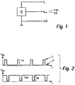
- a sensor 10 is shown, which can be used in a transmission control of a motor vehicle.
- the sensor 10 may be a mechanical, electromagnetic, capacitive or based on other measurement principles sensor.
- the sensor 10 is acted upon by a supply voltage Vs and is connected to ground GND.
- the supply voltage Vs may occupy, for example, a value between about 3 volts and about 12 volts in a motor vehicle, the ground GND corresponds to 0 volts.
- the sensor 10 supplies a signal voltage Vout. This signal voltage Vout may be supplied to the aforementioned transmission control and used there to determine the gear position.
- the sensor 10 is intended to detect two states.
- the signal voltage Vout can therefore also have two states, namely the signal "high” and the signal "low”.
- the sensor 10 is designed such that the two possible signals “high” and “low” of the signal voltage Vout differ from the supply voltage Vs and ground GND.
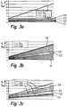
- the two possible signals “high” and “low” of the signal voltage Vout for a first embodiment of the sensor 10 are shown.
- the two signals "high” and “low” are formed as pulse width modulated signals.
- the low signal has an on / off ratio of 20/80 by way of example, while the high signal has an on / off ratio of 80/20.
- the two signals "high” and “low” are generated by the sensor 10 with the aid of a corresponding electrical circuit as a function of the switching position of the sensor 10.
- the signal voltage during operation of the sensor 10 has an on / off ratio of about 20/80, this corresponds to the low signal. If the signal voltage has an on / off ratio of about 80/20, this corresponds to the high signal. Other on / off ratios indicate a fault of the sensor 10.
- on / off ratios can also be chosen differently. At a On / off ratio of 99/1 or 1/99, it is possible to use the temporally successive occurring, short positive or negative pulse for the purpose of diagnosis. Meet such pulses continuously, so there is at least so far no error, the pulses remain off, it can be concluded that an error of the sensor 10.
- FIGS. 3a to 3c the two possible signals “high” and “low” of the signal voltage Vout are shown for further embodiments of the sensor 10.
- the two signals "high” and “low” are defined by predetermined voltage ranges.
- These limits G1, G2, G3, G4 are independent of the supply voltage Vs. The same applies to the specified voltage ranges of the two signals "high” and "low”.
- the limits G2, G3, G4 are dependent on the supply voltage Vs. The same applies to the specified voltage ranges of the two signals "high” and "low”. It is understood that the values given for the calculation of the limits G1, G2, G3, G4 can also be chosen differently.
Landscapes
- Engineering & Computer Science (AREA)
- General Engineering & Computer Science (AREA)
- Mechanical Engineering (AREA)
- Physics & Mathematics (AREA)
- General Physics & Mathematics (AREA)
- Control Of Transmission Device (AREA)
- Gear-Shifting Mechanisms (AREA)
- Measurement Of Length, Angles, Or The Like Using Electric Or Magnetic Means (AREA)
Claims (2)
- Capteur (10) pour la commande de la transmission, notamment d'un véhicule automobile,
le capteur (10) pouvant être raccordé à une tension d'alimentation (Vs) et à la masse (GND),
le capteur (10) formant une tension de signal (Vout) et la tension de signal (Vout) pouvant prendre deux signaux (haut, bas),
les deux signaux (haut, bas) étant différents de la tension d'alimentation (Vs) et de la masse (GND),
les deux signaux (haut, bas) étant définis par des plages prédéfinies de tension (figures 3a à 3c),
les plages de tensions des deux signaux (haut', bas) étant définies par des limites prédéterminées (G1, G2, G3, G4),
caractérisé en ce que
une ou plusieurs des limites (G1, G2, G3, G4) dépendent de la tension d'alimentation (Vs). - Capteur (10) selon la revendication 1, caractérisé en ce qu'il est utilisé comme contacteur de position pour la commande de la transmission d'un véhicule automobile.
Applications Claiming Priority (2)
| Application Number | Priority Date | Filing Date | Title |
|---|---|---|---|
| DE102004024954A DE102004024954A1 (de) | 2004-05-21 | 2004-05-21 | Sensor für eine Getriebesteuerung insbesondere eines Kraftfahrzeugs |
| PCT/EP2005/051563 WO2005114006A1 (fr) | 2004-05-21 | 2005-04-08 | Capteur pour commande de boite de vitesses, en particulier montee dans un vehicule automobile |
Publications (2)
| Publication Number | Publication Date |
|---|---|
| EP1753983A1 EP1753983A1 (fr) | 2007-02-21 |
| EP1753983B1 true EP1753983B1 (fr) | 2017-09-20 |
Family
ID=34963799
Family Applications (1)
| Application Number | Title | Priority Date | Filing Date |
|---|---|---|---|
| EP05731952.7A Expired - Lifetime EP1753983B1 (fr) | 2004-05-21 | 2005-04-08 | Capteur pour commande de boite de vitesses, en particulier montee dans un vehicule automobile |
Country Status (7)
| Country | Link |
|---|---|
| US (1) | US8006547B2 (fr) |
| EP (1) | EP1753983B1 (fr) |
| JP (1) | JP2007538209A (fr) |
| CN (1) | CN1957196B (fr) |
| DE (1) | DE102004024954A1 (fr) |
| HU (1) | HUE035251T2 (fr) |
| WO (1) | WO2005114006A1 (fr) |
Families Citing this family (5)
| Publication number | Priority date | Publication date | Assignee | Title |
|---|---|---|---|---|
| JP4968069B2 (ja) * | 2005-07-19 | 2012-07-04 | 株式会社安川電機 | 異常検出装置付きエンコーダおよびその制御システム |
| DE102005061865A1 (de) | 2005-12-23 | 2007-07-05 | Robert Bosch Gmbh | Verfahren zur Erhöhung der Informationsdichte in Signalübertragungsleitungen |
| DE102007026601B3 (de) | 2007-05-25 | 2008-12-24 | Pierburg Gmbh | Verfahren zur Rückmeldung von Zuständen einer elektrischen Komponente an ein Motorsteuergerät einer Verbrennungskraftmaschine |
| DE102008004454B4 (de) * | 2008-01-15 | 2020-02-13 | Asm Automation Sensorik Messtechnik Gmbh | Winkelsensorschaltung |
| DE102011081147A1 (de) | 2011-08-17 | 2013-02-21 | Robert Bosch Gmbh | Sensormodul zur Erfassung eines Betriebsparameters, Verfahren zur Überwachung eines Sensormoduls und Kombinationssignal |
Family Cites Families (27)
| Publication number | Priority date | Publication date | Assignee | Title |
|---|---|---|---|---|
| US3919703A (en) * | 1974-04-08 | 1975-11-11 | Bertea Corp | Fault detection system for transducers |
| DE3807881A1 (de) * | 1988-03-10 | 1989-09-21 | Porsche Ag | Schaltvorrichtung fuer ein automatikgetriebe eines kraftfahrzeugs |
| GB2255410B (en) * | 1991-05-01 | 1994-05-18 | Ford Motor Co | Digital sensors |
| US5767769A (en) * | 1995-07-28 | 1998-06-16 | Chrysler Corporation | Method of displaying a shift lever position for an electronically-controlled automatic transmission |
| US6002338A (en) * | 1997-09-15 | 1999-12-14 | Ford Global Technologies, Inc. | Method and system for detecting failures in self-exciting sensor |
| JPH11223639A (ja) | 1998-02-05 | 1999-08-17 | Unisia Jecs Corp | 回転速度検出装置 |
| DE19905627B4 (de) * | 1998-02-16 | 2008-09-25 | Luk Gs Verwaltungs Kg | Getriebe für ein Kraftfahrzeug mit einer Wähleinrichtung |
| SE521749C2 (sv) * | 1999-07-02 | 2003-12-02 | Inmotion Technologies Ab | Servostyrsystem för fordon innefattande en digital vinkelavkännande anordning |
| EP1119719A4 (fr) * | 1999-08-06 | 2006-08-23 | Stoneridge Control Devices Inc | Systeme de selection de la position engagee de la transmission |
| JP2001165944A (ja) | 1999-09-30 | 2001-06-22 | Toyota Motor Corp | センサの異常検出方法 |
| DE19959616A1 (de) * | 1999-12-10 | 2001-06-13 | Volkswagen Ag | Steuereinrichtung für ein automatisch und manuell schaltbares Schaltgetriebe in einem Kraftfahrzeug |
| JP3491587B2 (ja) * | 1999-12-21 | 2004-01-26 | 株式会社デンソー | 回転角度検出センサのフェイルモード調整方法 |
| US6316936B1 (en) * | 1999-12-21 | 2001-11-13 | Visteon Global Technologies, Inc. | Linear position sensor for a transmission manual valve |
| JP2001208812A (ja) | 2000-01-26 | 2001-08-03 | Hitachi Ltd | モータ回転角度情報の故障診断方法及び装置 |
| JP2002048230A (ja) | 2000-08-03 | 2002-02-15 | Niles Parts Co Ltd | 自動変速機の調整システム |
| DE10049307B4 (de) * | 2000-10-04 | 2013-01-31 | Volkswagen Ag | Sensorik-System für die Steuereinrichtung eines automatisch schaltbaren Getriebes |
| US7208939B2 (en) * | 2001-02-28 | 2007-04-24 | Bvr Technologies Co. | Methods and apparatus for sensing angular position and speed of a rotatable shaft utilizing linearized annular magnet and commutated ratiometric hall sensors |
| JP3697610B2 (ja) | 2001-05-31 | 2005-09-21 | 東洋電装株式会社 | エンコーダ |
| DE10154642C1 (de) * | 2001-11-07 | 2003-07-17 | Siemens Ag | Auswerteschaltung für einen induktiven Sensor |
| KR100525573B1 (ko) * | 2002-03-26 | 2005-11-02 | 봇슈 가부시키가이샤 | 차량의 구동열에 대한 제어 방법 및 장치와 차량용 자동변속 장치 |
| DE10227633B4 (de) | 2002-06-21 | 2007-08-09 | Audi Ag | Codierter Getriebepositionsschalter |
| JP4356353B2 (ja) * | 2002-12-27 | 2009-11-04 | アイシン・エィ・ダブリュ株式会社 | ポジション判断装置、ポジション判断方法及びプログラム |
| JP4275647B2 (ja) * | 2005-05-11 | 2009-06-10 | 三菱電機株式会社 | 内燃機関の燃料噴射制御装置 |
| JP4344343B2 (ja) * | 2005-06-15 | 2009-10-14 | 本田技研工業株式会社 | 自動変速機のシフト装置 |
| US7443308B2 (en) * | 2006-03-16 | 2008-10-28 | Adc Dls Systems, Inc. | Enhanced AC immunity in ground fault detection |
| US7568402B2 (en) * | 2006-08-04 | 2009-08-04 | Gm Global Technology Operations, Inc. | Method and apparatus for fault-tolerant transmission gear selector lever position determination |
| US7701203B2 (en) * | 2007-05-11 | 2010-04-20 | Caterpillar Inc. | Method of sensing a position of a movable component of an operator interface in a machine |
-
2004
- 2004-05-21 DE DE102004024954A patent/DE102004024954A1/de not_active Withdrawn
-
2005
- 2005-04-08 HU HUE05731952A patent/HUE035251T2/hu unknown
- 2005-04-08 EP EP05731952.7A patent/EP1753983B1/fr not_active Expired - Lifetime
- 2005-04-08 WO PCT/EP2005/051563 patent/WO2005114006A1/fr not_active Ceased
- 2005-04-08 CN CN2005800163332A patent/CN1957196B/zh not_active Expired - Lifetime
- 2005-04-08 US US11/597,874 patent/US8006547B2/en active Active
- 2005-04-08 JP JP2007517220A patent/JP2007538209A/ja active Pending
Non-Patent Citations (1)
| Title |
|---|
| None * |
Also Published As
| Publication number | Publication date |
|---|---|
| DE102004024954A1 (de) | 2005-12-08 |
| EP1753983A1 (fr) | 2007-02-21 |
| WO2005114006A1 (fr) | 2005-12-01 |
| HUE035251T2 (hu) | 2018-05-02 |
| US20090235727A1 (en) | 2009-09-24 |
| JP2007538209A (ja) | 2007-12-27 |
| CN1957196B (zh) | 2010-12-22 |
| US8006547B2 (en) | 2011-08-30 |
| CN1957196A (zh) | 2007-05-02 |
Similar Documents
| Publication | Publication Date | Title |
|---|---|---|
| EP1240446B1 (fr) | Unite de commande pour une boite de vitesses pouvant etre utilisee de maniere automatique et manuelle, installee dans un vehicule automobile | |
| EP1238214B1 (fr) | Systeme de detection destine au dispositif de commande d'une boite de vitesses automatique | |
| DE19905627B4 (de) | Getriebe für ein Kraftfahrzeug mit einer Wähleinrichtung | |
| DE102016103629B4 (de) | Steuerverfahren und Steuersystem für einen Schaltmechanismus eines Fahrzeugs | |
| EP1251474B1 (fr) | Capteur à connexion bifilaire utilisant la modulation d'impulsions en largeur | |
| DE102019216643B4 (de) | System zum Lernen einer Position für ein elektrisches shift-by-wire-Schaltsystem | |
| EP1753983B1 (fr) | Capteur pour commande de boite de vitesses, en particulier montee dans un vehicule automobile | |
| EP2446174B1 (fr) | Dispositif de blocage pour un arbre de changement de vitesse | |
| DE10227633B4 (de) | Codierter Getriebepositionsschalter | |
| EP2025975A2 (fr) | Procédé et dispositif sélecteur de vitesse destiné à sélectionner et à commuter une vitesse pour une boîte de vitesses manuelle d'un véhicule | |
| EP0975872B1 (fr) | Systeme d'antidemarrage pour un vehicule a moteur equipe d'une boite de vitesses automatique | |
| EP1317696A1 (fr) | Dispositif d'activation d'un appareil de commande | |
| DE102005061865A1 (de) | Verfahren zur Erhöhung der Informationsdichte in Signalübertragungsleitungen | |
| DE102009038567A1 (de) | Schaltungsanordnung zur Erfassung der Schaltstellungen eines mehrstufigen Schalters | |
| EP1105955B1 (fr) | Circuit de detection d'un courant d'une intensite inadmissible dans un etage final | |
| DE102014012724A1 (de) | Schaltstellungs-Erfassung eines Kraftfahrzeuggetriebe-Gangschalthebels | |
| EP0866932B1 (fr) | Commande de la boite de vitesses, notamment pour une boite de vitesses automatique a commande electrique du type a arbre de renvoi | |
| DE102015209866A1 (de) | Verfahren zur Zustandsüberwachung von zumindest einem Planetenrad eines Planetengetriebes | |
| DE102008044245A1 (de) | Schaltungsanordnung zum Ansteuern eines Sensors | |
| DE102009049220A1 (de) | Sensorvorrichtung und Verfahren zur Erfassung der Position eines in mindestens zwei Richtungen verschiebbaren Hebels, insbesondere Getriebewählhebels in einem Kraftfahrzeug | |
| DE202013004420U1 (de) | System zum Steuern eines automatisch und manuell schaltbaren Getriebes | |
| DE102013218583A1 (de) | Verfahren und Sensorvorrichtung zur Erfassung der Position eines in zwei Richtungen verschiebbaren Gangwahlhebels in einem Kraftfahrzeug | |
| DE102011079849A1 (de) | Schaltvorrichtung für ein automatisches oder automatisiertes Kraftfahrzeug-Getriebe, mit der Schaltvorrichtung betriebenes Kraftfahrzeug-Getriebes und mit der Schaltvorrichtung betriebenes Kraftfahrzeug | |
| EP2116747A2 (fr) | Système de passage de vitesses pour véhicule | |
| DE102020133240B4 (de) | Vorrichtung und verfahren zum steuern eines elektrischen schalthebelsystem |
Legal Events
| Date | Code | Title | Description |
|---|---|---|---|
| PUAI | Public reference made under article 153(3) epc to a published international application that has entered the european phase |
Free format text: ORIGINAL CODE: 0009012 |
|
| 17P | Request for examination filed |
Effective date: 20061221 |
|
| AK | Designated contracting states |
Kind code of ref document: A1 Designated state(s): AT BE BG CH CY CZ DE DK EE ES FI FR GB GR HU IE IS IT LI LT LU MC NL PL PT RO SE SI SK TR |
|
| DAX | Request for extension of the european patent (deleted) | ||
| 17Q | First examination report despatched |
Effective date: 20091029 |
|
| RBV | Designated contracting states (corrected) |
Designated state(s): AT BE BG CH CY CZ DE DK EE ES FI FR GB GR HU IE IS IT LI LT LU MC NL PL PT RO SE SI SK TR |
|
| RBV | Designated contracting states (corrected) |
Designated state(s): DE FR GB HU |
|
| REG | Reference to a national code |
Ref country code: DE Ref legal event code: R079 Ref document number: 502005015717 Country of ref document: DE Free format text: PREVIOUS MAIN CLASS: F16H0061120000 Ipc: G01D0003080000 |
|
| RIC1 | Information provided on ipc code assigned before grant |
Ipc: F16H 59/10 20060101ALI20160512BHEP Ipc: F16H 61/12 20060101ALI20160512BHEP Ipc: G01D 3/08 20060101AFI20160512BHEP Ipc: F16H 59/70 20060101ALI20160512BHEP |
|
| GRAP | Despatch of communication of intention to grant a patent |
Free format text: ORIGINAL CODE: EPIDOSNIGR1 |
|
| INTG | Intention to grant announced |
Effective date: 20170623 |
|
| GRAS | Grant fee paid |
Free format text: ORIGINAL CODE: EPIDOSNIGR3 |
|
| GRAA | (expected) grant |
Free format text: ORIGINAL CODE: 0009210 |
|
| AK | Designated contracting states |
Kind code of ref document: B1 Designated state(s): DE FR GB HU |
|
| REG | Reference to a national code |
Ref country code: GB Ref legal event code: FG4D Free format text: NOT ENGLISH |
|
| REG | Reference to a national code |
Ref country code: DE Ref legal event code: R096 Ref document number: 502005015717 Country of ref document: DE |
|
| REG | Reference to a national code |
Ref country code: FR Ref legal event code: PLFP Year of fee payment: 14 |
|
| REG | Reference to a national code |
Ref country code: HU Ref legal event code: AG4A Ref document number: E035251 Country of ref document: HU |
|
| REG | Reference to a national code |
Ref country code: DE Ref legal event code: R097 Ref document number: 502005015717 Country of ref document: DE |
|
| PLBE | No opposition filed within time limit |
Free format text: ORIGINAL CODE: 0009261 |
|
| STAA | Information on the status of an ep patent application or granted ep patent |
Free format text: STATUS: NO OPPOSITION FILED WITHIN TIME LIMIT |
|
| 26N | No opposition filed |
Effective date: 20180621 |
|
| PGFP | Annual fee paid to national office [announced via postgrant information from national office to epo] |
Ref country code: FR Payment date: 20180424 Year of fee payment: 14 |
|
| PGFP | Annual fee paid to national office [announced via postgrant information from national office to epo] |
Ref country code: HU Payment date: 20180329 Year of fee payment: 14 |
|
| PGFP | Annual fee paid to national office [announced via postgrant information from national office to epo] |
Ref country code: IT Payment date: 20180719 Year of fee payment: 16 |
|
| GBPC | Gb: european patent ceased through non-payment of renewal fee |
Effective date: 20190408 |
|
| PG25 | Lapsed in a contracting state [announced via postgrant information from national office to epo] |
Ref country code: GB Free format text: LAPSE BECAUSE OF NON-PAYMENT OF DUE FEES Effective date: 20190408 Ref country code: HU Free format text: LAPSE BECAUSE OF NON-PAYMENT OF DUE FEES Effective date: 20190409 |
|
| PG25 | Lapsed in a contracting state [announced via postgrant information from national office to epo] |
Ref country code: FR Free format text: LAPSE BECAUSE OF NON-PAYMENT OF DUE FEES Effective date: 20190430 |
|
| PGFP | Annual fee paid to national office [announced via postgrant information from national office to epo] |
Ref country code: DE Payment date: 20240619 Year of fee payment: 20 |
|
| REG | Reference to a national code |
Ref country code: DE Ref legal event code: R071 Ref document number: 502005015717 Country of ref document: DE |