EP1754036B1 - Mikroschlitz-viskometer mit monolithisch integrierten drucksensoren - Google Patents
Mikroschlitz-viskometer mit monolithisch integrierten drucksensoren Download PDFInfo
- Publication number
- EP1754036B1 EP1754036B1 EP05728127.1A EP05728127A EP1754036B1 EP 1754036 B1 EP1754036 B1 EP 1754036B1 EP 05728127 A EP05728127 A EP 05728127A EP 1754036 B1 EP1754036 B1 EP 1754036B1
- Authority
- EP
- European Patent Office
- Prior art keywords
- flow
- channel
- pressure
- liquid
- cavities
- Prior art date
- Legal status (The legal status is an assumption and is not a legal conclusion. Google has not performed a legal analysis and makes no representation as to the accuracy of the status listed.)
- Expired - Lifetime
Links
Images







Classifications
-
- G—PHYSICS
- G01—MEASURING; TESTING
- G01L—MEASURING FORCE, STRESS, TORQUE, WORK, MECHANICAL POWER, MECHANICAL EFFICIENCY, OR FLUID PRESSURE
- G01L13/00—Devices or apparatus for measuring differences of two or more fluid pressure values
- G01L13/02—Devices or apparatus for measuring differences of two or more fluid pressure values using elastically-deformable members or pistons as sensing elements
- G01L13/025—Devices or apparatus for measuring differences of two or more fluid pressure values using elastically-deformable members or pistons as sensing elements using diaphragms
-
- G—PHYSICS
- G01—MEASURING; TESTING
- G01N—INVESTIGATING OR ANALYSING MATERIALS BY DETERMINING THEIR CHEMICAL OR PHYSICAL PROPERTIES
- G01N11/00—Investigating flow properties of materials, e.g. viscosity, plasticity; Analysing materials by determining flow properties
- G01N11/02—Investigating flow properties of materials, e.g. viscosity, plasticity; Analysing materials by determining flow properties by measuring flow of the material
- G01N11/04—Investigating flow properties of materials, e.g. viscosity, plasticity; Analysing materials by determining flow properties by measuring flow of the material through a restricted passage, e.g. tube, aperture
- G01N11/08—Investigating flow properties of materials, e.g. viscosity, plasticity; Analysing materials by determining flow properties by measuring flow of the material through a restricted passage, e.g. tube, aperture by measuring pressure required to produce a known flow
Definitions
- This invention is in the field of miniature devices that measures true viscosities of liquid.
- Viscosity is a measure of resistance of liquid to flow and its value depends on the rate of deformation for Non-Newtonian liquids as described in Dynamics of Polymeric Liquids, Vol. 1, 1987 authored by R.B. Bird, R.C. Armstrong, and O. Hassager .
- the rate of deformation is given by a shear rate in a unit of (time) -1 .
- the viscosity measured at a known shear rate is "true" viscosity.
- the dependence of the true viscosity on shear rate is a viscosity curve which characterizes material and is an important factor to consider for efficient processing. But in many cases viscosity is measured under ill-defined test conditions so that shear rate can not be known or calculated.
- the measured viscosity value is only "apparent". Since the true viscosity is measured at a known shear rate, the true viscosity is universal whereas the apparent viscosity is not. Instead, the apparent viscosity depends on the measuring system. For example, as a common practice, a torque of a spindle immersed in a sea of test liquid is measured while the spindle is being rotated at a constant speed. In this case the torque value only yields an apparent viscosity since the test condition is ill defined and a shear rate is not known. At best, the apparent viscosity can be measured as a function of the rotational speed of the spindle.
- the rotational speed of the spindle can be, in fact, correlated with the shear rate only if a "constitutive equation" for the test liquid is known.
- a "constitutive equation” is not known for almost all Non-Newtonian liquids. Therefore, true viscosity can not be measured with ill-defined test condition for most non-Newtonian liquids.
- the rheometers impose a precise and known shear rate on test samples thereby measuring true viscosities.
- the rheometers are versatile and equipped to measure other properties. Therefore they are usually expensive. Usually large amounts of sample are required for viscosity measurement with rheometers. Also, the rheometers are not well suited for on-line applications.
- Circular capillary viscometers are another type of instrument that can measure apparent and true viscosities depending on whether a proper compensation is taken into account. The capillary viscometer needs a measurement of pressure drop along the capillary for determining viscosity. Since the capillary is circular, only the pressure at the entrance and exit can be measured.
- capillary viscometer measures only apparent viscosity unless the entrance effect is corrected by using two different capillaries with different length to diameter ratios.
- the use of two capillaries makes the viscometer bulky and measurements time consuming.
- Capillary viscometers are shown in prior art: Patent Nos. 6,575,019 (Larson ); 4,920,787 (Dual et al. ); 4,916,678 (Johnson et al. ); and 4,793,174 (Yau ).
- Microfluidic viscometers were also disclosed in prior arts: 6,681,616 (Michael Spaid et al. ); 20030182991 (Michael Spaid et al. ). Residence time of a marker in a fluidic channel is used to measure the viscosity, which is not a true viscosity unless the test liquid is Newtonian.
- Rectangular slit viscometers relevant to the current invention are also used to measure the true viscosity and they are well described in Rheology in Polymer Processing, 1976, authored by C.D. Han .
- test liquid flows inside of a rectangular slit flow channel and local pressures along the flow channel are measured with deployed pressure sensors for a given flow rate.
- the inside of the slit is flat so that pressures in the slit can be measured with pressure sensors mounted in the slit.
- the positions of the pressure sensors have to be sufficiently inside of the flow channel so that pressures of a fully developed flow are measured. From the pressure measurement, wall shear stress can be calculated. As the flow rate is varied, shear rate can be varied.
- micro slit viscometers allow the employment of microfabrication processes used to make micro chips and therefore these micro slit viscometers can be made in large quantity on a single wafer. This invention therefore makes the micro slit viscometers extremely cost-effectve.
- US 2003/0079547 A1 discloses a rheometer plate with monolithically integrated pressure sensors forming a smooth sensing surface.
- the rheometer plate includes a plurality of cavities. A single capacitive pressure sensor is formed in each cavity. The pressure applied to the rheometer plate leads to a deflection of the surface over the cavity. This deflection leads to a change in the capacity of the pressure sensor.
- US 2003/0079547 A1 also discloses a slit rheometer that comprises a flow channel with multiple cross sections.
- a rheometer plate with multiple pressure sensors is integrated in the flow channel.
- the disclosed rheometers allow measuring the viscosity of a fluid with just one single rheometer of that kind.
- the rheometer is obtained by etching the flow channel in a wafer and then by bonding it to a rheometer plate.
- the drawback of a slit rheometer of that kind is the complicated etching process of the flow channel. Another problem that occurs is that the part in the flow channel where the cross section changes leads to turbulences.
- US 5485753 discloses a pressure sensor consisting of a diaphragm covering a cavity.
- the diaphragm can be constructed using wafer bonding techniques, The cavity allows the diaphragm to bend if pressure is applied to the diaphragm. Piezo resistive strips are used to read out the deformation of the diaphragm.
- the pressure sensor can be used to measure relative pressure changes of 10 to 15 PSI on an absolute pressure base of around 3000 PSI.
- the thickness of a diaphragm, of around 15 microns is suitable in high pressure environment but does not allow the meausurement of small pressures that appear in a micro slit Viscometer.
- the preaaure sensors shown in US 5485753 are stand alone pressure sensors. When integrated into an environment with a flow the sensors cause turbulence in the pipes or flow channels they are attached to.
- US 4241602 teaches a precision continuous flow rheometer.
- the flow rheometer is used to measure large samples in production processes.
- a metering pump receives the fluid to be analyzed from a feed stream.
- the fluid is the applied to a slit or capillary.
- Pressure sensors are provided in the slit, or the capillary.
- the sensors measure a pressure drop along the capillary.
- the pressure sensors in the rheometer are not monolithically integrated into the slit or capillary. This causes turbulances. A fully developed flow will not occur; hence the measured viscosity will be inaccurate.
- the shown flow rheometer is not suited for small samples of fluids.
- a significantly smooth interior surface of a pressure sensing area is ensured by fabricating a monolithic array of pressure sensors and combining it with separately micro-fabricated flow channels.
- the smooth interior surface ensures that the slit flow is less perturbed and the accurate local pressures are measured and the interior surface is less likely damaged by a deposition of test materials.
- the slit flow channel is constructed in a micrometer scale so that only a miniscule amount of sample is required for viscosity measurement.
- the pressure sensors and flow channels are fabricated on wafers using batch microfabrication processes of Micro-Electro-Mechanical Systems. Such a batch wafer process makes many identical parts at the same time and thereby reduces manufacturing costs of the micro viscometers.
- the slit viscometer includes a flow cell and a pumping system capable of causing flow in a controlled manner.
- the flow cell further consists of a microfabricated flow channel with an order of micrometer in depth for flow and monolithic pressure sensor arrays.
- the depth of the channel or channels is in the order of one micrometer, the length of the channel is longer than one hundred micrometers, and the width is wider than ten micronmeters.
- the flow channels are fabricated on a wafer in a known batch process.
- the monolithic pressure sensor arrays are also fabricated on a wafer or wafers.
- the microfabricated wafer with many flow channels is combined with the microfabricated wafer with many monolithic pressure sensor arrays in a known manner.
- the combined wafer has many flow cells, which are further diced to separate individual flow cells.
- a test liquid is pumped to flow from one end of the flow channel to the other end and resulting pressure drop along the flow channel is measured.
- a preferred method is to form the flow channel by etching wafers such as silicon (Si), Galum Arsenide (GaAs), borosilicate (Pyrex 7740), or derivatives of these materials in a known manner.
- etching wafers such as silicon (Si), Galum Arsenide (GaAs), borosilicate (Pyrex 7740), or derivatives of these materials in a known manner.
- a fabrication method to form pressure sensors is to form a plurality of cavities on a plate so that the smooth measuring surface of the plate extends over the cavities to form an end of the cavity which will deform slightly in response to pressure applied to the smooth surface over the cavity.
- a single and simple detection mechanism is formed on each cavity to provide a measurement of pressure applied by the liquid under test against the surface over the cavity.
- the detection mechanism is capacitive, piezo-resistive, or optical.
- the primary object of present invention is to provide a micro slit flow viscometer consisting of flow channels combined with monolithic pressure sensor arrays to measure true viscosities with a miniscule amount of sample.
- Another objective of this invention is that the flow channels and pressure sensors are fabricated on wafers commonly used in microfabrication and they are combined in order to mass produce viscometers in a cost effective manner.
- FIG. 1 and 2 An embodiment of a micro slit flow cell of the invention is shown in Figures 1 and 2 and includes a flow entrance or inlet 20, a flow exit or outlet 21, and a flow channel 22 therebetween.
- the flow channel 22 has a predetermined uniform depth (gap) in the micrometer range along the channel.
- the width of the channel is significantly larger than the depth of the channel so that the flow through the channel can be considered to be a one-dimensional problem instead of a two dimensional problem.
- the ratio of the width to the depth is preferably larger than ten.
- the preferred depth of the channel is in the order of a micrometer.
- the preferred length of the channel is at least one hundred micrometers excluding the entrance and exit zones, 23 and 24, respectively.
- the test liquid is forced to flow through the flow channel 22 of the micro slit flow cell by a pumping system, not shown, at a controllable constant volumetric flow rate.
- a pumping system for small volumes is preferably used.
- a micro syringe pump is one of several possible pumping system. Micro syringe pumps are readily available and a selected micro syringe pump, not shown, is connected to the inlet 20 of the flow cell in a known manner. A drain or drain system, also not shown, is connected to the exit or outlet 21 in a known manner.
- pressure sensors are located in pressure sensor cavities 26 positioned at different locations along the flow channel 22 away from the entrance and the exit zones.
- the pressure sensors measure the pressure of the flowing liquid in the flow channel 22 at the location of the respective cavity 26.
- at least two pressure sensor cavities 26 with associated pressure sensors are positioned along the flow channel 22, four such pressure sensor cavities being shown in Figures 1 and 2 . Liquid viscosity is known to be very sensitive to temperature.
- a temperature sensor cavity 28 is located along the flow channel near the entrance zone. If desired, an additional temperature sensor cavity, not shown in Figures 1 and 2 , can be located near the exit zone to monitor the temperature uniformity or provide temperture change information to be used in correcting the viscosity measurements obtained.
- bond pads 29 are located in a manner so that the necessary electrical connections to the pressure sensors, temperature sensors, and other sensors that may be provided can be made in a simple manner, for example to a micro-controller based PCB (printed circuit board) read out circuit through wire bonding or other surface mounting technology.
- Flow into the entrance 20 and from the exit 21 can be made to be perpendicular to the flow channel 22 as shown in Figure 2 , or parallel to the flow channel 22 as shown in Figure 3 , depending on the desired channel and cell configurations and interfaces with the pumping system at the entrance and with the drain system at the exit.
- the flow cell includes a flow channel substrate 30 and a sensor plate formed of a sensor membrane 31 and a sensor substrate 32.
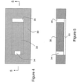
- the flow channel substrate 30 has a cavity 33, Figures 4 and 5 , which forms the flow channel 22 when the substrate is combined with the sensor plate, as shown in Figures 2 and 3 .
- the flow channel substrate 30 may also have an inlet hole 34 which forms the channel entrance 20 and an outlet hole 35 which forms the channel exit 21.
- the sensor membrane 31 forms a monolithic, substantially smooth flow channel pressure sensing surface 36 along one side of the flow channel 22, shown as the bottom channel surface in the orientation of Figures 2 and 3 .
- the pressure sensors and temperature sensors are preferably integrated into the sensor plate so a monolithically integrated array of pressure sensors with one or more temperature sensors is formed.
- the monolithic pressure sensing surface 36 provides a sufficiently smooth flow channel pressure sensing surface to provide more accurate pressure measurements and potentially longer service than if the pressure sensors were individually and separately placed on or in the pressure sensing surface.
- the flow channel substrate 30 has a cavity 33 with well defined pre-determined depth as shown in Figure 4 and 5 .
- the cavity can be formed by etching the substrate after photo-resist on the substrate is patterned using the known photolithography processes of micro-fabrication processes.
- the etching method can be wet chemical etching or plasma dry etching. These etching processes are made on a wafer level so that many cavities can be formed simultaneously.
- borosilicate glasses Pyrex 7740
- Silicon silicon
- GaAs or other materials used in microfabrication processes can be used. Etching of these wafers can be done in a known manner.
- the Pyrex is etched with buffered hydro fluoric acid solution or Buffered Oxide Etcher (BOE) to form the cavity 33.
- Buffered Oxide Etcher Buffered Oxide Etcher
- the inlet or entrance hole 34 and the outlet or exit hole 35 can be made by ultrasonic cutting, other mechanical machining, or by etching.
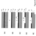
- Figure 6 shows an alternate method for forming the flow cavity 33 in the flow channel substrate 30.
- a Pyrex wafer 40 with holes, not shown, for the entrance and exit is bonded to the device silicon 41 of an SOI (silicon-on-insulator) wafer, which consists of device silicon 41, buried oxide 42, and handle silicon 43, using conventional nomenclature.
- This is shown in 6A.
- the handle silicon 43 is etched away to give the wafer formation of 6B.
- the exposed oxide layer 42 is patterned as at 44, 6C, for subsequent etching of the device silicon layer 41 to form a cavity 45, 6D.
- the oxide layer is removed to give the flow channel substrate of 6E.
- the cavity can be formed on a silicon wafer by first oxidizing the silicon. The oxide is patterned to form etch masks. Then the exposed silicon is etched to form cavities in a known manner. The remaining oxide is removed subsequently.
- the sensor plate consists of pressure sensor membrane 31 and a pressure sensor substrate 32. At the interface between the membrane 31 and the substrate 32, there are cavities for pressure sensing and for temperature sensing.
- the cavities can be formed in the back or underside of the pressure sensor membrane, in the pressure sensor substrate, or in both.
- the portion of the membrane which extends over each cavity deflects as pressure is applied to the pressure sensing surface 36 over the cavity and the amount of deflection of the membrane into the cavity is measured to provide an indication of the pressure applied to the pressure sensing surface over the cavity.
- Figures 2 , 3 , 8, and 9 show pressure sensor cavities 26 and temperature sensor cavities 28 formed in the back or underside of the pressure sensor membrane 31.
- the deflection of the portion of the pressure sensor membrane that extends over a cavity, indicated as 48 in Figure 9 can be measured by a capacitance change, resistance change, optical path change, or other type pressure sensor, as desired.
- Figure 9 shows a capacitacnce pressure sensor which measures a capacitance change as the portion of the membrane 48 over the pressure sensor cavity 26 deforms under different pressures applied by a test liquid flowing over membrane portion 48.
- cavity 26 has two sides, 50 and 51, and each side 50 and 51 has an electrode 52 and 53, respectively, mounted thereto.
- An insulating layer 54 separates upper electrode 52 from the pressure sensor membrane material, while lower electrode 53 is mounted directly to the pressure sensor substrate.
- Insulating material 55 is provided on the upper face of capacitor lower electrode 53 to prevent shorting of the electrodes under pressure that would deform the membrane portion 48 enough to cause electrode 52 to otherwise contact electrode 53.
- the capacitance of the two electrodes depends upon the separation of the electrodes and changes as the gap or distance between the electrodes change as the membrane portion 48 over the cavity deflects under pressure.
- the sensor plate is fabricated on a wafer using micro-fabrication processes.
- the pressure sensor substrate 32 can be prepared by processing a Pyrex wafer as shown in Figures 10 and 11 . Chrome or Titanium, and Platinum are deposited in sequence and are patterned to form temperature sensors 57 on the surface of the Pyrex. Bottom capacitor electrodes 53 and electrical leads 58 are formed by depositing metal on patterned resist on the Pyrex. The resist is lifted off to leave patterned metals. If desired, the Pyrex can be etched slightly before depositing metals using the patterned resist as etch mask so that most of the metals deposited are embedded in the Pyrex. Oxide is then deposited over the capacitor electrodes to form insulating material 55. The Pyrex can be ultrasonically machined to form vias 60.
- the pressure sensor membrane can be made using an SOI wafer, for example.
- an SOI (silicon-on-insulator) wafer consists of device silicon 41, buried oxide 42, and handle silicon 43.
- the SOI wafer does not include the pyrex 40 shown in Figure 6A .
- the device silicon which becomes the pressure sensor membrane material 31, is etched to form the desired pressure sensor cavities 26 and temperature sensor cavities 28 on the underside of the membrane using patterned oxide as an etch mask.
- the oxide is then removed and a fresh oxide layer to form insulating material 54 is grown on the device silicon.
- Metal is then deposited on patterned resist on the oxide layer over the device silicon of the SOI.
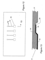
- the resist is removed to form the capacitor upper electrodes 52 and to form electrical leads 61, Figure 13 , separated from the device silicon 31 by the insuling oxide layer 54.
- the processed SOI wafer for forming the pressure sensor membrane is then bonded to the processed Pyrex wafer forming the pressure sensor substrate.
- Metal is then deposited using an aperture mask on the bottom of the pyrex pressure sensor substrate to form the bond pads 29, Figure 11 , and electrical connectivity 62 along vias 60 to connect with leads 58. Then remove The handle silicon and buried oxide layer of the SOI wafer forming the membrane is then removed in sequence to finish formation of the pressure sensor plate.
- Figure 14 shows a pressure sensor cavity 64 formed in the pressure sensor substrate 65 rather than in the pressure sensor membrane 66.
- a capacitor upper electrode 67 and electrical lead 68, and an insulating layer 69, are formed on the flat bottom surface (no wells) of the pressure sensor membrane 66.
- Capacitor lower electrode 70 and electrical lead 71 are formed in the well 64 and on the surface of the pressure sensor substrate 65.
- Insulating material 72 is deposited on capacitor lower electrode 70.
- This forms a pressure sensor plate similar to that described for prior figures, and operates similarly to detect and measure the deflection of membrane 66 into cavity 64.
- the difference is that the pressure sensor cavity is formed in the pressure sensor substrate rather than in the pressure sensor membrane, and the pressure sensor membrane will be of a uniform thinner thickness.
- the temperature sensor cavities in this embodiment will similarly be formed in the substrate rather than in the membrane.
- the semi-conductor membrane membrane portion 48 in Figure 9 and membrane 66 in Figure 14
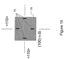
- the semi-conductor membrane is properly doped in a known manner to form resistors 75, Figure 15 , where the membrane is indicated as 76.
- the resistance changes of the doped resistors 75 on the membrane 76 as the membrane is deflected into a cavity, are measured in a known manner.
- resistances of the doped regions change and the changes are measured in, for example, a Wheatstone-bridge configuration of the resistors.
- p-type piezoresistors are formed along the ⁇ 110> directions on an n-type (100) silicon wafer 76 as shown in Figure 15 .
- These conventional piezo-resistive silicon sensors are not suitable for high temperature applications above 120 °C. With temperatures above 120 °C, the p-n junctions leaks current. In order to prevent the current leakage and increase the service temperature for these conventional piezo-resistive silicon sensors, the p-n junctions can be isolated by putting insulators between the p-n junctions or using a SOI (silicon-on-insulator) in a known manner. Alternately, wide band gap materials such as GaAs or SiC can be used for the membrane materials.
- the combined wafers forming the pressure sensor plate and the wafer forming the flow channel substrate are then joined and bonded together in a known manner depending on the chosen material combinations for the pressure sensor plate and the flow channel substrate to form a wafer with completed micro flow cells as shown in Figures 1, 2 , and 3 .
- the bonding method could be glass-frit, thermal compression, eutectic bonding, anodic bonding, or other methods.
- micro-fabrication processes such as those described as examples, many flow cells can be made on a single combined wafer, and many such wafers can be made in a batch, all in a very cost effective manner. Since many flow cells can be made on each wafer, the combined wafer forming the completed flow cells can be diced to separate the flow cells into individual flow cells or into pieces containing a desired number of individual flow cells.
- a wafer with flow channel substrates is bonded first with the SOI wafer. Then the handle Si and oxide are sequentially removed. The exposed device Si wafer is processed to form a plurality of sensor membranes. A Pyrex 7740 wafer with plurality of pressure sensor substrates is separately processed. Then the two wafers are combined preferably with an anodic bonding process. The bonded wafers are then diced for individual viscosity sensors after vias are processed appropriately.
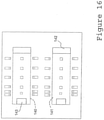
- each flow cell may have two or more flow channels in parallel as shown in Figure 16.
- Figure 16 shows two parallel flow cells 140 and 141.
- Such flow cells can be formed by dicing the wafer containing the flow cells so that a diced piece includes two or more parallel cells. Where two or more flow cells are used, separate pumps may be used for each different cell. This is shown schematically in Figure 17 .
- Pump 145 pumps test liquid through conduit 146 to cell 147.
- Pump 148 pumps test liquid through conduit 149 to cell 150. If the channels of the cells are the same size and the same test fluid is used in each cell, true viscosity can be measures by running pump 145 to pump fluid at one rate through flow cell 147 and running pump 148 to pump the fluid at a different rate through cell 150.
- True viscousity can be measured by running the pump at constant flow rate and switching between flow cells if the flow channels of the flow cells are of different size. With the same size flow channels in the cell, true viscosity can be measured if the valves 158 and 159 are replaced by flow controllers so that flow from the pump will simultaneously flow at controlled known rates through both cells 156 and 157.
- parallel flow cells can be connected appropriately with flow channels or conduits, or other connections, to form channels connected in series.
- the outlet 142 of channel 141 may be connected to the inlet 143 of channel 140 in Figure 16 .
- Such series connected channels may have different channel sizes so that, in effect, a series channel of different sizes or flow volumes is created.
- each liquid to be mixed such as pumps 160 and 161 in Figure 19
- the output conduits 162 and 163 from each pump being joined so that the liquids from each pump mix in conduit 164 directing the mixed liquids to cell 165.
- the ratio of the mixed components is controled by controlling the relative pumping rate of the two pumps 160 and 161.
- Inventions described in Figures 1 , 7 , 10 , and 15 have bond pads located at the bottom of the pressure sensor substrate so that the bond pads are connected to the detection circuitries.
- this bond pad configuration may not be desirable for certain applications. Instead, the bond pads may be positioned on the top of the pressure sensor substrates beyond flow channels so that they are exposed. The exposed pads are wire bonded further to the detection circuitry. To make this bond pad configuration, the conductor leads fabricated on the pressure sensor membrane should be properly transferred to bond pads on the top of the pressure sensor substrate.
- This viscosity sensor can be further integrated with a flow rate sensor.
- the flow sensor measures the flow rate of liquid and the viscosity sensor measures a pressure drop along the flow channel. With the known flow rate and the pressure drop, apparent viscosity can be measured. In order to measure the true viscosity, pressure drops need to be measured for different flow rates. This can be achieved by connecting flow channels with different gaps or by varying flow rates. As the liquid flows through the flow channels, flow rates vary in each channel because of the change in cross-section. The variation in flow rate changes the pressure drop in each channel. From the measured pressure drop for each channel, a true viscosity can be obtained.
- the flow rate sensors that can be used along with the viscosity sensor are hot wire flow rate sensor, acoustic wave flow rate sensor, coriolis flow rate sensor, etc. These sensors are constructed and integrated in a known manner.
Landscapes
- Physics & Mathematics (AREA)
- General Physics & Mathematics (AREA)
- Health & Medical Sciences (AREA)
- Life Sciences & Earth Sciences (AREA)
- Chemical & Material Sciences (AREA)
- Analytical Chemistry (AREA)
- Biochemistry (AREA)
- General Health & Medical Sciences (AREA)
- Immunology (AREA)
- Pathology (AREA)
- Measuring Fluid Pressure (AREA)
- Measuring Volume Flow (AREA)
Claims (13)
- Spaltrheometer zur Bestimmung der Viskositäten von Flüssigkeiten, umfassend: eine monolithische Sensorplatte aus einer Kombination aus einer Drucksensormembran (31) und einem Drucksensorsubstrat (32) mit mindestens zwei Hohlräumen (26), die in der Rück- oder Unterseite der Drucksensormembran (32), in dem Drucksensorsubstrat (32) oder in beiden ausgebildet sind, wobei sich ein Teil der Drucksensormembran (31), der sich über entsprechende Hohlräume (26) der mindestens zwei Hohlräume erstreckt, in die entsprechenden Hohlräume (26) auslenkt, wenn ein Druck auf den Teil der Drucksensormembran (31) über einem entsprechenden Hohlraum ausgeübt wird, wodurch Drucksensoren ausgebildet werden, wobei das Ausmaß der Auslenkung eine Anzeige des Drucks liefert, der auf die Drucksensorfläche über dem Hohlraum (26) ausgeübt wird; ein Kanalsubstrat (30), das so konfiguriert ist, dass es einen einzelnen Flüssigkeitsströmungskanal (22) mit gleichmäßiger Breite, gleichmäßiger Länge und gleichmäßiger Tiefe zwischen einem Flüssigkeitsströmungskanaleingang (23) und einem Flüssigkeitsströmungskanalausgang (24) bildet, wenn es mit der monolithischen Sensorplatte kombiniert ist, wobei die Drucksensormembran (31) eine monolithische, im Wesentlichen glatte Strömungskanaldruckmessfläche (36) entlang einer Seite des Strömungskanals (22) bildet; wobei die Breite des Strömungskanals (22) mindestens etwa zehnmal größer ist als die Tiefe des Strömungskanals und die Tiefe in der Größenordnung eines Mikrometers liegt; und wobei die mindestens zwei Drucksensoren, die in den jeweiligen Hohlräumen (26) angeordnet sind, ausreichend vom Eingang des Flüssigkeitsströmungskanals und vom Ausgang des Flüssigkeitsströmungskanals beabstandet sind, so dass ein Druckabfall der voll entwickelten Strömung der Flüssigkeit durch den Strömungskanal gemessen werden kann.
- Spaltrheometer nach Anspruch 1, das zusätzlich eine Einrichtung aufweist, die eine Strömung einer zu prüfenden Flüssigkeit durch den Flüssigkeitsströmungskanal bewirkt.
- Spaltrheometer nach Anspruch 2, wobei das Mittel zum Erzeugen einer Strömung durch den Flüssigkeitsströmungskanal eine Pumpe (145, 148, 152, 160, 161) ist und wobei während der Flüssigkeitsströmung der von der Flüssigkeit an den Stellen der Drucksensoren ausgeübte Druck von jedem Sensor gemessen wird und aus solchen Messungen die scheinbare Viskosität und die wahre Viskosität bestimmt werden können.
- Spaltrheometer nach Anspruch 3, wobei die Durchflussmenge der Pumpe (145, 148, 152, 160, 161) einstellbar ist.
- Spaltrheometer nach Anspruch 1, wobei die Sensorplatte mindestens einen Temperatursensor (28) für den Strömungskanal aufweist, der zur Messung der Temperatur der durch den Strömungskanal fließenden Flüssigkeit angeordnet ist.
- Verfahren zur Messung der Viskosität einer Flüssigkeit, umfassend:(a) Erhalten eines Spaltrheometers nach Anspruch 4;(b) Einstellen der Pumpe, um eine Testflüssigkeit durch den Flüssigkeitsströmungskanal zu leiten, wobei die Pumpe mit einer Durchflussrate arbeitet und Druckmessungen mit den Drucksensoren vorgenommen werden;(c) Ändern der Durchflussrate der Pumpe, Durchleiten der Testflüssigkeit durch das Spaltrheometer mit einer anderen Durchflussrate und Durchführen von Druckmessungen mit den Drucksensoren; und(d) Bestimmen der tatsächlichen Viskosität der Flüssigkeit aus den Druckmessungen bei den bekannten Durchflussraten.
- Verfahren zum Messen der Viskosität einer Flüssigkeit, umfassend:(a) Bereitstellen eines ersten und eines zweiten Spaltrheometers nach Anspruch 4,(b) Betreiben der Pumpe des ersten Rheometers, um Flüssigkeit mit einer Rate durch den Strömungskanal des ersten Rheometers zu pumpen, und Messen des an den Drucksensoren des ersten Rheometers anliegenden Drucks;(c) Betreiben der Pumpe des zweiten Rheometers, um Fluid mit einer anderen Rate durch den Strömungskanal des zweiten Rheometers zu pumpen, und Messen des an den Drucksensoren des zweiten Rheometers anliegenden Drucks; und(d) Ermitteln der tatsächlichen Viskosität der Flüssigkeit durch Vergleichen und Korrelieren mit den Durchflussraten.
- Verfahren zum Messen der Viskosität einer Flüssigkeit, umfassend:(a) Bereitstellen eines ersten und eines zweiten Spaltrheometers nach Anspruch 2, wobei das erste und das zweite Spaltrheometer Strömungskanäle aufweisen, die durch unterschiedlich dimensionierte Ausnehmungen gebildet werden;(b) Durchleiten von Flüssigkeit durch die Strömungskanäle des ersten Rheometers und des zweiten Rheometers und Messen der Druckdifferenz, die von zwei Drucksensoren in einer besonders dimensionierten Ausnehmung erfasst wird; und(c) Vergleichen der Messungen in unterschiedlich dimensionierten Vertiefungen zur Bestimmung der tatsächlichen Viskosität der Flüssigkeit.
- Verfahren zur Messung der Viskosität einer Flüssigkeit nach Anspruch 8, wobei die erste bekannte Durchflussrate und die zweite bekannte Durchflussrate gleich sind.
- Verfahren zur Messung der Viskosität einer Flüssigkeit nach Anspruch 8, wobei die erste bekannte Durchflussrate und die zweite bekannte Durchflussrate unterschiedlich sind.
- Verfahren zur Herstellung von Spaltrheometern nach einem der Ansprüche 1 bis 5, umfassend:(a) Ausbilden einer Vielzahl von Kanalhohlräumen (33) in einem Kanalsubstrat (30), wobei jeder Kanalhohlraum (33) eine gleichmäßige Breite, eine gleichmäßige Länge und eine gleichmäßige Tiefe sowie eine Längsöffnung entlang einer Verbindungsfläche des Kanalsubstrats aufweist;(b) Bilden einer Vielzahl von Hohlräumen (26) in einer Drucksensormembran (31) und/oder einem Drucksensorsubstrat (32), wobei die Anzahl der Hohlräume (26), die die Vielzahl von Hohlräumen bilden, mindestens doppelt so groß ist wie die Anzahl der in dem Kanalsubstrat (30) gebildeten Kanalhohlräume (33);(c) Kombinieren der Drucksensormembran (31) mit dem Drucksensorsubstrat (32), um eine Drucksensorplatte zu schaffen, wobei sich ein Teil (48) der Drucksensormembran (31) über entsprechende Hohlräume (26) der Vielzahl von Hohlräumen erstreckt;(d) dadurch Bilden von Drucksensoren in der Vielzahl von Hohlräumen (26);(e) Kombinieren der Drucksensorplatte mit dem Kanalsubstrat (30) entlang der Verbindungsfläche des Kanalsubstrats (30), um die Vielzahl von Kanalhohlräumen (33) entlang der Verbindungsfläche des Kanalsubstrats (30) zu schließen, um eine Vielzahl von Strömungskanälen (22) zu erzeugen, die jeweils einen Strömungseingang (20) und einen Strömungsausgang (21) haben, durch die Flüssigkeit fließen kann, wobei jeder Strömungskanal (22) über mindestens zwei der mehreren Drucksensoren in der Drucksensorplatte verläuft, wobei die mindestens zwei Drucksensoren entlang der Länge jedes Strömungskanals (22) ausreichend weit vom Flüssigkeitseintritt (23) und vom Flüssigkeitsaustritt (24) beabstandet sind, wodurch ein Druckabfall der voll entwickelten Flüssigkeitsströmung durch jeden der Strömungskanäle (22) gemessen werden kann; und(f) Trennen der jeweiligen Strömungskanäle der Vielzahl von Strömungskanälen in eine Vielzahl von einzelnen Strömungskanälen, die eine Vielzahl von einzelnen Spaltrheometern umfassen.
- Verfahren zur Herstellung von Spaltrheometern nach Anspruch 11, wobei jeder Kanalhohlraum (33) entgegengesetzte Enden hat und der Strömungseingang (23) sich durch das Kanalsubstrat zu einem Ende des Kanalhohlraums erstreckt und der Strömungsausgang (24) sich durch das Kanalsubstrat zu dem entgegengesetzten Ende des Kanalhohlraums erstreckt.
- Verfahren zur Herstellung von Spaltrheometern nach Anspruch 12, wobei jeder der mehreren Kanalhohlräume (33) drei Kanalwände aufweist und wobei die monolithische Sensorplatte eine vierte Wand für jeden der mehreren Kanalhohlräume bildet, wenn die monolithische Sensorplatte mit dem Kanalsubstrat (30) kombiniert wird, um die mehreren Strömungskanäle (22) zu bilden.
Applications Claiming Priority (2)
| Application Number | Priority Date | Filing Date | Title |
|---|---|---|---|
| US55228904P | 2004-03-11 | 2004-03-11 | |
| PCT/US2005/007869 WO2005086883A2 (en) | 2004-03-11 | 2005-03-11 | Micro slit viscometer with monolithically integrated pressure sesonrs |
Publications (3)
| Publication Number | Publication Date |
|---|---|
| EP1754036A2 EP1754036A2 (de) | 2007-02-21 |
| EP1754036A4 EP1754036A4 (de) | 2008-12-31 |
| EP1754036B1 true EP1754036B1 (de) | 2022-02-16 |
Family
ID=34976211
Family Applications (1)
| Application Number | Title | Priority Date | Filing Date |
|---|---|---|---|
| EP05728127.1A Expired - Lifetime EP1754036B1 (de) | 2004-03-11 | 2005-03-11 | Mikroschlitz-viskometer mit monolithisch integrierten drucksensoren |
Country Status (4)
| Country | Link |
|---|---|
| EP (1) | EP1754036B1 (de) |
| JP (1) | JP4825791B2 (de) |
| CN (1) | CN101124467B (de) |
| WO (1) | WO2005086883A2 (de) |
Families Citing this family (21)
| Publication number | Priority date | Publication date | Assignee | Title |
|---|---|---|---|---|
| JP2537264Y2 (ja) | 1990-12-20 | 1997-05-28 | 松下電工株式会社 | スポットライト |
| US7770436B2 (en) | 2001-10-31 | 2010-08-10 | Rheosense, Inc. | Micro rheometer for measuring flow viscosity and elasticity for micron sample volumes |
| DE102006029285B4 (de) * | 2006-06-23 | 2008-03-13 | Technische Universität Dresden | Sensor zur Messung der Viskosität einer Flüssigkeit |
| FR2907226B1 (fr) * | 2006-10-13 | 2008-12-12 | Rhodia Recherches & Tech | Dispositif d'analyse fluidique,dispositif de determination de caracteristiques d'un fluide comprenant ce dispositif d'analyse,procedes de mise en oeuvre et procede de criblage correspondants |
| JP4845047B2 (ja) * | 2007-08-31 | 2011-12-28 | 独立行政法人産業技術総合研究所 | 粘度計 |
| US7784330B2 (en) * | 2007-10-05 | 2010-08-31 | Schlumberger Technology Corporation | Viscosity measurement |
| EP2406587B1 (de) * | 2009-03-10 | 2020-11-18 | Sensortechnics GmbH | Halbleiterbasierter strömungsmesser mit gehäuse |
| EP2564181B1 (de) * | 2010-04-26 | 2021-08-25 | RheoSense, Inc. | Tragbares viskometer |
| DK2724142T3 (en) * | 2011-06-22 | 2015-12-21 | Univ Danmarks Tekniske | Flow measurement devices and procedure |
| KR101338171B1 (ko) * | 2012-08-29 | 2013-12-06 | 인하대학교 산학협력단 | 마이크로 펌프와 센서를 이용한 유량제어모듈 |
| WO2014094791A1 (en) * | 2012-12-20 | 2014-06-26 | Danmarks Tekniske Universitet | Fluid composition analysis device and method |
| JP5992880B2 (ja) * | 2013-08-26 | 2016-09-14 | 日本電信電話株式会社 | フローセル |
| WO2015157698A1 (en) * | 2014-04-11 | 2015-10-15 | Rheosense, Inc. | Viscometer and methods for using the same |
| DE102016201537B4 (de) * | 2016-02-02 | 2019-05-02 | Leistritz Extrusionstechnik Gmbh | Rheometer |
| JP6762009B2 (ja) * | 2016-08-16 | 2020-09-30 | 国立大学法人九州工業大学 | 体液粘性測定装置 |
| CN111727365A (zh) * | 2017-12-15 | 2020-09-29 | ams 国际有限公司 | 集成的颗粒物传感器系统 |
| JP6759372B2 (ja) * | 2019-01-21 | 2020-09-23 | キユーピー株式会社 | 非ニュートン流体のレオロジー特性値を得る方法及び装置 |
| CN109932283B (zh) * | 2019-04-19 | 2021-07-27 | 常州大学 | 高剪切速率下非牛顿流体表观黏度测量装置及测量方法 |
| CN113188705B (zh) * | 2021-04-30 | 2022-11-25 | 华力创科学(深圳)有限公司 | 一种基于光路阻隔法的小型力传感器及六轴力传感器 |
| EP4337285A4 (de) | 2021-05-10 | 2025-03-26 | RheoSense, Inc. | Viskosimeter mit reduziertem totvolumen und hohem dynamikbereich |
| CN116399486A (zh) * | 2023-03-08 | 2023-07-07 | 歌尔微电子股份有限公司 | 芯片组件、应力处理方法和传感器 |
Family Cites Families (16)
| Publication number | Priority date | Publication date | Assignee | Title |
|---|---|---|---|---|
| US4241602A (en) * | 1979-04-20 | 1980-12-30 | Seismograph Service Corporation | Rheometer |
| US4916678A (en) | 1979-06-29 | 1990-04-10 | Phillips Petroleum Company | Viscometer |
| JPS5745430A (en) * | 1980-09-02 | 1982-03-15 | Japan Synthetic Rubber Co Ltd | Slit die rheometer |
| US4578735A (en) * | 1984-10-12 | 1986-03-25 | Knecht Thomas A | Pressure sensing cell using brittle diaphragm |
| DE3771513D1 (de) | 1986-01-29 | 1991-08-29 | Marukomu Kk | Rotationsviskosimeter. |
| US4920787A (en) | 1987-06-12 | 1990-05-01 | Dual Juerg | Viscometer |
| US4793174A (en) | 1987-10-05 | 1988-12-27 | E. I. Du Pont De Nemours And Company | Differential pressure capillary viscometer |
| EP0616688B1 (de) * | 1991-12-13 | 1996-04-17 | Honeywell Inc. | Entwurf von piezoresistivem drucksensor aus silizium |
| US5317908A (en) | 1992-04-28 | 1994-06-07 | National Metal Refining Company, Inc. | High viscosity transducer for vibratory viscometer |
| US5983727A (en) * | 1997-08-19 | 1999-11-16 | Pressure Profile Systems | System generating a pressure profile across a pressure sensitive membrane |
| DE19750131C2 (de) * | 1997-11-13 | 2002-06-13 | Infineon Technologies Ag | Mikromechanische Differenzdrucksensorvorrichtung |
| JP3873084B2 (ja) * | 1997-12-29 | 2007-01-24 | 財団法人くまもとテクノ産業財団 | 動粘度計 |
| US6575019B1 (en) | 2000-01-14 | 2003-06-10 | Chandler Engineering Company Llc | Reciprocating drive/pump system and reciprocating capillary viscometer utilizing same |
| US6681616B2 (en) | 2000-02-23 | 2004-01-27 | Caliper Technologies Corp. | Microfluidic viscometer |
| US6393898B1 (en) | 2000-05-25 | 2002-05-28 | Symyx Technologies, Inc. | High throughput viscometer and method of using same |
| WO2003038388A1 (en) * | 2001-10-31 | 2003-05-08 | Rheosense, Inc. | Pressure sensing device for rheometers |
-
2005
- 2005-03-11 CN CN2005800148421A patent/CN101124467B/zh not_active Expired - Lifetime
- 2005-03-11 EP EP05728127.1A patent/EP1754036B1/de not_active Expired - Lifetime
- 2005-03-11 WO PCT/US2005/007869 patent/WO2005086883A2/en not_active Ceased
- 2005-03-11 JP JP2007502978A patent/JP4825791B2/ja not_active Expired - Fee Related
Also Published As
| Publication number | Publication date |
|---|---|
| CN101124467A (zh) | 2008-02-13 |
| JP4825791B2 (ja) | 2011-11-30 |
| WO2005086883A2 (en) | 2005-09-22 |
| EP1754036A4 (de) | 2008-12-31 |
| WO2005086883A3 (en) | 2006-11-23 |
| EP1754036A2 (de) | 2007-02-21 |
| JP2007528501A (ja) | 2007-10-11 |
| CN101124467B (zh) | 2011-04-20 |
Similar Documents
| Publication | Publication Date | Title |
|---|---|---|
| US7290441B2 (en) | Micro slit viscometer with monolithically integrated pressure sensors | |
| CN101124467B (zh) | 具有整体集成压力传感器的微缝隙式粘度计 | |
| US7770436B2 (en) | Micro rheometer for measuring flow viscosity and elasticity for micron sample volumes | |
| EP1451546B1 (de) | Druckmesseinrichtung für rheometer | |
| Sammarco et al. | Thermocapillary pumping of discrete drops in microfabricated analysis devices | |
| US9354152B2 (en) | Rheometry apparatus | |
| US10371135B2 (en) | Micropump having a flowmeter, and method for producing same | |
| Srivastava et al. | Electronic drop sensing in microfluidic devices: automated operation of a nanoliter viscometer | |
| US10386282B2 (en) | Method, apparatus and micro-rheometer for measuring rheological properties of newtonian and non-newtonian fluids | |
| CN115541099B (zh) | 一种电容式微流体压力传感器、制备方法及其微流体芯片 | |
| Meng et al. | A parylene MEMS flow sensing array | |
| Baek et al. | Monolithic rheometer plate fabricated using silicon micromachining technology and containing miniature pressure sensors for N 1 and N 2 measurements | |
| Xu et al. | A MEMS multi-sensor chip for gas flow sensing | |
| CN111024295B (zh) | 电阻式微流体压力传感器 | |
| EP1353751A2 (de) | Mikromechanische vorrichtung um mindestens ein flüssigkeitströpfchen aufzunehmen und zurückzuhalten, verfahren zur herstellung der vorrichtung und verfahren zur verwendung der vorrichtung | |
| Dittmann et al. | Low-cost flow transducer fabricated with the AMANDA-process | |
| Blom et al. | A differential viscosity detector for use in miniaturized chemical separation systems | |
| Wei et al. | A piezoresistive sensor for pressure monitoring at inkjet nozzle | |
| CN120571654B (zh) | 一种用于流体粘度检测的微流控芯片及其制作方法 | |
| Angelescu et al. | Highly integrated microfluidic sensors | |
| JPH07167724A (ja) | 圧力検出方法及び圧力検出器 | |
| Drake et al. | A Precision Flow Restrictor for Medical Infusion Theraphy | |
| JPH0412230A (ja) | 半導体流量計及びこれを用いたマイクロポンプ | |
| Rahman et al. | Microfluidic-based capacitive sensor for underwater acoustic application | |
| Mirshekari et al. | Progress towards a microfabricated shock tube |
Legal Events
| Date | Code | Title | Description |
|---|---|---|---|
| PUAI | Public reference made under article 153(3) epc to a published international application that has entered the european phase |
Free format text: ORIGINAL CODE: 0009012 |
|
| 17P | Request for examination filed |
Effective date: 20060920 |
|
| AK | Designated contracting states |
Kind code of ref document: A2 Designated state(s): AT BE BG CH CY CZ DE DK EE ES FI FR GB GR HU IE IS IT LI LT LU MC NL PL PT RO SE SI SK TR |
|
| AX | Request for extension of the european patent |
Extension state: AL BA HR LV MK YU |
|
| DAX | Request for extension of the european patent (deleted) | ||
| A4 | Supplementary search report drawn up and despatched |
Effective date: 20081127 |
|
| RIC1 | Information provided on ipc code assigned before grant |
Ipc: G01N 11/08 20060101ALI20081121BHEP Ipc: G01L 13/02 20060101AFI20070112BHEP |
|
| 17Q | First examination report despatched |
Effective date: 20090313 |
|
| STAA | Information on the status of an ep patent application or granted ep patent |
Free format text: STATUS: EXAMINATION IS IN PROGRESS |
|
| GRAP | Despatch of communication of intention to grant a patent |
Free format text: ORIGINAL CODE: EPIDOSNIGR1 |
|
| STAA | Information on the status of an ep patent application or granted ep patent |
Free format text: STATUS: GRANT OF PATENT IS INTENDED |
|
| INTG | Intention to grant announced |
Effective date: 20210908 |
|
| RAP3 | Party data changed (applicant data changed or rights of an application transferred) |
Owner name: RHEOSENSE, INC. |
|
| GRAS | Grant fee paid |
Free format text: ORIGINAL CODE: EPIDOSNIGR3 |
|
| GRAA | (expected) grant |
Free format text: ORIGINAL CODE: 0009210 |
|
| STAA | Information on the status of an ep patent application or granted ep patent |
Free format text: STATUS: THE PATENT HAS BEEN GRANTED |
|
| REG | Reference to a national code |
Ref country code: DE Ref legal event code: R081 Ref document number: 602005057360 Country of ref document: DE Owner name: RHEOSENSE, INC., SAN RAMON, US Free format text: FORMER OWNER: RHEOSENSE, INC., SAN RAMON, CALIF., US |
|
| AK | Designated contracting states |
Kind code of ref document: B1 Designated state(s): AT BE BG CH CY CZ DE DK EE ES FI FR GB GR HU IE IS IT LI LT LU MC NL PL PT RO SE SI SK TR |
|
| REG | Reference to a national code |
Ref country code: GB Ref legal event code: FG4D |
|
| REG | Reference to a national code |
Ref country code: CH Ref legal event code: EP |
|
| REG | Reference to a national code |
Ref country code: DE Ref legal event code: R096 Ref document number: 602005057360 Country of ref document: DE |
|
| REG | Reference to a national code |
Ref country code: AT Ref legal event code: REF Ref document number: 1469168 Country of ref document: AT Kind code of ref document: T Effective date: 20220315 |
|
| REG | Reference to a national code |
Ref country code: IE Ref legal event code: FG4D |
|
| REG | Reference to a national code |
Ref country code: LT Ref legal event code: MG9D |
|
| REG | Reference to a national code |
Ref country code: NL Ref legal event code: MP Effective date: 20220216 |
|
| REG | Reference to a national code |
Ref country code: AT Ref legal event code: MK05 Ref document number: 1469168 Country of ref document: AT Kind code of ref document: T Effective date: 20220216 |
|
| PG25 | Lapsed in a contracting state [announced via postgrant information from national office to epo] |
Ref country code: SE Free format text: LAPSE BECAUSE OF FAILURE TO SUBMIT A TRANSLATION OF THE DESCRIPTION OR TO PAY THE FEE WITHIN THE PRESCRIBED TIME-LIMIT Effective date: 20220216 Ref country code: PT Free format text: LAPSE BECAUSE OF FAILURE TO SUBMIT A TRANSLATION OF THE DESCRIPTION OR TO PAY THE FEE WITHIN THE PRESCRIBED TIME-LIMIT Effective date: 20220616 Ref country code: NL Free format text: LAPSE BECAUSE OF FAILURE TO SUBMIT A TRANSLATION OF THE DESCRIPTION OR TO PAY THE FEE WITHIN THE PRESCRIBED TIME-LIMIT Effective date: 20220216 Ref country code: LT Free format text: LAPSE BECAUSE OF FAILURE TO SUBMIT A TRANSLATION OF THE DESCRIPTION OR TO PAY THE FEE WITHIN THE PRESCRIBED TIME-LIMIT Effective date: 20220216 Ref country code: ES Free format text: LAPSE BECAUSE OF FAILURE TO SUBMIT A TRANSLATION OF THE DESCRIPTION OR TO PAY THE FEE WITHIN THE PRESCRIBED TIME-LIMIT Effective date: 20220216 Ref country code: BG Free format text: LAPSE BECAUSE OF FAILURE TO SUBMIT A TRANSLATION OF THE DESCRIPTION OR TO PAY THE FEE WITHIN THE PRESCRIBED TIME-LIMIT Effective date: 20220516 |
|
| PG25 | Lapsed in a contracting state [announced via postgrant information from national office to epo] |
Ref country code: PL Free format text: LAPSE BECAUSE OF FAILURE TO SUBMIT A TRANSLATION OF THE DESCRIPTION OR TO PAY THE FEE WITHIN THE PRESCRIBED TIME-LIMIT Effective date: 20220216 Ref country code: GR Free format text: LAPSE BECAUSE OF FAILURE TO SUBMIT A TRANSLATION OF THE DESCRIPTION OR TO PAY THE FEE WITHIN THE PRESCRIBED TIME-LIMIT Effective date: 20220517 Ref country code: FI Free format text: LAPSE BECAUSE OF FAILURE TO SUBMIT A TRANSLATION OF THE DESCRIPTION OR TO PAY THE FEE WITHIN THE PRESCRIBED TIME-LIMIT Effective date: 20220216 Ref country code: AT Free format text: LAPSE BECAUSE OF FAILURE TO SUBMIT A TRANSLATION OF THE DESCRIPTION OR TO PAY THE FEE WITHIN THE PRESCRIBED TIME-LIMIT Effective date: 20220216 |
|
| PG25 | Lapsed in a contracting state [announced via postgrant information from national office to epo] |
Ref country code: IS Free format text: LAPSE BECAUSE OF FAILURE TO SUBMIT A TRANSLATION OF THE DESCRIPTION OR TO PAY THE FEE WITHIN THE PRESCRIBED TIME-LIMIT Effective date: 20220616 |
|
| PG25 | Lapsed in a contracting state [announced via postgrant information from national office to epo] |
Ref country code: SK Free format text: LAPSE BECAUSE OF FAILURE TO SUBMIT A TRANSLATION OF THE DESCRIPTION OR TO PAY THE FEE WITHIN THE PRESCRIBED TIME-LIMIT Effective date: 20220216 Ref country code: RO Free format text: LAPSE BECAUSE OF FAILURE TO SUBMIT A TRANSLATION OF THE DESCRIPTION OR TO PAY THE FEE WITHIN THE PRESCRIBED TIME-LIMIT Effective date: 20220216 Ref country code: EE Free format text: LAPSE BECAUSE OF FAILURE TO SUBMIT A TRANSLATION OF THE DESCRIPTION OR TO PAY THE FEE WITHIN THE PRESCRIBED TIME-LIMIT Effective date: 20220216 Ref country code: DK Free format text: LAPSE BECAUSE OF FAILURE TO SUBMIT A TRANSLATION OF THE DESCRIPTION OR TO PAY THE FEE WITHIN THE PRESCRIBED TIME-LIMIT Effective date: 20220216 Ref country code: CZ Free format text: LAPSE BECAUSE OF FAILURE TO SUBMIT A TRANSLATION OF THE DESCRIPTION OR TO PAY THE FEE WITHIN THE PRESCRIBED TIME-LIMIT Effective date: 20220216 |
|
| REG | Reference to a national code |
Ref country code: CH Ref legal event code: PL |
|
| REG | Reference to a national code |
Ref country code: DE Ref legal event code: R097 Ref document number: 602005057360 Country of ref document: DE |
|
| PG25 | Lapsed in a contracting state [announced via postgrant information from national office to epo] |
Ref country code: MC Free format text: LAPSE BECAUSE OF FAILURE TO SUBMIT A TRANSLATION OF THE DESCRIPTION OR TO PAY THE FEE WITHIN THE PRESCRIBED TIME-LIMIT Effective date: 20220216 |
|
| REG | Reference to a national code |
Ref country code: BE Ref legal event code: MM Effective date: 20220331 |
|
| PLBE | No opposition filed within time limit |
Free format text: ORIGINAL CODE: 0009261 |
|
| STAA | Information on the status of an ep patent application or granted ep patent |
Free format text: STATUS: NO OPPOSITION FILED WITHIN TIME LIMIT |
|
| 26N | No opposition filed |
Effective date: 20221117 |
|
| PG25 | Lapsed in a contracting state [announced via postgrant information from national office to epo] |
Ref country code: LU Free format text: LAPSE BECAUSE OF NON-PAYMENT OF DUE FEES Effective date: 20220311 Ref country code: LI Free format text: LAPSE BECAUSE OF NON-PAYMENT OF DUE FEES Effective date: 20220331 Ref country code: IE Free format text: LAPSE BECAUSE OF NON-PAYMENT OF DUE FEES Effective date: 20220311 Ref country code: CH Free format text: LAPSE BECAUSE OF NON-PAYMENT OF DUE FEES Effective date: 20220331 |
|
| PG25 | Lapsed in a contracting state [announced via postgrant information from national office to epo] |
Ref country code: SI Free format text: LAPSE BECAUSE OF FAILURE TO SUBMIT A TRANSLATION OF THE DESCRIPTION OR TO PAY THE FEE WITHIN THE PRESCRIBED TIME-LIMIT Effective date: 20220216 Ref country code: BE Free format text: LAPSE BECAUSE OF NON-PAYMENT OF DUE FEES Effective date: 20220331 |
|
| P01 | Opt-out of the competence of the unified patent court (upc) registered |
Effective date: 20230602 |
|
| PG25 | Lapsed in a contracting state [announced via postgrant information from national office to epo] |
Ref country code: IT Free format text: LAPSE BECAUSE OF FAILURE TO SUBMIT A TRANSLATION OF THE DESCRIPTION OR TO PAY THE FEE WITHIN THE PRESCRIBED TIME-LIMIT Effective date: 20220216 |
|
| PG25 | Lapsed in a contracting state [announced via postgrant information from national office to epo] |
Ref country code: HU Free format text: LAPSE BECAUSE OF FAILURE TO SUBMIT A TRANSLATION OF THE DESCRIPTION OR TO PAY THE FEE WITHIN THE PRESCRIBED TIME-LIMIT; INVALID AB INITIO Effective date: 20050311 |
|
| PG25 | Lapsed in a contracting state [announced via postgrant information from national office to epo] |
Ref country code: CY Free format text: LAPSE BECAUSE OF FAILURE TO SUBMIT A TRANSLATION OF THE DESCRIPTION OR TO PAY THE FEE WITHIN THE PRESCRIBED TIME-LIMIT Effective date: 20220216 |
|
| PGFP | Annual fee paid to national office [announced via postgrant information from national office to epo] |
Ref country code: GB Payment date: 20240423 Year of fee payment: 20 |
|
| PGFP | Annual fee paid to national office [announced via postgrant information from national office to epo] |
Ref country code: DE Payment date: 20240403 Year of fee payment: 20 |
|
| PGFP | Annual fee paid to national office [announced via postgrant information from national office to epo] |
Ref country code: FR Payment date: 20240416 Year of fee payment: 20 |
|
| REG | Reference to a national code |
Ref country code: DE Ref legal event code: R071 Ref document number: 602005057360 Country of ref document: DE |
|
| REG | Reference to a national code |
Ref country code: GB Ref legal event code: PE20 Expiry date: 20250310 |
|
| PG25 | Lapsed in a contracting state [announced via postgrant information from national office to epo] |
Ref country code: GB Free format text: LAPSE BECAUSE OF EXPIRATION OF PROTECTION Effective date: 20250310 |
|
| PG25 | Lapsed in a contracting state [announced via postgrant information from national office to epo] |
Ref country code: TR Free format text: LAPSE BECAUSE OF FAILURE TO SUBMIT A TRANSLATION OF THE DESCRIPTION OR TO PAY THE FEE WITHIN THE PRESCRIBED TIME-LIMIT Effective date: 20220216 |