EP1754543A2 - Appareil et méthode pour vider des conteneurs de substances visqueuses - Google Patents
Appareil et méthode pour vider des conteneurs de substances visqueuses Download PDFInfo
- Publication number
- EP1754543A2 EP1754543A2 EP06119157A EP06119157A EP1754543A2 EP 1754543 A2 EP1754543 A2 EP 1754543A2 EP 06119157 A EP06119157 A EP 06119157A EP 06119157 A EP06119157 A EP 06119157A EP 1754543 A2 EP1754543 A2 EP 1754543A2
- Authority
- EP
- European Patent Office
- Prior art keywords
- plate
- pump
- follower plate
- paste
- container
- Prior art date
- Legal status (The legal status is an assumption and is not a legal conclusion. Google has not performed a legal analysis and makes no representation as to the accuracy of the status listed.)
- Granted
Links
Images


Classifications
-
- B—PERFORMING OPERATIONS; TRANSPORTING
- B05—SPRAYING OR ATOMISING IN GENERAL; APPLYING FLUENT MATERIALS TO SURFACES, IN GENERAL
- B05C—APPARATUS FOR APPLYING FLUENT MATERIALS TO SURFACES, IN GENERAL
- B05C11/00—Component parts, details or accessories not specifically provided for in groups B05C1/00 - B05C9/00
- B05C11/10—Storage, supply or control of liquid or other fluent material; Recovery of excess liquid or other fluent material
-
- B—PERFORMING OPERATIONS; TRANSPORTING
- B67—OPENING, CLOSING OR CLEANING BOTTLES, JARS OR SIMILAR CONTAINERS; LIQUID HANDLING
- B67D—DISPENSING, DELIVERING OR TRANSFERRING LIQUIDS, NOT OTHERWISE PROVIDED FOR
- B67D7/00—Apparatus or devices for transferring liquids from bulk storage containers or reservoirs into vehicles or into portable containers, e.g. for retail sale purposes
- B67D7/06—Details or accessories
- B67D7/58—Arrangements of pumps
- B67D7/62—Arrangements of pumps power operated
- B67D7/64—Arrangements of pumps power operated of piston type
- B67D7/645—Barrel pumps
-
- F—MECHANICAL ENGINEERING; LIGHTING; HEATING; WEAPONS; BLASTING
- F04—POSITIVE - DISPLACEMENT MACHINES FOR LIQUIDS; PUMPS FOR LIQUIDS OR ELASTIC FLUIDS
- F04B—POSITIVE-DISPLACEMENT MACHINES FOR LIQUIDS; PUMPS
- F04B23/00—Pumping installations or systems
- F04B23/02—Pumping installations or systems having reservoirs
- F04B23/025—Pumping installations or systems having reservoirs the pump being located directly adjacent the reservoir
- F04B23/028—Pumping installations or systems having reservoirs the pump being located directly adjacent the reservoir the pump being mounted on top of the reservoir
Definitions
- the invention relates to an emptying device for highly viscous substances.
- the type of pump is of secondary importance. Instead of scoop pumps and eccentric screw pumps can be used, or other types of pumps, each having specific advantages and disadvantages, especially in connection with the delivery of pasty materials have.
- the gap is evacuated, only through the sieve plate and closed top plate existing openings, so usually only the sieve openings, a passage of air or paste ,
- the sieve plate initially rests only on the elevations of the uneven surface of the paste.
- This process is performed prior to each pumping out of the paste from the container and is preferably maintained during the pump down, and in particular maintained throughout the container evacuation, even though no paste pumping is currently taking place.
- the barrel follower plate After complete emptying of the container, the barrel follower plate, whose space is indeed at least partially filled with paste, disposed of together with the container, which is why the follower plate is inexpensively made of plastic.
- top plate and screen plate are tightly connected, in particular glued or integrally formed with each other, on the one hand on the outer peripheral edge and on the other hand in particular via a pumping wall, which surrounds the usually central pumping hole tight and the vertical distance bridged between the top plate and the sieve plate, and on the upper end of the pump or its suction tube is placed, for which a connecting device for tight fitting and longitudinally fixed, at least in the feed direction down, is present to by pressurizing the pump or the suction tube in the feed direction also to act on the barrel follower plate in the feed direction.
- the outer edge of the barrel follower plate is elastic in the radial direction in order to fit tightly against the inner circumference of the container, which for this purpose in the course direction from top to bottom has a constant, usually a round, cross-section.
- the edge of the barrel follower plate is preferably a towering over the top plate, conically upwardly and outwardly slightly widening, annular peripheral edge whose elasticity is ensured by the material elasticity of the plastic from which the barrel follower plate and thus their edge.
- the number of sieve openings is as large as possible, in particular greater than 100, or greater than 500 or even greater than 1000 or 2000, and the distances of the screen openings from each other so the width of the webs in between, as low as possible, namely at most 30 millimeters, better at most 20 millimeters or at most 10 millimeters.
- the sieve openings can punctiform, z. B. circular, screen openings or elongated, in particular radially slit-shaped, screen openings, there it is harmless if one and the same sieve opening communicates with several separate air inclusions.
- a negative pressure could be applied from several points, so that trapped air is sucked off at one point, while paste is already present at the other vacuum port.
- the height distance between the upper plate and the sieve plate increases towards the negative pressure connection or towards the overflow, in order to avoid sealing between the upper plate and the sieve plate by means of paste, before all the air has been sucked out of the intermediate space.
- the screen plate itself can be straight, ie flat, be formed or even slightly tapered even from the edge towards the center to the feeding of the paste to the central pump opening by pressure on the barrel follower plate in the feed direction, ie in the container down to favor.
- drum follower plate Since the drum follower plate is not reused after emptying the container together with the container, and thus also the paste taken up in the drum follower plate, its volume must be kept as low as possible and thus also the free distance between top plate and screen plate, which should therefore be less than 30 millimeters, in particular less than 20 millimeters or even less than 10 millimeters.
- top plate and screen plate are verrippt against each other, so supported by vertically upstanding ridges or other spacers against each other, the webs preferably extend radially, but in particular not from the outer edge to the inner pumping wall go through and go into this, to ensure a connection in the circumferential direction between the otherwise resulting individual chambers, in particular near the inner periphery, so the pump wall.
- the discharge device In order to move the barrel follower plate relative to the container and in particular to be able to apply force to the container in the feed direction, the discharge device also comprises a lifting device for lifting and, above all, lowering the container on the one hand and the barrel follower plate on the other hand relative to one another.
- the patch on the barrel follower plate pump be connected to the lifting device and both together relative to a fixed point, namely a support frame, are moved vertically, while the container is stationary.
- the container is placed on a relative to the support frame movable support plate and moves, with the result that barrel follower plate and pump remain at rest.
- This has the advantage that all running to the drum follower plate and the pump lines are not subject to movement, and therefore their risk of damage is reduced.
- an enclosing housing with a particular transparent door part of the emptying device on the one hand only when the door closed the lifting device in motion and thus to avoid a risk of injury, on the other hand, but also within this on request tight housing temperature and To be able to actively control humidity inside the enclosure in accordance with storage specifications for the paste with regard to these physical parameters.
- a force sensor is useful to monitor the pressure of the barrel follower plate into the paste and also a sensor for detecting the conveying speed or flow rate of the pump, which is anyway driven preferably from the consumer side to the current needs, especially order To be able to carry out plausibility checks between the determined flow rate on the one hand and the sinking of the barrel follower plate on the other hand, because if both do not correlate, this means that paste z. B. was pressed past the outer edge of the follower plate and thus the contact pressure is too high or, conversely, no sufficient tracking of the plate is given due to low feed pressure.
- the emptying device has a control that performs these comparisons in addition to the movement of the lifting device and optionally also the activation of the negative pressure, and possibly a memory unit for the measured values of the sensors and also the results of the comparisons, and / or a data output, the proper Expiration of the entire emptying process is logged and proven or checked.
- the scoop pump is therefore controlled so that when stopping the pump, the scoop always remains in a defined parking position relative to the pump housing, so that it is possible to provide a vacuum connection on the intake manifold, optionally below and / or above this parking position and during evacuation of the drum follower plate to vent this part of the suction pipe with.
- the necessary optical control ie either the passage of paste through all sieve openings of the sieve plate and / or the reaching of predefined locations in all of the viewing tubes by the paste, is also automatically monitored by means arranged there optical sensors.
- this is done by an initial insertion of the container in a centering device on the base plate, for example, the insertion between two mutually angled stop bars that can be equipped for monitoring with a button or pressure sensor for this purpose.
- a Querverfahr device which ensures tracking in both transverse directions to the vertical between the container on the one hand and the barrel follower plate on the other it by a floating mounted base plate and / or a laterally displaceable barrel follower plate by, for example, the support arm, to which the pump and the suction tube are fixed, is transversely displaceable and also entrains the barrel follower plate by this in the transverse direction with the pump or the suction pipe is connected.
- Fig. 1 shows a side view of the emptying device 1 for removing paste 20, which is delivered in a barrel-like container 2 with over the height constant inner, usually round, cross section 3.
- a barrel follower plate 4 is placed or pressed onto the surface 21 of the paste 20, which covers the entire surface 21 and rests tightly against the inner cross section 3 of the container 2.
- the paste 20 is pumped out by means of a pump 5, whereby the amount of paste 20 decreases in the container 2 and the follower plate 4 of the sinking surface 21 due to the action in the feed direction 10, so the axial direction in the Container 2 in, follows.
- the pump 5 is in this case a scoop pump whose scoop piston 27 moves up and down in the feed direction 10, in particular to below the surface 21 of the paste 20 and thereby paste 20 at each stroke up into the suction pipe 35 and from there further transported via the pump 5 and suitable extraction lines 34 to one or more connected consumers.
- the follower plate 4 in particular its pumping wall 13 projecting upwards around the central pump opening 12, is tightly connected to the suction tube 35 of the pump 5, which sits axially fixed in the feed direction 10 and preferably also in the transverse direction to the pumping wall 13, and by forward movement of the suction tube 35 and the pump 5 down in the feed direction 10 is applied with force, so that the paste 20 is displaced upwards into the pump opening 12 into it.
- both are connected via a coupling 33 with a lifting device 17 in the form of a pneumatic piston, which is located above the pump 5 and clutch 33 and the piston rod 17 a vertically down from the Cylinder 17b projects, which is fixedly attached to a housing or support frame.
- the thus aligned to the axis of movement of the piston rod 17 a positioned follower plate 4 is exactly aligned with the container 2, before placing the follower plate 20 of the open-topped container 2 on the fixed in this case, the base plate 19 which is attached to a support frame 20, and pushed transversely to the feed direction 10 in a container centering 36, which consists of two defined at an angle to each other on the base plate 19 positioned stop strips 36, which of course must be positioned depending on the container 2 used, in particular their outer diameter, respectively.
- the barrel follower plate 4 and other elements of the emptying device 1 are already equipped according to the invention according to FIG. 1 as described below.
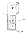
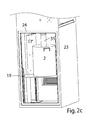
- FIG. 1 While in Fig. 1, the relative movement between the follower plate 4 and the container 2 by lowering the follower plate 4 by means of movement of the pressing pump 5 and suction tube 35 takes place, Fig. 2 show a solution in which, conversely, the follower plate 4 (in the Fig. 2 is not visible but within the container 2) and the associated pump 5 remain at rest and instead the container 2 against the feed direction 10 is moved upward by vertical movement of the base plate 19, on which the container 2, in turn inserted into a Container centering 36, is turned off.
- the base plate 19 is guided vertically along the vertical corner columns of the support frame 18 and movable by means of a lifting device 17 ', which acts on two on opposite sides of the base plate 19 Pneumatic cylinders 17b exists.
- a lifting device 17 ' which acts on two on opposite sides of the base plate 19 Pneumatic cylinders 17b exists.
- these are arranged in the corner regions of the quadrangular base plate 19 and protrude from the lower end position of the base plate 19 substantially from above, wherein the upwardly out of the cylinder 17b extendable piston rod 17a extending against a cylinder 17b above and presses the bridge 42 connected to the base plate 19.
- Wegmessvorraum 26 In addition to one of the lifting devices 17 'while a Wegmessvorraum 26 is arranged, which determines the altitude of the base plate 19 at any time.
- the application of force from the suction tube 35 is not directly on the follower plate 4, but through the intermediary of a stable, usually made of metal, pressure plate 41, which covers substantially the entire surface of the follower plate 4 from above, so that the follower plate 4th as disposable plastic and with relatively low intrinsic stability and thus can be made inexpensively.
- this emptying device 1 is accommodated in a closed, cabinet-like housing 23, whose front door 24, which is necessary for changing the container 2, has a viewing window for visually checking the correct emptying process.
- the housing 23, which is preferably produced by dense planking of the stability-securing support frame 18, on the one hand provides protection against engagement in the emptying device during operation, which would constitute a risk of injury from moving relative to each other parts, and on the other hand, the possibility therein for the paste to be handled correct physical parameters such.
- pressure, temperature and humidity in the interior of the container 23 to actively set and monitor which is particularly important in by atmospheric moisture and / or temperature-curing pastes, such as those used as sealants and adhesives, is of great importance.
- all functional parts of the emptying device in particular the control panel for the electrical control 25, are housed as well as all the sensors arranged for monitoring the emptying process, namely sensors for the aforementioned physical parameters of the atmosphere within the container 23 and a force sensor for the application of force to the container 2 and follower plate 4 against each other, and / or a pressure sensor for the pressure prevailing in the paste in the container 2 and / or in the suction tube 35 and the extraction line 34 Paste 20.
- the monitoring of the emptying process can be documented on the one hand and automatically monitored in addition to the manual optical control, which is mainly that above the follower plate 4 as well as at the passages between the follower plate, suction tube 35 and pump 5 etc. may escape.
- a peripheral edge 11 projects upwardly, the outer periphery of which widens conically upwards with a small skew angle of about 3 ° - 10 ° deviating from the vertical, wherein the material thickness of the rim 11 is to be measured the edge 11 with its freely leaking upper end elastically on the inner cross-section 3 of the container 2 can create tight.
- the screen plate 13 is stiffened by arranged on its top, star-shaped stiffening webs 15, which end at the same height as a circumferential shoulder 43 in the inner periphery of the rim 11 and the pump opening 12 surrounding annularly closed pumping wall 13 '.
- the webs 15 do not pass through in the radial direction, but instead have passages 44 between the regions separated from the webs 15, which have been omitted in the perspective illustration of FIG. 3c for reasons of simplified illustration ,
- the top plate 6 corresponds from its outer diameter to the inner diameter of the rim 11 at the height of the shoulder 43 and is closed except for a likewise existing, equally large central pump opening 12, of which in turn a pumping wall 13 projects upwards.
- FIGS. 5a and b Due to the tight connection of the preferably transparent top plate 6 with the sieve plate 7, the drum follower plate 4 or 4 'shown in FIG. 5 is produced in FIGS. 5a and b is shown in longitudinal section, and thereof the variant according to FIG. 5a as FIG. 5c in a three-dimensional view.
- the gap 8 'formed between the top plate 6 and the sieve plate 8 is only accessible to the distance 8' between the two plates via the at least one nozzle-shaped protruding from the top plate 6 vacuum connection 9.
- the pump opening 12 in Region of the pumping wall 13 also have an opening through a side open vacuum port 9 '.
- this gap 8 fills completely with paste 20, since as well as the screen openings 14 and the passages 44 in the webs 15 are dimensioned sufficiently large to pass through the paste 20 at the applied negative pressure.
- paste 20 will also emerge from the vacuum connection 9 towards a viewing tube 29 connected to it, which preferably is transparent like the top plate 6 and is used together with the follower plate 4 as a disposable part.
- sieve plate 7 and top plate 6 can be flat and thus also the underside 7 a of the sieve plate 7 represent a flat surface.
- Fig. 5b shows a design in which on the one hand the sieve plate 7 and thus also its bottom 7a slightly conically increases from the outer edge to the center, preferably at an angle of 5 ° - 15 °. As a result, the displacement of the paste 20 in the container 2 to the central pump opening 12 is supported.
- the distance 8 'between the top plate 6 and the sieve plate 7 can not be constant, but increase in one direction, for example, again from the outer edge to the central pumping wall 13 or vice versa, and the negative pressure port 9 thereby in the region of largest distance 8 'are arranged.
- Fig. 5 in the left half of the picture also show the application of the follower plate 4 in the feed direction 10 by the suction tube 35 by means of a pressure plate 41, which -. formed as a turned part and made of metal, in particular aluminum - covers substantially the entire top of the follower plate 4 and applied, so that the follower plate 4 can be made even with a lower intrinsic stability.
- a pressure plate 41 which -. formed as a turned part and made of metal, in particular aluminum - covers substantially the entire top of the follower plate 4 and applied, so that the follower plate 4 can be made even with a lower intrinsic stability.
- the pressure plate 41 is preferably connected via a thread 45 fixed to the suction tube 35.
- Fig. 5a also shows the when using a scoop pump as a pump 5 within the pump opening 12 up and down moving scoop piston 27, in a parking position 28, in which the standstill of the pump generally stops.
- the scoop piston 27 is designed so that it - at least in its parked position 28 - under certain circumstances rests tightly against the inner circumference of the pumping wall 13, also mediated by the piston 27 adhering paste 20 - so is preferably also in the pumping wall 13, namely at a location above the scooping piston 27 located in the parking position 28, a negative pressure connection 9 'provided in order to also be able to remove existing air at the beginning of the emptying process.
- the vacuum ports 9, 9 ' can be connected via a y-shaped viewing tube of sufficient length with one and the same vacuum source. Sufficient length of sight tubes is necessary to prevent that in one branch of the view tube no paste 20 is visible, while the other branch is so far filled with paste 20 that it threatens to pollute the behind the sight tube 29 following solid vacuum connection.
Landscapes
- Engineering & Computer Science (AREA)
- Mechanical Engineering (AREA)
- General Engineering & Computer Science (AREA)
- Basic Packing Technique (AREA)
- Mixers With Rotating Receptacles And Mixers With Vibration Mechanisms (AREA)
- Control And Other Processes For Unpacking Of Materials (AREA)
- Filling Or Emptying Of Bunkers, Hoppers, And Tanks (AREA)
- Feeding, Discharge, Calcimining, Fusing, And Gas-Generation Devices (AREA)
Applications Claiming Priority (2)
| Application Number | Priority Date | Filing Date | Title |
|---|---|---|---|
| DE102005039359 | 2005-08-19 | ||
| DE102005049805A DE102005049805B4 (de) | 2005-08-19 | 2005-10-18 | Entleervorrichtung |
Publications (3)
| Publication Number | Publication Date |
|---|---|
| EP1754543A2 true EP1754543A2 (fr) | 2007-02-21 |
| EP1754543A3 EP1754543A3 (fr) | 2007-06-20 |
| EP1754543B1 EP1754543B1 (fr) | 2008-12-10 |
Family
ID=37499525
Family Applications (1)
| Application Number | Title | Priority Date | Filing Date |
|---|---|---|---|
| EP06119157A Active EP1754543B1 (fr) | 2005-08-19 | 2006-08-18 | Appareil et méthode pour vider des conteneurs de substances visqueuses |
Country Status (4)
| Country | Link |
|---|---|
| US (1) | US7762428B2 (fr) |
| EP (1) | EP1754543B1 (fr) |
| AT (1) | ATE416851T1 (fr) |
| DE (2) | DE102005049805B4 (fr) |
Cited By (7)
| Publication number | Priority date | Publication date | Assignee | Title |
|---|---|---|---|---|
| WO2014056011A3 (fr) * | 2012-10-10 | 2014-07-17 | Waizenauer Dietmar | Dispositif mélangeur |
| DE202016005098U1 (de) | 2016-08-23 | 2016-08-31 | TÜNKERS-NICKEL Dosiersysteme GmbH | Pumpeinrichtung |
| DE202017005796U1 (de) | 2017-11-08 | 2017-11-27 | TÜNKERS-NICKEL Dosiersysteme GmbH | Folgeplatte mit Gasverteilung |
| DE102017215706A1 (de) | 2017-09-06 | 2019-03-07 | TÜNKERS-NICKEL Dosiersysteme GmbH | Verfahren zum automatisierten Anheben einer Fass-Folgeplatte und Pumpeinrichtung |
| CN114735640A (zh) * | 2022-04-13 | 2022-07-12 | 岚图汽车科技有限公司 | 一种能够自动锁紧胶桶的压胶设备 |
| US20220341541A1 (en) * | 2021-04-26 | 2022-10-27 | Danhydra A/S | Supply system comprising container for fluid and pump |
| EP4530247A1 (fr) * | 2023-09-26 | 2025-04-02 | Wagner International Ag | Dispositif avec plaque d'essuyage pour un récipient de stockage de matériau et appareil de déchargement avec ledit dispositif |
Families Citing this family (34)
| Publication number | Priority date | Publication date | Assignee | Title |
|---|---|---|---|---|
| DE102007003972B4 (de) * | 2007-01-26 | 2012-01-19 | Viscotec Pumpen- Und Dosiertechnik Gmbh | Vorrichtung zur luftfreien Entnahme und verbesserten Entlüftung mit porösen Trennplatten |
| CN101285696B (zh) * | 2007-04-11 | 2011-03-23 | 深圳迈瑞生物医疗电子股份有限公司 | 一种体积计量方法 |
| JP5196220B2 (ja) * | 2007-04-23 | 2013-05-15 | 兵神装備株式会社 | 汲出し装置 |
| US7459074B1 (en) * | 2007-07-27 | 2008-12-02 | Sanchez Robert M | Waste water filtering system |
| US7438820B1 (en) | 2007-07-27 | 2008-10-21 | Sanchez Robert M | Waste water filtering method and system |
| DE102008022859A1 (de) * | 2008-05-08 | 2009-11-12 | Dr. Ing. H.C. F. Porsche Aktiengesellschaft | Verfahren zur Abgabe eines fliessfähigen Füllgutes |
| DE102013005965A1 (de) * | 2013-04-09 | 2014-10-09 | Udo Tartler | Vorrichtung zum Abdichten und Evakuieren eines Behälters mit insbesondere pastöser Flüssigkeit |
| DE102013103734B4 (de) * | 2013-04-15 | 2014-11-13 | Walther Systemtechnik Gmbh | Fasspumpe |
| DE102014011395B4 (de) * | 2014-07-17 | 2025-09-18 | Atlas Copco Ias Gmbh | Vorrichtung zum Fördern von viskosem Material und Verfahren zum Wechseln eines Behälters |
| DE102016002263A1 (de) | 2016-02-25 | 2017-08-31 | Pressol - Schmiergeräte GmbH | Fördervorrichtung zur Förderung eines fließfähigen Mediums |
| DE102017100712A1 (de) * | 2017-01-16 | 2018-07-19 | Atlas Copco Ias Gmbh | Vorrichtung und Verfahren zum Fördern von viskosem Material |
| CN109641735B (zh) | 2016-09-05 | 2021-04-30 | 阿特拉斯柯普科工业技术(德国)有限公司 | 具有跟随板的可调节的密封环的桶式泵 |
| DE102016125207A1 (de) | 2016-12-21 | 2018-06-21 | Atlas Copco Ias Gmbh | Vorrichtung zum Fördern von viskosem Material |
| JP6760864B2 (ja) * | 2017-02-06 | 2020-09-23 | トヨタ自動車株式会社 | 吐出装置の真空引き構造及び真空引き方法 |
| CN110267745B (zh) * | 2017-02-28 | 2022-02-15 | 三键有限公司 | 粘性材料供给装置及供给方法、包覆片及其安装方法 |
| US11001492B2 (en) * | 2017-04-11 | 2021-05-11 | Udo Tartler | Device for sealing and evacuating a container containing a paste-like liquid |
| DE102017108187B4 (de) * | 2017-04-18 | 2019-02-28 | Scheugenpflug Ag | Entleervorrichtung für viskose Stoffe sowie Verfahren hierfür |
| DE102018000011B3 (de) | 2018-01-04 | 2019-02-07 | Hedrich Gmbh | Verfahren und Vorrichtung zur Entgasung eines mit Flüssigkeit oder Paste gefüllten Behälters mit Folgeplatte |
| DE102018104763A1 (de) | 2018-03-02 | 2019-09-05 | Atlas Copco Ias Gmbh | Verfahren zum Entfernen einer Folgeplatte aus einem Behälter |
| US10518988B1 (en) | 2018-08-27 | 2019-12-31 | Integrated Dispense Solutions | Safety mechanism for use with a drum unloader |
| DE102019126141A1 (de) * | 2019-09-27 | 2021-04-01 | Scheugenpflug Ag | Fassfolgeplatte |
| JP7351760B2 (ja) * | 2020-02-03 | 2023-09-27 | トヨタ自動車株式会社 | 流体圧送装置 |
| CN111392679A (zh) * | 2020-04-27 | 2020-07-10 | 信易电热机械有限公司 | 一种气动装换桶装置 |
| DE102020131081B3 (de) | 2020-11-24 | 2021-11-11 | ventUP GmbH | Verfahren zum Entleeren von viskosem Material aus einer beidseitig offenen Kartusche sowie hierfür geeignete Entleer-Vorrichtung |
| EP4331732A4 (fr) * | 2021-04-28 | 2025-07-30 | Tokyo Electron Ltd | Récipient |
| CN115898897A (zh) * | 2022-10-26 | 2023-04-04 | 西安热工研究院有限公司 | 一种熔盐泵装置及运行方法 |
| DE102022135039A1 (de) | 2022-12-30 | 2024-07-11 | Dosmatix Gmbh | Fassfolgeeinrichtung für eine Fassentleervorrichtung und Fassentleervorrichtung |
| DE102022135037A1 (de) | 2022-12-30 | 2024-07-11 | Dosmatix Gmbh | Schutzkappe, Fassfolgeplatte und Fassentleervorrichtung |
| DE202022002786U1 (de) | 2022-12-30 | 2023-06-23 | Dosmatix Gmbh | Schutzkappe, Fassfolgeplatte und Fassentleervorrichtung |
| EP4431737A1 (fr) | 2023-03-13 | 2024-09-18 | BETA Beratungs- und Beteiligungs-GmbH | Dispositif, procédé et élément de séparation pour ce procédé et pour prélever un milieu pompable d'un récipient |
| CN117841347B (zh) * | 2024-02-26 | 2024-09-10 | 江苏艾斯瑞特机械有限公司 | 一种用于塑料膜生产的吹膜设备 |
| DE102024127626A1 (de) | 2024-09-24 | 2026-03-26 | Atlas Copco Ias Gmbh | Vorrichtung zum Fördern eines viskosen Materials aus einem Behälter |
| CN119869819B (zh) * | 2025-02-19 | 2025-10-31 | 山东大学 | 一种银纳米线喷涂设备及喷涂方法 |
| DE102025117053B3 (de) | 2025-05-05 | 2026-03-12 | Dosmatix Gmbh | Fassfolgepumpe und Fassentleervorrichtung |
Family Cites Families (17)
| Publication number | Priority date | Publication date | Assignee | Title |
|---|---|---|---|---|
| US1936857A (en) * | 1933-02-09 | 1933-11-28 | Edward J Reisdorf | Coffee protector |
| US2221763A (en) * | 1937-07-10 | 1940-11-19 | Aro Equipment Corp | Pumping apparatus for grease and the like |
| US2280708A (en) * | 1940-11-04 | 1942-04-21 | Lincoln Eng Co | Pump |
| US2385579A (en) * | 1944-08-14 | 1945-09-25 | King Irving | Frozen confection dispenser |
| US2630248A (en) * | 1948-10-08 | 1953-03-03 | Dirkes Ind Inc | Pump for dispensing fluid substances from containers |
| US3412903A (en) * | 1967-06-20 | 1968-11-26 | Parkway Products Inc | Apparatus for heating and dispensing viscous materials |
| US3982669A (en) * | 1975-11-20 | 1976-09-28 | Industrial Machine Service Company | Hot melt dispensing apparatus and method |
| FR2544699B1 (fr) * | 1983-04-21 | 1987-05-07 | Fraco Sa | Dispositif pour vider des recipients contenant des produits thermofusibles |
| FR2550777B1 (fr) * | 1983-08-17 | 1985-12-06 | Fraco Sa | Dispositif pour vider des recipients contenant des produits de viscosite elevee |
| US4630760A (en) * | 1984-03-29 | 1986-12-23 | Johnstone Pump Company | Magnadrum pump assembly |
| US4635820A (en) * | 1986-01-09 | 1987-01-13 | Slautterback Corporation | Bulk unloader of solidified thermoplastic material from pails and drums |
| NL8701165A (nl) * | 1987-05-14 | 1988-12-01 | Langen Research | Inrichting voor het ledigen van een vat. |
| US5248069A (en) * | 1992-05-29 | 1993-09-28 | International Business Machines Corporation | Viscous fluid pressurizing apparatus |
| US5257723A (en) * | 1992-06-02 | 1993-11-02 | Nordson Corporation | Bulk melter with material recirculation |
| FR2742138A1 (fr) * | 1995-12-07 | 1997-06-13 | Bacardi Martini | Distributeur de liquide |
| US6056153A (en) * | 1998-09-08 | 2000-05-02 | Inoue Mfg., Inc. | Method and apparatus for extruding a highly viscous fluid from a tank |
| JP3297661B2 (ja) * | 2000-02-02 | 2002-07-02 | 株式会社ヤマダコーポレーション | 高粘度流体圧送用ポンプ装置 |
-
2005
- 2005-10-18 DE DE102005049805A patent/DE102005049805B4/de not_active Expired - Fee Related
-
2006
- 2006-08-17 US US11/506,032 patent/US7762428B2/en active Active
- 2006-08-18 AT AT06119157T patent/ATE416851T1/de not_active IP Right Cessation
- 2006-08-18 DE DE502006002309T patent/DE502006002309D1/de active Active
- 2006-08-18 EP EP06119157A patent/EP1754543B1/fr active Active
Cited By (9)
| Publication number | Priority date | Publication date | Assignee | Title |
|---|---|---|---|---|
| WO2014056011A3 (fr) * | 2012-10-10 | 2014-07-17 | Waizenauer Dietmar | Dispositif mélangeur |
| DE202016005098U1 (de) | 2016-08-23 | 2016-08-31 | TÜNKERS-NICKEL Dosiersysteme GmbH | Pumpeinrichtung |
| DE102017215706A1 (de) | 2017-09-06 | 2019-03-07 | TÜNKERS-NICKEL Dosiersysteme GmbH | Verfahren zum automatisierten Anheben einer Fass-Folgeplatte und Pumpeinrichtung |
| DE102017215706B4 (de) * | 2017-09-06 | 2021-06-10 | TÜNKERS-NICKEL Dosiersysteme GmbH | Verfahren zum automatisierten Anheben einer Fass-Folgeplatte und Pumpeinrichtung |
| DE202017005796U1 (de) | 2017-11-08 | 2017-11-27 | TÜNKERS-NICKEL Dosiersysteme GmbH | Folgeplatte mit Gasverteilung |
| US20220341541A1 (en) * | 2021-04-26 | 2022-10-27 | Danhydra A/S | Supply system comprising container for fluid and pump |
| US12123549B2 (en) * | 2021-04-26 | 2024-10-22 | Danhydra A/S | Supply system comprising container for fluid and pump |
| CN114735640A (zh) * | 2022-04-13 | 2022-07-12 | 岚图汽车科技有限公司 | 一种能够自动锁紧胶桶的压胶设备 |
| EP4530247A1 (fr) * | 2023-09-26 | 2025-04-02 | Wagner International Ag | Dispositif avec plaque d'essuyage pour un récipient de stockage de matériau et appareil de déchargement avec ledit dispositif |
Also Published As
| Publication number | Publication date |
|---|---|
| US7762428B2 (en) | 2010-07-27 |
| DE502006002309D1 (de) | 2009-01-22 |
| EP1754543A3 (fr) | 2007-06-20 |
| US20070039978A1 (en) | 2007-02-22 |
| DE102005049805B4 (de) | 2007-06-14 |
| DE102005049805A1 (de) | 2007-02-22 |
| EP1754543B1 (fr) | 2008-12-10 |
| ATE416851T1 (de) | 2008-12-15 |
Similar Documents
| Publication | Publication Date | Title |
|---|---|---|
| EP1754543B1 (fr) | Appareil et méthode pour vider des conteneurs de substances visqueuses | |
| EP3440010B1 (fr) | Dispositif de vidange de substances visqueuses et procédé associé | |
| DE102014114374B3 (de) | Entleervorrichtung mit einer Fasspresse sowie Verfahren zum Entleeren von viskosem Material | |
| AT512536B1 (de) | Mischvorrichtung | |
| EP3568375B1 (fr) | Procédé et dispositif de refoulement de matière visqueuse | |
| EP3325174B1 (fr) | Dispositif de transport de matériau visqueux | |
| DE102004030654A1 (de) | Vorrichtung zum Fördern von viskosem Material | |
| EP2085614A1 (fr) | Dispositif de pompage, en particulier pompe à double membrane avec entrainement par pompe à piston | |
| DE102007041666B4 (de) | Vorrichtung und Verfahren zum Mischen von Knochenzement | |
| EP3507236B1 (fr) | Pompe électrique portative à bague d'étanchéité adaptable de la plaque suiveuse | |
| EP3296075B1 (fr) | Dispositif de transport d'une matière visqueuse provenant d'un récipient et procédé de fonctionnement du dispositif de transport | |
| WO2018167205A1 (fr) | Dispositif destiné à faire le vide dans un récipient contenant un liquide pâteux | |
| DE19713938C2 (de) | Abgabevorrichtung und Abgabeverfahren für ein hochviskoses Material mit konstanter Ausströmrate | |
| DE102021109816A1 (de) | Verfahren zum Entleeren von viskosem Material aus einer beidseitig offenen Kartusche sowie hierfür geeignete Entleer-Vorrichtung | |
| EP4530247B1 (fr) | Dispositif avec plaque d'essuyage pour un récipient de stockage de matériau et appareil de déchargement avec ledit dispositif | |
| EP4251879A1 (fr) | Procédé pour vider un matériau visqueux d'une cartouche ouverte des deux côtés, et dispositif de vidage conçu à cet effet | |
| DE4416089A1 (de) | Anordnung zum Dispensieren von hochviskosen Flüssigkeiten | |
| DE19914499A1 (de) | Fördervorrichtung für pastöse Massen und Verfahren zur Bestimmung deren Luftinhaltes | |
| EP0150292B1 (fr) | Dispositif pour le remplissage dosé d'un matériau très visqueux | |
| DE202017101507U1 (de) | Vorrichtung zum Evakuieren eines Behälters mit pastöser Flüssigkeit | |
| DE102005006542A1 (de) | Vorrichtung und Verfahren zum Verflüssigen und Fördern von einem in einem Fass enthaltenen, verflüssigbaren thermoplastischen Material | |
| DE102025117053B3 (de) | Fassfolgepumpe und Fassentleervorrichtung | |
| DE69728129T4 (de) | Entlüftungsvorrichtung und -verfahren für visköse oder dickflüssige Substanzen | |
| EP3610179A1 (fr) | Dispositif destiné à étanchéifier et à faire le vide dans un récipient contenant un liquide pâteux | |
| DE102015000410A1 (de) | System zum Pumpen hochviskoser und stichfester Massen aus Behältern |
Legal Events
| Date | Code | Title | Description |
|---|---|---|---|
| PUAI | Public reference made under article 153(3) epc to a published international application that has entered the european phase |
Free format text: ORIGINAL CODE: 0009012 |
|
| AK | Designated contracting states |
Kind code of ref document: A2 Designated state(s): AT BE BG CH CY CZ DE DK EE ES FI FR GB GR HU IE IS IT LI LT LU LV MC NL PL PT RO SE SI SK TR |
|
| AX | Request for extension of the european patent |
Extension state: AL BA HR MK YU |
|
| PUAL | Search report despatched |
Free format text: ORIGINAL CODE: 0009013 |
|
| AK | Designated contracting states |
Kind code of ref document: A3 Designated state(s): AT BE BG CH CY CZ DE DK EE ES FI FR GB GR HU IE IS IT LI LT LU LV MC NL PL PT RO SE SI SK TR |
|
| AX | Request for extension of the european patent |
Extension state: AL BA HR MK YU |
|
| RIC1 | Information provided on ipc code assigned before grant |
Ipc: B05C 11/10 20060101AFI20061229BHEP Ipc: F04B 23/02 20060101ALI20070511BHEP Ipc: B29B 13/02 20060101ALI20070511BHEP Ipc: F04C 13/00 20060101ALI20070511BHEP |
|
| 17P | Request for examination filed |
Effective date: 20071113 |
|
| 17Q | First examination report despatched |
Effective date: 20071221 |
|
| AKX | Designation fees paid |
Designated state(s): AT BE BG CH CY CZ DE DK EE ES FI FR GB GR HU IE IS IT LI LT LU LV MC NL PL PT RO SE SI SK TR |
|
| AXX | Extension fees paid |
Extension state: HR Payment date: 20071220 Extension state: BA Payment date: 20071220 Extension state: YU Payment date: 20071220 Extension state: MK Payment date: 20071220 Extension state: AL Payment date: 20071220 |
|
| RAX | Requested extension states of the european patent have changed |
Extension state: HR Payment date: 20071220 Extension state: AL Payment date: 20071220 Extension state: RS Payment date: 20071220 Extension state: BA Payment date: 20071220 Extension state: MK Payment date: 20071220 |
|
| GRAP | Despatch of communication of intention to grant a patent |
Free format text: ORIGINAL CODE: EPIDOSNIGR1 |
|
| GRAS | Grant fee paid |
Free format text: ORIGINAL CODE: EPIDOSNIGR3 |
|
| GRAA | (expected) grant |
Free format text: ORIGINAL CODE: 0009210 |
|
| AK | Designated contracting states |
Kind code of ref document: B1 Designated state(s): AT BE BG CH CY CZ DE DK EE ES FI FR GB GR HU IE IS IT LI LT LU LV MC NL PL PT RO SE SI SK TR |
|
| REG | Reference to a national code |
Ref country code: GB Ref legal event code: FG4D Free format text: NOT ENGLISH |
|
| REG | Reference to a national code |
Ref country code: CH Ref legal event code: EP |
|
| REG | Reference to a national code |
Ref country code: IE Ref legal event code: FG4D Free format text: LANGUAGE OF EP DOCUMENT: GERMAN |
|
| REF | Corresponds to: |
Ref document number: 502006002309 Country of ref document: DE Date of ref document: 20090122 Kind code of ref document: P |
|
| REG | Reference to a national code |
Ref country code: CH Ref legal event code: NV Representative=s name: SCHMAUDER & PARTNER AG PATENTANWALTSBUERO |
|
| PG25 | Lapsed in a contracting state [announced via postgrant information from national office to epo] |
Ref country code: LT Free format text: LAPSE BECAUSE OF FAILURE TO SUBMIT A TRANSLATION OF THE DESCRIPTION OR TO PAY THE FEE WITHIN THE PRESCRIBED TIME-LIMIT Effective date: 20081210 |
|
| PG25 | Lapsed in a contracting state [announced via postgrant information from national office to epo] |
Ref country code: LV Free format text: LAPSE BECAUSE OF FAILURE TO SUBMIT A TRANSLATION OF THE DESCRIPTION OR TO PAY THE FEE WITHIN THE PRESCRIBED TIME-LIMIT Effective date: 20081210 Ref country code: NL Free format text: LAPSE BECAUSE OF FAILURE TO SUBMIT A TRANSLATION OF THE DESCRIPTION OR TO PAY THE FEE WITHIN THE PRESCRIBED TIME-LIMIT Effective date: 20081210 Ref country code: PL Free format text: LAPSE BECAUSE OF FAILURE TO SUBMIT A TRANSLATION OF THE DESCRIPTION OR TO PAY THE FEE WITHIN THE PRESCRIBED TIME-LIMIT Effective date: 20081210 Ref country code: FI Free format text: LAPSE BECAUSE OF FAILURE TO SUBMIT A TRANSLATION OF THE DESCRIPTION OR TO PAY THE FEE WITHIN THE PRESCRIBED TIME-LIMIT Effective date: 20081210 Ref country code: SI Free format text: LAPSE BECAUSE OF FAILURE TO SUBMIT A TRANSLATION OF THE DESCRIPTION OR TO PAY THE FEE WITHIN THE PRESCRIBED TIME-LIMIT Effective date: 20081210 |
|
| NLV1 | Nl: lapsed or annulled due to failure to fulfill the requirements of art. 29p and 29m of the patents act | ||
| REG | Reference to a national code |
Ref country code: IE Ref legal event code: FD4D |
|
| PG25 | Lapsed in a contracting state [announced via postgrant information from national office to epo] |
Ref country code: IE Free format text: LAPSE BECAUSE OF FAILURE TO SUBMIT A TRANSLATION OF THE DESCRIPTION OR TO PAY THE FEE WITHIN THE PRESCRIBED TIME-LIMIT Effective date: 20081210 Ref country code: BG Free format text: LAPSE BECAUSE OF FAILURE TO SUBMIT A TRANSLATION OF THE DESCRIPTION OR TO PAY THE FEE WITHIN THE PRESCRIBED TIME-LIMIT Effective date: 20090310 Ref country code: EE Free format text: LAPSE BECAUSE OF FAILURE TO SUBMIT A TRANSLATION OF THE DESCRIPTION OR TO PAY THE FEE WITHIN THE PRESCRIBED TIME-LIMIT Effective date: 20081210 Ref country code: ES Free format text: LAPSE BECAUSE OF FAILURE TO SUBMIT A TRANSLATION OF THE DESCRIPTION OR TO PAY THE FEE WITHIN THE PRESCRIBED TIME-LIMIT Effective date: 20090321 Ref country code: RO Free format text: LAPSE BECAUSE OF FAILURE TO SUBMIT A TRANSLATION OF THE DESCRIPTION OR TO PAY THE FEE WITHIN THE PRESCRIBED TIME-LIMIT Effective date: 20081210 |
|
| REG | Reference to a national code |
Ref country code: CH Ref legal event code: PCAR Free format text: SCHMAUDER & PARTNER AG PATENT- UND MARKENANWAELTE VSP;ZWAENGIWEG 7;8038 ZUERICH (CH) |
|
| PG25 | Lapsed in a contracting state [announced via postgrant information from national office to epo] |
Ref country code: PT Free format text: LAPSE BECAUSE OF FAILURE TO SUBMIT A TRANSLATION OF THE DESCRIPTION OR TO PAY THE FEE WITHIN THE PRESCRIBED TIME-LIMIT Effective date: 20090511 Ref country code: SE Free format text: LAPSE BECAUSE OF FAILURE TO SUBMIT A TRANSLATION OF THE DESCRIPTION OR TO PAY THE FEE WITHIN THE PRESCRIBED TIME-LIMIT Effective date: 20090310 Ref country code: CZ Free format text: LAPSE BECAUSE OF FAILURE TO SUBMIT A TRANSLATION OF THE DESCRIPTION OR TO PAY THE FEE WITHIN THE PRESCRIBED TIME-LIMIT Effective date: 20081210 Ref country code: IS Free format text: LAPSE BECAUSE OF FAILURE TO SUBMIT A TRANSLATION OF THE DESCRIPTION OR TO PAY THE FEE WITHIN THE PRESCRIBED TIME-LIMIT Effective date: 20090410 |
|
| PG25 | Lapsed in a contracting state [announced via postgrant information from national office to epo] |
Ref country code: SK Free format text: LAPSE BECAUSE OF FAILURE TO SUBMIT A TRANSLATION OF THE DESCRIPTION OR TO PAY THE FEE WITHIN THE PRESCRIBED TIME-LIMIT Effective date: 20081210 |
|
| PLBE | No opposition filed within time limit |
Free format text: ORIGINAL CODE: 0009261 |
|
| STAA | Information on the status of an ep patent application or granted ep patent |
Free format text: STATUS: NO OPPOSITION FILED WITHIN TIME LIMIT |
|
| PG25 | Lapsed in a contracting state [announced via postgrant information from national office to epo] |
Ref country code: DK Free format text: LAPSE BECAUSE OF FAILURE TO SUBMIT A TRANSLATION OF THE DESCRIPTION OR TO PAY THE FEE WITHIN THE PRESCRIBED TIME-LIMIT Effective date: 20081210 |
|
| 26N | No opposition filed |
Effective date: 20090911 |
|
| BERE | Be: lapsed |
Owner name: SCHEUGENPFLUG, ERICH Effective date: 20090831 |
|
| PG25 | Lapsed in a contracting state [announced via postgrant information from national office to epo] |
Ref country code: MC Free format text: LAPSE BECAUSE OF NON-PAYMENT OF DUE FEES Effective date: 20090831 |
|
| PG25 | Lapsed in a contracting state [announced via postgrant information from national office to epo] |
Ref country code: BE Free format text: LAPSE BECAUSE OF NON-PAYMENT OF DUE FEES Effective date: 20090831 |
|
| PG25 | Lapsed in a contracting state [announced via postgrant information from national office to epo] |
Ref country code: GR Free format text: LAPSE BECAUSE OF FAILURE TO SUBMIT A TRANSLATION OF THE DESCRIPTION OR TO PAY THE FEE WITHIN THE PRESCRIBED TIME-LIMIT Effective date: 20090311 |
|
| PG25 | Lapsed in a contracting state [announced via postgrant information from national office to epo] |
Ref country code: AT Free format text: LAPSE BECAUSE OF NON-PAYMENT OF DUE FEES Effective date: 20090818 |
|
| PG25 | Lapsed in a contracting state [announced via postgrant information from national office to epo] |
Ref country code: IT Free format text: LAPSE BECAUSE OF FAILURE TO SUBMIT A TRANSLATION OF THE DESCRIPTION OR TO PAY THE FEE WITHIN THE PRESCRIBED TIME-LIMIT Effective date: 20081210 |
|
| PG25 | Lapsed in a contracting state [announced via postgrant information from national office to epo] |
Ref country code: LU Free format text: LAPSE BECAUSE OF NON-PAYMENT OF DUE FEES Effective date: 20090818 |
|
| PG25 | Lapsed in a contracting state [announced via postgrant information from national office to epo] |
Ref country code: HU Free format text: LAPSE BECAUSE OF FAILURE TO SUBMIT A TRANSLATION OF THE DESCRIPTION OR TO PAY THE FEE WITHIN THE PRESCRIBED TIME-LIMIT Effective date: 20090611 |
|
| PG25 | Lapsed in a contracting state [announced via postgrant information from national office to epo] |
Ref country code: TR Free format text: LAPSE BECAUSE OF FAILURE TO SUBMIT A TRANSLATION OF THE DESCRIPTION OR TO PAY THE FEE WITHIN THE PRESCRIBED TIME-LIMIT Effective date: 20081210 |
|
| PG25 | Lapsed in a contracting state [announced via postgrant information from national office to epo] |
Ref country code: CY Free format text: LAPSE BECAUSE OF FAILURE TO SUBMIT A TRANSLATION OF THE DESCRIPTION OR TO PAY THE FEE WITHIN THE PRESCRIBED TIME-LIMIT Effective date: 20081210 |
|
| PGFP | Annual fee paid to national office [announced via postgrant information from national office to epo] |
Ref country code: CH Payment date: 20110824 Year of fee payment: 6 |
|
| PGFP | Annual fee paid to national office [announced via postgrant information from national office to epo] |
Ref country code: GB Payment date: 20110824 Year of fee payment: 6 Ref country code: FR Payment date: 20110829 Year of fee payment: 6 |
|
| REG | Reference to a national code |
Ref country code: CH Ref legal event code: PL |
|
| GBPC | Gb: european patent ceased through non-payment of renewal fee |
Effective date: 20120818 |
|
| PG25 | Lapsed in a contracting state [announced via postgrant information from national office to epo] |
Ref country code: LI Free format text: LAPSE BECAUSE OF NON-PAYMENT OF DUE FEES Effective date: 20120831 Ref country code: CH Free format text: LAPSE BECAUSE OF NON-PAYMENT OF DUE FEES Effective date: 20120831 |
|
| REG | Reference to a national code |
Ref country code: FR Ref legal event code: ST Effective date: 20130430 |
|
| PG25 | Lapsed in a contracting state [announced via postgrant information from national office to epo] |
Ref country code: GB Free format text: LAPSE BECAUSE OF NON-PAYMENT OF DUE FEES Effective date: 20120818 |
|
| PG25 | Lapsed in a contracting state [announced via postgrant information from national office to epo] |
Ref country code: FR Free format text: LAPSE BECAUSE OF NON-PAYMENT OF DUE FEES Effective date: 20120831 |
|
| REG | Reference to a national code |
Ref country code: DE Ref legal event code: R082 Ref document number: 502006002309 Country of ref document: DE Representative=s name: PATENTANWAELTE WEICKMANN & WEICKMANN, DE Ref country code: DE Ref legal event code: R082 Ref document number: 502006002309 Country of ref document: DE Representative=s name: WEICKMANN & WEICKMANN PATENTANWAELTE - RECHTSA, DE Ref country code: DE Ref legal event code: R082 Ref document number: 502006002309 Country of ref document: DE Representative=s name: WEICKMANN & WEICKMANN PATENT- UND RECHTSANWAEL, DE |
|
| REG | Reference to a national code |
Ref country code: DE Ref legal event code: R082 Ref document number: 502006002309 Country of ref document: DE Representative=s name: WEICKMANN & WEICKMANN PATENT- UND RECHTSANWAEL, DE Ref country code: DE Ref legal event code: R081 Ref document number: 502006002309 Country of ref document: DE Owner name: SCHEUGENPFLUG AG, DE Free format text: FORMER OWNER: SCHEUGENPFLUG, ERICH, 93333 NEUSTADT, DE |
|
| P01 | Opt-out of the competence of the unified patent court (upc) registered |
Effective date: 20230526 |
|
| PGFP | Annual fee paid to national office [announced via postgrant information from national office to epo] |
Ref country code: DE Payment date: 20250728 Year of fee payment: 20 |