EP4530247A1 - Dispositif avec plaque d'essuyage pour un récipient de stockage de matériau et appareil de déchargement avec ledit dispositif - Google Patents
Dispositif avec plaque d'essuyage pour un récipient de stockage de matériau et appareil de déchargement avec ledit dispositif Download PDFInfo
- Publication number
- EP4530247A1 EP4530247A1 EP23199588.7A EP23199588A EP4530247A1 EP 4530247 A1 EP4530247 A1 EP 4530247A1 EP 23199588 A EP23199588 A EP 23199588A EP 4530247 A1 EP4530247 A1 EP 4530247A1
- Authority
- EP
- European Patent Office
- Prior art keywords
- container
- follower plate
- porous layer
- following device
- layer
- Prior art date
- Legal status (The legal status is an assumption and is not a legal conclusion. Google has not performed a legal analysis and makes no representation as to the accuracy of the status listed.)
- Granted
Links
Images


Classifications
-
- B—PERFORMING OPERATIONS; TRANSPORTING
- B67—OPENING, CLOSING OR CLEANING BOTTLES, JARS OR SIMILAR CONTAINERS; LIQUID HANDLING
- B67D—DISPENSING, DELIVERING OR TRANSFERRING LIQUIDS, NOT OTHERWISE PROVIDED FOR
- B67D7/00—Apparatus or devices for transferring liquids from bulk storage containers or reservoirs into vehicles or into portable containers, e.g. for retail sale purposes
- B67D7/06—Details or accessories
- B67D7/58—Arrangements of pumps
- B67D7/62—Arrangements of pumps power operated
- B67D7/64—Arrangements of pumps power operated of piston type
- B67D7/645—Barrel pumps
-
- F—MECHANICAL ENGINEERING; LIGHTING; HEATING; WEAPONS; BLASTING
- F04—POSITIVE - DISPLACEMENT MACHINES FOR LIQUIDS; PUMPS FOR LIQUIDS OR ELASTIC FLUIDS
- F04B—POSITIVE-DISPLACEMENT MACHINES FOR LIQUIDS; PUMPS
- F04B15/00—Pumps adapted to handle specific fluids, e.g. by selection of specific materials for pumps or pump parts
- F04B15/02—Pumps adapted to handle specific fluids, e.g. by selection of specific materials for pumps or pump parts the fluids being viscous or non-homogeneous
-
- F—MECHANICAL ENGINEERING; LIGHTING; HEATING; WEAPONS; BLASTING
- F04—POSITIVE - DISPLACEMENT MACHINES FOR LIQUIDS; PUMPS FOR LIQUIDS OR ELASTIC FLUIDS
- F04B—POSITIVE-DISPLACEMENT MACHINES FOR LIQUIDS; PUMPS
- F04B23/00—Pumping installations or systems
- F04B23/02—Pumping installations or systems having reservoirs
-
- F—MECHANICAL ENGINEERING; LIGHTING; HEATING; WEAPONS; BLASTING
- F04—POSITIVE - DISPLACEMENT MACHINES FOR LIQUIDS; PUMPS FOR LIQUIDS OR ELASTIC FLUIDS
- F04B—POSITIVE-DISPLACEMENT MACHINES FOR LIQUIDS; PUMPS
- F04B53/00—Component parts, details or accessories not provided for in, or of interest apart from, groups F04B1/00 - F04B23/00 or F04B39/00 - F04B47/00
- F04B53/06—Venting
Definitions
- the invention relates to a container following device for a material storage container and a conveying device with the container following device for conveying material from the material storage container.
- the container following device can be part of a conveying device, wherein the conveying device serves to convey viscous material out of the container.
- the conveying device can be used to reliably convey various medium- to high-viscosity materials, such as sealants, adhesives, or silicone rubber, from containers such as buckets or drums to various processing systems.
- the viscous material is typically provided by the material supplier in containers with a capacity of 20 l to 1000 l.
- the conveying device is also referred to as a feed system for transporting viscous materials.
- An object of the invention is to provide a container following device for a material storage container in which the follower plate of the container following device remains clean at all times.
- the container follower device according to the invention for a material storage container is designed such that it can be lowered into the material storage container.
- the container follower device comprises a material removal opening for removing material from the material storage container and an outlet opening for discharging gas from the material storage container.
- the container follower device comprises a follower plate, a porous layer arranged below the follower plate, and an air-impermeable separating layer. The separating layer is arranged at least partially between the follower plate and the porous layer and surrounds the material removal opening.
- the separating layer is a coating, a silicone layer, a film, a sheet or a plastic plate.
- the separating layer is adhesive on one side.
- the separating layer is resistant to the material to be conveyed.
- the separation layer is attached to the porous layer with an adhesive, it can be advantageous if the adhesive used is also resistant to the material being conveyed. It is also advantageous if an adhesive is used to attach the separation layer to the porous layer that does not impair the quality of the material being conveyed.
- a separating plate is provided, which is arranged at least partially between the follower plate and the porous layer.
- the separating plate can be provided with an adhesive layer to enable the porous layer to be attached to the separating plate.
- the separating plate has one or more openings which form a channel which is connected to the outlet opening.
- a seal is provided to seal the follower plate from the container.
- the seal is held between the separating plate and the follower plate.
- the seal can also be arranged in a groove of the follower plate.
- the porous layer is designed as a seal. This allows the gap between the follower plate and the inside of the material storage container to be easily bridged and sealed.
- a material conveyor is provided which projects into the material removal opening.
- the porous layer comprises aluminum foam, metal foam, ceramic foam, plastic foam or foam.
- the porous layer is an open-cell layer, so that it is permeable to air or gas.
- the porous layer has a pore width in the range of 5 ppi to 250 ppi.
- the porous layer comprises sintered material.
- the porous layer has a thickness in the range from 10 mm to 100 mm.
- the separating plate may have one or more openings.
- the openings are configured to form a channel that is connected to the outlet opening.
- the mouth of the channel is at least 10 mm away from the material removal opening.
- the channel at least partially surrounds the material removal opening.
- the channel serves to guide the air to the outlet opening.
- the channel is formed in a ring shape around the material removal opening.
- the channel can, for example, have a circular, rectangular, or polygonal shape.
- the separating layer is arranged between the material removal opening and the mouth of the channel.
- the porous layer is arranged in such a way that it is not in contact with the follower plate, at least in the region of the separating layer.
- the porous layer preferably has an outer diameter selected so that the porous layer centers itself in the material storage container.
- a conveying device for conveying material from a material storage container which comprises the container following device described above. Furthermore, it has a material conveyor configured to convey the material through the container following device.
- a method for operating the conveying device described above comprising the following steps: The porous layer is placed in the material storage container. In a further step, the follower plate is lowered onto the porous layer. In an additional step, the gas still present in the material storage container is discharged from the material storage container via the outlet opening.
- the follower plate is lifted out of the material storage container without the porous layer.
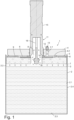
- FIG 1 A first possible embodiment of a container follower 1 for a material storage container 2 is shown in section.
- the container follower 1 is usually part of a conveying device 20, with which viscous material 3 can be conveyed out of the material storage container 2.
- a possible embodiment of such a conveying device 20 is shown in the Figures 8 to 17 shown.
- various medium to high viscosity materials such as sealants, adhesives, silicone rubber or greases, can be reliably conveyed from the material storage container 2 to various processing systems.
- the conveying device 20 comprises a material conveyor 11.
- the material conveyor 11 can be, for example, a pump.
- the pump 11 comprises a drive 14, a drive rod 18 connected thereto, and a pump body 15.
- the pump 11 is driven via the drive 14 and the drive rod 18.
- the drive 14 is configured such that it causes the drive rod 18 with scooping piston 19 to perform a lifting movement, which is transmitted to the scooping piston 19 of the pump 11.
- the pump 11 can also be a piston pump without a scooping piston.
- the scooping piston has the advantage with highly viscous materials that the viscous material is scooped directly to the material discharge opening 8.
- the material discharge opening 8 is also referred to below as the pump inlet. This can improve the suction behavior of the pump. If, however, the pump 11 is designed as a gear pump, spindle pump, or eccentric screw pump, the drive is designed to set the drive rod 18 in a rotational motion, which is transmitted to the gear pump, the spindle pump, or the eccentric screw pump, respectively.
- the pump 11 is designed as a scoop piston pump.
- Figure 1 shows the basic design of such a scoop piston pump.
- a follower plate 4 Located below the pump 11 is a follower plate 4, which can be inserted into the material storage container 2 containing the material 3 to be pumped.
- the material storage container 2 is also referred to below as the storage container or container.
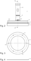
- the follower plate 4 is preferably equipped with an annular seal 5 so that the follower plate 4 can form a sealing contact with the inner side 2.1 of the container wall 2.4.
- the seal 5 can be, for example, an O-ring or a sealing lip. It ensures, among other things, that no material 3 escapes between the follower plate 4 and the container wall 2.4.
- the seal 5 also enables the effective build-up of a negative pressure in the container interior 2.2.
- One possible embodiment of the seal 5 is shown in the Figures 3 and 4 In this embodiment, the seal 5 is annular.
- the outer diameter of the seal 5 and the inner diameter of the container 2 are coordinated.
- the outer diameter of the seal 5 can be 288 mm, for example. In principle, the seal 5 should be larger than the inner diameter of the container 2.
- a suitable container 2 has a diameter of 292 mm if the seal is designed as an O-ring. If the seal 5 is designed as a sealing lip, it can seal a sealing gap of, for example, 0 to 20 mm.
- the invention is also suitable for a 200-liter material storage container (inner diameter approx. 570 mm). Of course, the invention can also be used for even larger material storage containers.
- the seal 5 can be arranged between the follower plate 4 and the separating plate 6.
- the follower plate 4 can also have a groove 4.2 in which the seal 5 is arranged.
- Figure 2 the groove 4.2 is indicated by a dashed line.
- the follower plate 4 has a pressure-effective surface 4.2, which can be at least partially inclined. This can partially increase the pressure on the material 3 to be conveyed and ensure that the material 3 flows more strongly to the material removal opening 8.
- the pump 11 can convey the viscous material 3 out of the container 2 through the material removal opening 8.
- the scoop piston pump has a scoop piston for this purpose, with a scoop piston plate 19 located at its lower end. In order to scoop the material 3 out of the container 2 convey, the drive rod 18 is moved downwards so that the scooping piston plate 19 dips into the material 3 and takes up material. During the upward movement of the drive rod 18, the scooping piston plate 19 takes the material 3 through the material removal opening 8 into the interior of the pump 11.
- the container follower 1 is designed to be lowerable into the material storage container 2. This allows the level of the container follower 1 to adapt to the changing material level.
- the pump 11 can convey the material 3 through the container follower 1 out of the storage container 2 via the material removal opening 8.
- the container follower device 1 comprises a channel 9 and an outlet opening 13 connected to the channel 9 for discharging gas from the material storage container 2.
- the gas is typically air.
- a connection 12 with an opening forming the outlet opening 13 can be provided on the follower plate 4.
- the channel 9 extends through the follower plate 4.
- the through opening 4.1 provided for this purpose in the follower plate 4 is part of the channel 9.
- the separating layer 10 is arranged at least partially between the follower plate 4 and the porous layer 7 and surrounds the material removal opening 8.
- the separating layer 10 can be, for example, a film, a sheet, or a plastic plate.
- the separating layer 10 can also be a coating, such as a lacquer layer. It can also be a silicone layer. If an adhesive layer is present, this can also serve as a separating layer.
- the separating layer 10 can also be a layer impregnated with a liquid.
- a liquid is used that hardens or crosslinks within the layer, creating a gas-impermeable separating layer 10.
- the porous layer 7 has a multitude of pores.
- a pore is defined here as a very small opening in the layer 7 that is permeable to gas.
- the number of pores per length of the porous layer 7 is preferably between 5 ppi and 250 ppi (pores per inch).
- the porous layer 7 can, for example, comprise sintered material.
- the porous layer 7 can also be produced using a 3D printing process.
- the porous layer 7 is preferably designed in such a way that it remains permeable to air even during evacuation, i.e. when the air is sucked out of the container interior 2.2.
- the inlet-side opening of the channel 9 is preferably at least 10 mm and better still 20 mm away from the material removal opening 8.
- a separating plate 6 can be arranged between the porous layer 7 and the seal 5.
- the separating plate 6 serves as additional support between the seal 5 and the porous layer 7. It also ensures a more homogeneous force distribution.
- the separating plate 6 can have air extraction openings 9. The air can be extracted from the container 2 through the air extraction openings 9. The air flows from below through the porous layer 7, the air extraction openings 9, the through-opening 4.1, and the outlet opening 13 to the outside.
- the follower plate 4 is arranged on the drive rod 15 of the pump 11.
- the follower plate 4 has the connection 12 on its upper side, which can be used, for example, for venting.
- the seal 5 is arranged on the underside of the follower plate 4.
- the seal 5 preferably has a larger Diameter than the follower plate 4. This has the advantage that the sealing effect is increased and, for example, material 3 adhering to the container wall 2.4 is scraped downwards by the seal 5 when the follower plate 4 is lowered into the container 2. This reduces material loss.
- the seal 5 it is also conceivable for the seal 5 to have the same diameter as the follower plate 4.
- the seal 5 is annular.
- the seal 5 can be connected to the follower plate 4.
- the seal 5 can have bores 5.1 for receiving screws (not shown) with which it is screwed to the follower plate 4.
- the Figures 5 - 7 show the porous layer 7 with the separating layer 10 arranged on it.
- the coloring of the Figure 5 is merely for better comprehensibility.
- the separation layer 10 has a smaller diameter than the porous layer 7.
- the ratio of the diameters between the porous layer 7 and the separation layer 10 shown here is also merely for illustrative purposes.
- the diameter of the separation layer 10 can, for example, be approximately as large as that of the porous layer 7. However, the diameter of the separation layer 10 can also be significantly smaller than, for example, in Figure 5
- the diameter of the separation layer 10 depends on the size of the container 2 used.
- the separation layer 10 preferably covers between 10% and 90% of the porous layer 7.
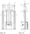
- the conveyor device 20 is, according to the Figures 8 to 17 This is an exemplary embodiment.
- the drive 14 is attached to a motor mount 28.
- the motor mount 28 is attached to a yoke 21 by means of a first rod 23 and a second rod 25.
- the two rods 23 and 25 can be designed as tubes and hold and stabilize the two lifting rods 24 and 26.
- the follower plate 4 is located at the lower end of the two lifting rods 24 and 26.
- the yoke 21 is supported by two lifting cylinders 31.
- the lifting cylinders 31, the yoke 21, the rods 23, 24, and the lifting rods 25 and 26 form a pump jack, which serves to raise and lower the drive 14, the pump 11, and the follower plate 4.
- the lifting cylinders 31 are typically pressurized, allowing the follower plate 4 to automatically follow the material level.
- the porous layer 7 is directly or indirectly connected to the follower plate 4. In this case, the porous layer 7 moves together with the follower plate 7. Alternatively, it can also be provided that the porous layer 7 is not connected to the follower plate 4. The porous layer 7 is therefore loosely placed on the material surface. If the follower plate 7 is raised, the position of the porous layer 7 does not change. However, if the follower plate 7 is lowered, the porous layer 7 is inevitably lowered as well, because the follower plate 7 presses on the porous layer 7 from above and thus carries it along.
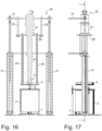
- the container follower 1 is first pulled out of the container 2. Subsequently, the container 2 is removed from the conveyor device 20. Then a full container 2 is pushed into the conveyor device 20 and positioned under the follower plate 4. The container follower 1 is located in the Figures 8 and 9 shown position, i.e. above container 2.
- the pump drive 14, the pump 11, and the container follower device 1 are lowered with the aid of the pump jack until the porous layer 7 in the container 2 rests on the material 3 to be conveyed. In this case, it may happen that air becomes trapped between the surface of the material 3 to be conveyed, the container wall 2.4, and the porous layer 7. This is the case regardless of whether the porous layer 7 is connected to the follower plate 4 or not.
- porous layer 7 can also be first placed into the container 2 and then the follower plate 4 can be lowered onto the porous layer 7. In the latter procedure, the porous layer 7 is preferably placed manually into the container 2 and lowered down to the material 3 if necessary.
- the follower plate 4 and the porous layer 7 can be allowed to rest on the material 3 to be conveyed for a certain period of time in a first venting phase to allow the material 2 time to spread.
- the duration (rest period) can be adjusted, for example, to the viscosity of the material.
- the first venting phase is optional.
- the vent valve on the container follower 1 is opened so that the air located under the porous layer 7 can pass through the porous layer 7 and then escape through the channel 9 and the outlet opening 13.
- the flow path of the air is indicated by arrows (see Figure 1 ).
- the air is directed through the porous layer 7, which covers the material surface up to the container edge.
- the air can also flow between the separating layer 10 and the separating plate 6.
- the vent valve is then closed again. This procedure is advantageous but not absolutely necessary.
- the porous layer 7 can be pressed onto the material 3 by means of the follower plate 4.
- the air can also be additionally sucked out via the outlet opening 13.
- a vacuum generator such as a vacuum suction nozzle or a vacuum pump, can be connected to the outlet opening 13.
- the delivery mode is interrupted.
- the pump 4 together with the follower plate 7 is then raised until the follower plate 4 is above the container 2 (see Figures 16 and 17 ).
- the porous layer 7 can remain in the container 2.
- the container interior 2.2 located beneath the follower plate 4 is connected to the environment, for example, via the connection 12 and the channel 9. In this way, air from the environment can enter the container interior 2.2, preventing a negative pressure from developing in the container interior 2.2 when the follower plate 4 is withdrawn. This allows the follower plate 4 to be withdrawn from the material storage container 2 with little energy expenditure.
- compressed air can, for example, be blown under the follower plate 4 via channel 9.
- the compressed air is directed into the container 2 via channel 9 because the channel 9 is protected from contamination by the porous layer 7. This ensures that the follower plate 4 does not come into contact with the material 3 even when extending from the container 2.
- Another advantage is that significantly less force is required to pull out the follower plate 4 because the porous layer 7 remains in the container 2 and the follower plate 4 does not adhere to the porous layer 7 or the material 3 itself.
- Channel 9 can be provided in the follower plate 4 or beneath the follower plate 4.
- Channel 9 can be connected to a vacuum generator via connection 12 on the follower plate 4, so that a vacuum can be generated in channel 9.
- the air trapped when the follower plate 4 is retracted into the container 2 can be sucked out through channel 9 and through the porous layer 7. This eliminates the need to vent the freshly fed material. This prevents material loss during venting. Furthermore, air pockets in the conveyed material are prevented.
- channel 9 is designed as a ring channel, this has the advantage that the negative pressure in container 2 can be distributed even more evenly.
- the air in the container 2 is sucked out both axially from bottom to top through the porous layer 7 and radially through the porous layer 7. This allows the air to be sucked out from the space in the area of the scoop piston plate 19 and also from the space in the pump 11 above the scoop piston plate 19.
- a separating layer 10 can be arranged between the follower plate 4 and the porous layer 7.
- the separating layer 10 significantly extends the path for the material 2 through the porous layer 7 to the follower plate 4. This prevents the material 2 from migrating through the porous layer 7 and contaminating the follower plate 4.
- the separating layer 10 can be, for example, a plastic film or a coating on the porous layer 7.
- the separating layer can be applied directly to the porous layer 7 or arranged above the porous layer 7.
- the pump 11 is designed as a scooping piston pump, it is preferably designed such that the scooping piston plate 19 can be positioned in the porous layer 7 (see Figure 1 ). This allows the space above the scoop piston 19 to be easily vented.
- the porous layer 7 remains in the container 2 when the follower plate 4 is moved out of the container 2. Because the adhesion forces generated by the material 3 are primarily at the contact surface between the material 3 and the porous layer 7 (and do not act on the follower plate 4), the pump jack does not need to overcome these adhesion forces in order to lift the follower plate 4. The follower plate 4 can thus be moved out of the container 2 with significantly less effort.
Landscapes
- Engineering & Computer Science (AREA)
- Mechanical Engineering (AREA)
- General Engineering & Computer Science (AREA)
- Sheets, Magazines, And Separation Thereof (AREA)
Priority Applications (1)
| Application Number | Priority Date | Filing Date | Title |
|---|---|---|---|
| EP23199588.7A EP4530247B1 (fr) | 2023-09-26 | 2023-09-26 | Dispositif avec plaque d'essuyage pour un récipient de stockage de matériau et appareil de déchargement avec ledit dispositif |
Applications Claiming Priority (1)
| Application Number | Priority Date | Filing Date | Title |
|---|---|---|---|
| EP23199588.7A EP4530247B1 (fr) | 2023-09-26 | 2023-09-26 | Dispositif avec plaque d'essuyage pour un récipient de stockage de matériau et appareil de déchargement avec ledit dispositif |
Publications (2)
| Publication Number | Publication Date |
|---|---|
| EP4530247A1 true EP4530247A1 (fr) | 2025-04-02 |
| EP4530247B1 EP4530247B1 (fr) | 2026-01-14 |
Family
ID=88287221
Family Applications (1)
| Application Number | Title | Priority Date | Filing Date |
|---|---|---|---|
| EP23199588.7A Active EP4530247B1 (fr) | 2023-09-26 | 2023-09-26 | Dispositif avec plaque d'essuyage pour un récipient de stockage de matériau et appareil de déchargement avec ledit dispositif |
Country Status (1)
| Country | Link |
|---|---|
| EP (1) | EP4530247B1 (fr) |
Cited By (1)
| Publication number | Priority date | Publication date | Assignee | Title |
|---|---|---|---|---|
| DE102024127581A1 (de) | 2024-09-24 | 2026-03-26 | Atlas Copco Ias Gmbh | Pumpvorrichtung zum Transportieren eines Fluids |
Citations (4)
| Publication number | Priority date | Publication date | Assignee | Title |
|---|---|---|---|---|
| FR2742138A1 (fr) * | 1995-12-07 | 1997-06-13 | Bacardi Martini | Distributeur de liquide |
| EP1754543A2 (fr) * | 2005-08-19 | 2007-02-21 | Erich Scheugenpflug | Appareil et méthode pour vider des conteneurs de substances visqueuses |
| DE102007003972B4 (de) | 2007-01-26 | 2012-01-19 | Viscotec Pumpen- Und Dosiertechnik Gmbh | Vorrichtung zur luftfreien Entnahme und verbesserten Entlüftung mit porösen Trennplatten |
| DE102020127440A1 (de) * | 2020-08-06 | 2022-02-10 | Atlas Copco Ias Gmbh | Vorrichtung zum Fördern von viskosem Material |
-
2023
- 2023-09-26 EP EP23199588.7A patent/EP4530247B1/fr active Active
Patent Citations (4)
| Publication number | Priority date | Publication date | Assignee | Title |
|---|---|---|---|---|
| FR2742138A1 (fr) * | 1995-12-07 | 1997-06-13 | Bacardi Martini | Distributeur de liquide |
| EP1754543A2 (fr) * | 2005-08-19 | 2007-02-21 | Erich Scheugenpflug | Appareil et méthode pour vider des conteneurs de substances visqueuses |
| DE102007003972B4 (de) | 2007-01-26 | 2012-01-19 | Viscotec Pumpen- Und Dosiertechnik Gmbh | Vorrichtung zur luftfreien Entnahme und verbesserten Entlüftung mit porösen Trennplatten |
| DE102020127440A1 (de) * | 2020-08-06 | 2022-02-10 | Atlas Copco Ias Gmbh | Vorrichtung zum Fördern von viskosem Material |
Cited By (1)
| Publication number | Priority date | Publication date | Assignee | Title |
|---|---|---|---|---|
| DE102024127581A1 (de) | 2024-09-24 | 2026-03-26 | Atlas Copco Ias Gmbh | Pumpvorrichtung zum Transportieren eines Fluids |
Also Published As
| Publication number | Publication date |
|---|---|
| EP4530247B1 (fr) | 2026-01-14 |
Similar Documents
| Publication | Publication Date | Title |
|---|---|---|
| DE102007003972B4 (de) | Vorrichtung zur luftfreien Entnahme und verbesserten Entlüftung mit porösen Trennplatten | |
| EP2447485B1 (fr) | Récipient de collecte pour lubrifiant et roulement en étant équipé | |
| EP3596001B1 (fr) | Dispositif d'évacuation d'un contenant avec un liquide pâteux | |
| EP2984031B1 (fr) | Dispositif pour étancher et vider un récipient contenat un liquide visqueux | |
| EP4161864B1 (fr) | Appareil pour transporter un matériau visqueux | |
| WO2017012729A1 (fr) | Dispositif de transport de matériau visqueux | |
| EP4530247B1 (fr) | Dispositif avec plaque d'essuyage pour un récipient de stockage de matériau et appareil de déchargement avec ledit dispositif | |
| DE19705006C2 (de) | Vorrichtung zum Zuführen und Absaugen von Farbe in Druckmaschinen | |
| DE102021109816A1 (de) | Verfahren zum Entleeren von viskosem Material aus einer beidseitig offenen Kartusche sowie hierfür geeignete Entleer-Vorrichtung | |
| DE69226329T2 (de) | Verfahren zum Fördern von Fluidum mittels Druckluft | |
| EP4417570A1 (fr) | Système de vidange pour vider un matériau pâteux de récipients du type fût | |
| EP4251879B1 (fr) | Procédé de vidange de matières visqueuses à partir d'une cartouche ouverte des deux cotées et dispositif de vidange approprié | |
| DE10119349A1 (de) | Vorrichtung zur Unterstützung eines Absaugvorgangs sowie Absauganlage und Absaugverfahren | |
| DE2212206A1 (fr) | ||
| EP0943583A1 (fr) | Procédé et dispositif pour la distribution de matériau visqueux | |
| DE202013004757U1 (de) | Vorrichtung zum Abdichten und Evakuieren eines Behälters mit insbesondere pastöser Flüssigkeit | |
| DE102014011395B4 (de) | Vorrichtung zum Fördern von viskosem Material und Verfahren zum Wechseln eines Behälters | |
| EP3610179B1 (fr) | Dispositif destiné à étanchéifier et à faire le vide dans un récipient contenant un liquide pâteux | |
| EP0075603A1 (fr) | Dispositif pour le nettoyage de canalisations d'égouts et pour l'aspiration de boues | |
| DE102025117053B3 (de) | Fassfolgepumpe und Fassentleervorrichtung | |
| DE69728129T4 (de) | Entlüftungsvorrichtung und -verfahren für visköse oder dickflüssige Substanzen | |
| DE4420556C2 (de) | Vorrichtung zur Entnahme viskoser Flüssigkeiten aus einem Faß | |
| DE102018000011B3 (de) | Verfahren und Vorrichtung zur Entgasung eines mit Flüssigkeit oder Paste gefüllten Behälters mit Folgeplatte | |
| EP4534422A1 (fr) | Ensemble de retenue pour dispositif de transvasement | |
| DE973688C (de) | Einrichtung zum Foerdern von Fetten oder anderen zaehen oder plastischen Stoffen auseinem Behaelter, z. B. einem Fass, mittels einer Fasspumpe od. dgl. |
Legal Events
| Date | Code | Title | Description |
|---|---|---|---|
| PUAI | Public reference made under article 153(3) epc to a published international application that has entered the european phase |
Free format text: ORIGINAL CODE: 0009012 |
|
| STAA | Information on the status of an ep patent application or granted ep patent |
Free format text: STATUS: THE APPLICATION HAS BEEN PUBLISHED |
|
| AK | Designated contracting states |
Kind code of ref document: A1 Designated state(s): AL AT BE BG CH CY CZ DE DK EE ES FI FR GB GR HR HU IE IS IT LI LT LU LV MC ME MK MT NL NO PL PT RO RS SE SI SK SM TR |
|
| STAA | Information on the status of an ep patent application or granted ep patent |
Free format text: STATUS: REQUEST FOR EXAMINATION WAS MADE |
|
| GRAP | Despatch of communication of intention to grant a patent |
Free format text: ORIGINAL CODE: EPIDOSNIGR1 |
|
| STAA | Information on the status of an ep patent application or granted ep patent |
Free format text: STATUS: GRANT OF PATENT IS INTENDED |
|
| 17P | Request for examination filed |
Effective date: 20251002 |
|
| INTG | Intention to grant announced |
Effective date: 20251020 |
|
| GRAS | Grant fee paid |
Free format text: ORIGINAL CODE: EPIDOSNIGR3 |
|
| GRAA | (expected) grant |
Free format text: ORIGINAL CODE: 0009210 |
|
| STAA | Information on the status of an ep patent application or granted ep patent |
Free format text: STATUS: THE PATENT HAS BEEN GRANTED |
|
| RAP1 | Party data changed (applicant data changed or rights of an application transferred) |
Owner name: J. WAGNER GMBH |
|
| AK | Designated contracting states |
Kind code of ref document: B1 Designated state(s): AL AT BE BG CH CY CZ DE DK EE ES FI FR GB GR HR HU IE IS IT LI LT LU LV MC ME MK MT NL NO PL PT RO RS SE SI SK SM TR |
|
| REG | Reference to a national code |
Ref country code: CH Ref legal event code: F10 Free format text: ST27 STATUS EVENT CODE: U-0-0-F10-F00 (AS PROVIDED BY THE NATIONAL OFFICE) Effective date: 20260114 Ref country code: GB Ref legal event code: FG4D Free format text: NOT ENGLISH |
|
| REG | Reference to a national code |
Ref country code: DE Ref legal event code: R096 Ref document number: 502023002712 Country of ref document: DE |
|
| REG | Reference to a national code |
Ref country code: IE Ref legal event code: FG4D Free format text: LANGUAGE OF EP DOCUMENT: GERMAN |