EP1754613A2 - Druckgerät - Google Patents
Druckgerät Download PDFInfo
- Publication number
- EP1754613A2 EP1754613A2 EP06017083A EP06017083A EP1754613A2 EP 1754613 A2 EP1754613 A2 EP 1754613A2 EP 06017083 A EP06017083 A EP 06017083A EP 06017083 A EP06017083 A EP 06017083A EP 1754613 A2 EP1754613 A2 EP 1754613A2
- Authority
- EP
- European Patent Office
- Prior art keywords
- prints
- order
- packaging sheet
- packs
- Prior art date
- Legal status (The legal status is an assumption and is not a legal conclusion. Google has not performed a legal analysis and makes no representation as to the accuracy of the status listed.)
- Withdrawn
Links
- 238000004806 packaging method and process Methods 0.000 claims abstract description 91
- 238000007789 sealing Methods 0.000 claims abstract description 10
- 238000009826 distribution Methods 0.000 claims abstract description 8
- 238000010438 heat treatment Methods 0.000 claims description 26
- 238000005520 cutting process Methods 0.000 claims description 13
- 238000003825 pressing Methods 0.000 claims description 3
- 230000032258 transport Effects 0.000 description 87
- 239000000463 material Substances 0.000 description 24
- 238000011144 upstream manufacturing Methods 0.000 description 15
- 238000000034 method Methods 0.000 description 10
- 238000003860 storage Methods 0.000 description 9
- 238000012545 processing Methods 0.000 description 7
- 238000007599 discharging Methods 0.000 description 6
- 238000002360 preparation method Methods 0.000 description 6
- 230000001413 cellular effect Effects 0.000 description 5
- 238000012795 verification Methods 0.000 description 5
- 230000008901 benefit Effects 0.000 description 3
- 239000000470 constituent Substances 0.000 description 3
- 238000001035 drying Methods 0.000 description 3
- 230000005484 gravity Effects 0.000 description 3
- 230000001105 regulatory effect Effects 0.000 description 3
- 235000019994 cava Nutrition 0.000 description 2
- 238000004891 communication Methods 0.000 description 2
- 230000000881 depressing effect Effects 0.000 description 2
- 230000000994 depressogenic effect Effects 0.000 description 2
- 238000011161 development Methods 0.000 description 2
- 230000006872 improvement Effects 0.000 description 2
- 230000003287 optical effect Effects 0.000 description 2
- 241000252254 Catostomidae Species 0.000 description 1
- 230000009471 action Effects 0.000 description 1
- 238000007796 conventional method Methods 0.000 description 1
- 238000013500 data storage Methods 0.000 description 1
- 238000001514 detection method Methods 0.000 description 1
- 230000007246 mechanism Effects 0.000 description 1
- 238000012986 modification Methods 0.000 description 1
- 230000004048 modification Effects 0.000 description 1
- 230000010355 oscillation Effects 0.000 description 1
- 230000035515 penetration Effects 0.000 description 1
- 230000008092 positive effect Effects 0.000 description 1
- 230000002265 prevention Effects 0.000 description 1
- 230000008569 process Effects 0.000 description 1
- 230000009467 reduction Effects 0.000 description 1
- 238000012552 review Methods 0.000 description 1
- 238000004904 shortening Methods 0.000 description 1
- 238000004088 simulation Methods 0.000 description 1
- 238000005406 washing Methods 0.000 description 1
Images


Classifications
-
- G—PHYSICS
- G03—PHOTOGRAPHY; CINEMATOGRAPHY; ANALOGOUS TECHNIQUES USING WAVES OTHER THAN OPTICAL WAVES; ELECTROGRAPHY; HOLOGRAPHY
- G03D—APPARATUS FOR PROCESSING EXPOSED PHOTOGRAPHIC MATERIALS; ACCESSORIES THEREFOR
- G03D3/00—Liquid processing apparatus involving immersion; Washing apparatus involving immersion
- G03D3/08—Liquid processing apparatus involving immersion; Washing apparatus involving immersion having progressive mechanical movement of exposed material
- G03D3/13—Liquid processing apparatus involving immersion; Washing apparatus involving immersion having progressive mechanical movement of exposed material for long films or prints in the shape of strips, e.g. fed by roller assembly
- G03D3/132—Liquid processing apparatus involving immersion; Washing apparatus involving immersion having progressive mechanical movement of exposed material for long films or prints in the shape of strips, e.g. fed by roller assembly fed by roller assembly
-
- B—PERFORMING OPERATIONS; TRANSPORTING
- B65—CONVEYING; PACKING; STORING; HANDLING THIN OR FILAMENTARY MATERIAL
- B65B—MACHINES, APPARATUS OR DEVICES FOR, OR METHODS OF, PACKAGING ARTICLES OR MATERIALS; UNPACKING
- B65B25/00—Packaging other articles presenting special problems
- B65B25/14—Packaging paper or like sheets, envelopes, or newspapers, in flat, folded, or rolled form
-
- B—PERFORMING OPERATIONS; TRANSPORTING
- B65—CONVEYING; PACKING; STORING; HANDLING THIN OR FILAMENTARY MATERIAL
- B65B—MACHINES, APPARATUS OR DEVICES FOR, OR METHODS OF, PACKAGING ARTICLES OR MATERIALS; UNPACKING
- B65B9/00—Enclosing successive articles, or quantities of material, e.g. liquids or semiliquids, in flat, folded, or tubular webs of flexible sheet material; Subdividing filled flexible tubes to form packages
- B65B9/02—Enclosing successive articles, or quantities of material between opposed webs
-
- G—PHYSICS
- G03—PHOTOGRAPHY; CINEMATOGRAPHY; ANALOGOUS TECHNIQUES USING WAVES OTHER THAN OPTICAL WAVES; ELECTROGRAPHY; HOLOGRAPHY
- G03B—APPARATUS OR ARRANGEMENTS FOR TAKING PHOTOGRAPHS OR FOR PROJECTING OR VIEWING THEM; APPARATUS OR ARRANGEMENTS EMPLOYING ANALOGOUS TECHNIQUES USING WAVES OTHER THAN OPTICAL WAVES; ACCESSORIES THEREFOR
- G03B27/00—Photographic printing apparatus
- G03B27/72—Controlling or varying light intensity, spectral composition, or exposure time in photographic printing apparatus
-
- G—PHYSICS
- G03—PHOTOGRAPHY; CINEMATOGRAPHY; ANALOGOUS TECHNIQUES USING WAVES OTHER THAN OPTICAL WAVES; ELECTROGRAPHY; HOLOGRAPHY
- G03D—APPARATUS FOR PROCESSING EXPOSED PHOTOGRAPHIC MATERIALS; ACCESSORIES THEREFOR
- G03D15/00—Apparatus for treating processed material
- G03D15/001—Counting; Classifying; Marking
- G03D15/005—Order systems, e.g. printsorter
-
- H—ELECTRICITY
- H04—ELECTRIC COMMUNICATION TECHNIQUE
- H04N—PICTORIAL COMMUNICATION, e.g. TELEVISION
- H04N1/00—Scanning, transmission or reproduction of documents or the like, e.g. facsimile transmission; Details thereof
- H04N1/00127—Connection or combination of a still picture apparatus with another apparatus, e.g. for storage, processing or transmission of still picture signals or of information associated with a still picture
- H04N1/00132—Connection or combination of a still picture apparatus with another apparatus, e.g. for storage, processing or transmission of still picture signals or of information associated with a still picture in a digital photofinishing system, i.e. a system where digital photographic images undergo typical photofinishing processing, e.g. printing ordering
-
- H—ELECTRICITY
- H04—ELECTRIC COMMUNICATION TECHNIQUE
- H04N—PICTORIAL COMMUNICATION, e.g. TELEVISION
- H04N1/00—Scanning, transmission or reproduction of documents or the like, e.g. facsimile transmission; Details thereof
- H04N1/00127—Connection or combination of a still picture apparatus with another apparatus, e.g. for storage, processing or transmission of still picture signals or of information associated with a still picture
- H04N1/00132—Connection or combination of a still picture apparatus with another apparatus, e.g. for storage, processing or transmission of still picture signals or of information associated with a still picture in a digital photofinishing system, i.e. a system where digital photographic images undergo typical photofinishing processing, e.g. printing ordering
- H04N1/00185—Image output
- H04N1/00188—Printing, e.g. prints or reprints
-
- H—ELECTRICITY
- H04—ELECTRIC COMMUNICATION TECHNIQUE
- H04N—PICTORIAL COMMUNICATION, e.g. TELEVISION
- H04N1/00—Scanning, transmission or reproduction of documents or the like, e.g. facsimile transmission; Details thereof
- H04N1/32—Circuits or arrangements for control or supervision between transmitter and receiver or between image input and image output device, e.g. between a still-image camera and its memory or between a still-image camera and a printer device
- H04N1/32101—Display, printing, storage or transmission of additional information, e.g. ID code, date and time or title
- H04N1/32106—Display, printing, storage or transmission of additional information, e.g. ID code, date and time or title separate from the image data, e.g. in a different computer file
-
- H—ELECTRICITY
- H04—ELECTRIC COMMUNICATION TECHNIQUE
- H04N—PICTORIAL COMMUNICATION, e.g. TELEVISION
- H04N1/00—Scanning, transmission or reproduction of documents or the like, e.g. facsimile transmission; Details thereof
- H04N1/32—Circuits or arrangements for control or supervision between transmitter and receiver or between image input and image output device, e.g. between a still-image camera and its memory or between a still-image camera and a printer device
- H04N1/32101—Display, printing, storage or transmission of additional information, e.g. ID code, date and time or title
- H04N1/32106—Display, printing, storage or transmission of additional information, e.g. ID code, date and time or title separate from the image data, e.g. in a different computer file
- H04N1/32112—Display, printing, storage or transmission of additional information, e.g. ID code, date and time or title separate from the image data, e.g. in a different computer file in a separate computer file, document page or paper sheet, e.g. a fax cover sheet
-
- H—ELECTRICITY
- H04—ELECTRIC COMMUNICATION TECHNIQUE
- H04N—PICTORIAL COMMUNICATION, e.g. TELEVISION
- H04N2201/00—Indexing scheme relating to scanning, transmission or reproduction of documents or the like, and to details thereof
- H04N2201/32—Circuits or arrangements for control or supervision between transmitter and receiver or between image input and image output device, e.g. between a still-image camera and its memory or between a still-image camera and a printer device
- H04N2201/3201—Display, printing, storage or transmission of additional information, e.g. ID code, date and time or title
- H04N2201/3212—Display, printing, storage or transmission of additional information, e.g. ID code, date and time or title of data relating to a job, e.g. communication, capture or filing of an image
- H04N2201/3214—Display, printing, storage or transmission of additional information, e.g. ID code, date and time or title of data relating to a job, e.g. communication, capture or filing of an image of a date
-
- H—ELECTRICITY
- H04—ELECTRIC COMMUNICATION TECHNIQUE
- H04N—PICTORIAL COMMUNICATION, e.g. TELEVISION
- H04N2201/00—Indexing scheme relating to scanning, transmission or reproduction of documents or the like, and to details thereof
- H04N2201/32—Circuits or arrangements for control or supervision between transmitter and receiver or between image input and image output device, e.g. between a still-image camera and its memory or between a still-image camera and a printer device
- H04N2201/3201—Display, printing, storage or transmission of additional information, e.g. ID code, date and time or title
- H04N2201/3212—Display, printing, storage or transmission of additional information, e.g. ID code, date and time or title of data relating to a job, e.g. communication, capture or filing of an image
- H04N2201/3215—Display, printing, storage or transmission of additional information, e.g. ID code, date and time or title of data relating to a job, e.g. communication, capture or filing of an image of a time or duration
-
- H—ELECTRICITY
- H04—ELECTRIC COMMUNICATION TECHNIQUE
- H04N—PICTORIAL COMMUNICATION, e.g. TELEVISION
- H04N2201/00—Indexing scheme relating to scanning, transmission or reproduction of documents or the like, and to details thereof
- H04N2201/32—Circuits or arrangements for control or supervision between transmitter and receiver or between image input and image output device, e.g. between a still-image camera and its memory or between a still-image camera and a printer device
- H04N2201/3201—Display, printing, storage or transmission of additional information, e.g. ID code, date and time or title
- H04N2201/3212—Display, printing, storage or transmission of additional information, e.g. ID code, date and time or title of data relating to a job, e.g. communication, capture or filing of an image
- H04N2201/3221—Display, printing, storage or transmission of additional information, e.g. ID code, date and time or title of data relating to a job, e.g. communication, capture or filing of an image of a job number or identification, e.g. communication number
-
- H—ELECTRICITY
- H04—ELECTRIC COMMUNICATION TECHNIQUE
- H04N—PICTORIAL COMMUNICATION, e.g. TELEVISION
- H04N2201/00—Indexing scheme relating to scanning, transmission or reproduction of documents or the like, and to details thereof
- H04N2201/32—Circuits or arrangements for control or supervision between transmitter and receiver or between image input and image output device, e.g. between a still-image camera and its memory or between a still-image camera and a printer device
- H04N2201/3201—Display, printing, storage or transmission of additional information, e.g. ID code, date and time or title
- H04N2201/3225—Display, printing, storage or transmission of additional information, e.g. ID code, date and time or title of data relating to an image, a page or a document
- H04N2201/3243—Display, printing, storage or transmission of additional information, e.g. ID code, date and time or title of data relating to an image, a page or a document of type information, e.g. handwritten or text document
-
- H—ELECTRICITY
- H04—ELECTRIC COMMUNICATION TECHNIQUE
- H04N—PICTORIAL COMMUNICATION, e.g. TELEVISION
- H04N2201/00—Indexing scheme relating to scanning, transmission or reproduction of documents or the like, and to details thereof
- H04N2201/32—Circuits or arrangements for control or supervision between transmitter and receiver or between image input and image output device, e.g. between a still-image camera and its memory or between a still-image camera and a printer device
- H04N2201/3201—Display, printing, storage or transmission of additional information, e.g. ID code, date and time or title
- H04N2201/3271—Printing or stamping
Definitions
- all the pictures that have been ordered for printing at a time from one storage medium are generally handled as one order (i.e. one lot).
- all the pictures that have been ordered for printing through one ordering operation are handled as one order.
- a printing apparatus including : an image forming section for recording image on a recording medium in accordance with image data and preparing prints that reproduce the image data; and a packer which gathers the prints prepared in the image forming section and packages them in a print pack or print packs, wherein the image forming section prepares for each print pack an order print that shows information relevant to a particular order and supplies the prints and the order print into the packer in such a way that an information recording side of the order print will be on top of any other prints in the print pack and in the case where the prints for one order are accommodated in print packs, distribution information showing that the prints for one order are distributed among the print packs is indicated on the order print, and wherein the packer feeds the prints into a packaging sheet comprising enclosures that connect together for a plurality of orders and thereafter seals and cuts the packaging sheet and in the case where the prints for one order are accommodated in print packs, the packer performs only sealing of each print pack and outputs the print
- every print order can be handled as one order no matter how many prints need to be prepared and, hence, the printing apparatus of the present invention can accept a bulk order without taking any extra time and effort on the side of the customer, who will therefore not be discouraged from placing print orders for the reason that the print order placing operation is cumbersome and time-consuming.
- the print system generally indicated by 10 in Fig. 1 acquires the picture (image data) taken with a digital camera, a cellular phone or the like; it exposes a photosensitive material A (printing paper) to a light beam as modulated in accordance with the picture, thereby forming a latent image, and performs specified development and subsequent processing on the exposed photosensitive material A to prepare a (finished photographic) print P; a plurality of prints P are packaged in a bag of enclosure for each order to make a print pack Pa.
- a photosensitive material A printing paper
- the print system 10 includes a digital image controller 12 (DIC 12) and a printer 14.
- the printer 14 in turn includes an exposing assembly 16, a processor 18, a packer 20, and a control assembly 22.
- the photosensitive material A is transported to various sites in the printer 14 by known transport means such as transport roller pairs and guides.
- DIC 12 is supplied with the pictures (their image data) that have been ordered for printing and the order information for each case of print order (order for preparing prints).
- DIC 12 may acquire the pictures and order information as from an image reading device such as a scanner which reads photoelectrically the pictures recorded on films or from an image processing device which performs specified image processing on the pictures read by means of the image reading device.
- the order information may be entered by an input means such as a keyboard on DIC 12.
- DIC 12 When supplied with the images and order information, DIC 12 performs image processing in accordance with the order information and any other necessary image processing steps on each image to produce images (image data) that are associated with image recording in the printer 14 (exposing assembly 16). In addition, DIC 12 generates an image for an order print (the image data for generating an order print) from the order information for each order of prints that have been ordered for preparation.
- the information to be carried on the order print is not limited in any particular way and may be exemplified by various kinds of information concerning the order for making prints of a particular case.
- Illustrative examples include the order number, the date and time of order, the due date, the print fee, the number of prints, print size, the information about how prints should be finished, the paper surface of prints, various kinds of information about the customer such as his or her name, the trade name, various kinds of information about advertisement, photo lab, etc., and a bar code representing one or more of these pieces of information.
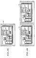
- Fig. 2 shows an exemplary case.
- the order prints shown in Fig. 2 carry the order number (Order no.), the order date and time (the time and date when the order was placed), the due date (the time when prints are to be ready), the name of the customer (who placed the order) and the customer ID, the trade name, the paper surface of prints, the information about how prints should be finished (the required image quality), the print fee (the amount payable), and the print size.
- the print pack Pa can accommodate only a limited number of prints.
- print system 10 no limit is placed on the number of prints that can be prepared in one order and if the number of prints that have been ordered in one order exceeds the maximum number of prints that can be accommodated in one print pack Pa, the prints for one order are distributed among a plurality of print packs Pa, into which they are accommodated and outputted from the print system 10.
- the maximum number of prints that can be accommodated in one print pack Pa is known and preset in DIC 12 as well.
- DIC 12 sets the relevant information and the like such that the prints of a particular order case will be accommodated within a plurality of print packs Pa; at the same time, an order print image is prepared in association with each of the print packs Pa. In other words, an order print image is prepared for each print pack Pa.
- the order print records the number of print packs (the quantity of packages) for each order or each case irrespective of whether it outputs one print pack Pa or yields more than one pack Pa.
- the operator can easily recognize that the prints of a particular case are distributed among a plurality of print packs.
- the piece of information that is to be recorded on each order print to show that the prints of a particular order or a particular case are distributed among a plurality of print packs Pa is by no means limited to the total number of print packs Pa for each case. If desired, the total number of print packs Pa for a particular case may be successively combined with the numbers assigned to the individual print packs Pa, as exemplified by 1/3, 2/3 and 3/3 with the numeral 3 referring to the total number of print packs Pa. In the example shown in Fig. 2B for the case where more than one pack Pa is outputted, the order print shows not only the quantity of packages but also the total number of print packs Pa in combination with the numbers assigned to the individual print packs Pa. However, this is not the sole case of the present invention and either piece of information may be omitted.
- DIC 12 performs image processing on each image and it also generates an order print image; then, for each order, DIC 12 relates the order information to the images (the product images and the order print image) and sends these images to the printer 14. DIC 12 also relates the order information to the information about the number of print packs for the case of interest and sends it to the printer 14. Furthermore, DIC 12 generates sorting information in relation to the images for one print pack and sends it to the printer 14. It should be noted here that in the present invention, the information about the number of print packs Pa need not be sent to the printer 14 in all orders (i.e.
- the images are sent in such a sequence that the order print is positioned on top of any other prints in a print pack Pa.
- the prints traveling through the printer 14 are fed into a packaging enclosure sheet S as they are stacked with the image bearing surface of each print facingupward; therefore, the images of each case are supplied into the printer such that the order print presents the last image in the print pack Pa.
- the printer 14 in the print system 10 comprises the exposing assembly 16, the processor 18, the packer 20, and the control assembly 22.
- the control assembly 22 controls the driving and action of each site in the printer 14.
- the control assembly 22 also receives the order information and the information about the number of print packs for each case from DIC 12 and supplies the necessary information to the packer 20 and various other sites.
- the exposing assembly 16 cuts the photosensitive material A to a size that allows for prints to be prepared, records a back print on the cut sheet of photosensitive material A, exposes the photosensitive material A to a light beam L modulated in accordance with the product images and the order print image sent from the DIC 12, thereby recording a latent image, and then supplies the exposed photosensitive material A into the processor 18 (a developing section 38).
- the illustrated printer 10 is so adapted that it can be loaded with two magazines 26.
- the photosensitive material A is drawn out of either magazine 26 and cut by a cutter 34 in accordance with the print size; thereafter, the photosensitive material A is subjected to back printing with the back printer 28 and supplied into the auxiliary scan transport roller pairs 32.
- the exposing unit 30 is supplied with the product images and the order print image (their image data).
- the light beam L modulated in accordance with the product images or the order print image is deflected in the main scanning direction to strike the predetermined exposing position.
- the photosensitive material A is transported in an auxiliary scanning direction perpendicular to the main scanning direction and in register with the predetermined exposing position by means of the auxiliary scan transport roller pairs 32 located on opposite sides of the exposing position in the direction of its transport.
- the photosensitive material A is exposed by two-dimensional scanning with the imagewise modulated light beam L, whereupon a latent image is recorded on its entire surface.
- the individual sheets of the photosensitive material A are exposed in such a manner that the order print will be on the top of the stack in a print pack.
- the prints P traveling through the printer 14 are fed into an enclosure sheet S as they are stacked with the image bearing surface of each print facing upward. Therefore, the sequence of exposing the individual sheets of photosensitive material A is such that after all of the product images in one print pack Pa have been exposed, the order print image is exposed.
- the photosensitive material A which has a latent image recorded thereon by means of the exposing unit 30 and the auxiliary scan transport roller pairs 32 is subsequently supplied into the processor 18.
- the photosensitive material A that has a latent image formed in the exposing assembly 16 and which has been supplied into the processor 18 first enters the developing section 38 where it is developed in a developing tank 42 to render the latent image visible; the photosensitive material A then goes into a bleach-fixing tank 44 where the visible image is bleached and fixed; thereafter, the photosensitive material A is successively washed in four washing tanks 46 and transported into the drying section 40.
- the sheets of developed photosensitive material A are then dried in the drying section 40 with a heater, warm air or some other means and discharged as prints P (product prints and an order print) from a discharging section 48 through an exit roller pair 50 into the packer 20 (more specifically a collecting section 56).
- Print P that are too large to be accommodated in a print pack are not transported into the packer 20 but are discharged into a large-size print discharging section 52 that is positioned upward of the discharging section 48.
- Transport path switching between the two discharging sections may be realized by any known method such as by using a switch guide.
- the packer 20 collects the prints P and puts them into an enclosure to make a print pack P in accordance with the order information. Having this function, the packer 20 comprises the collecting section 56, a transport section 58, a feeding section 60, a sheet supply section 62 for supplying the packaging enclosure sheet S, an opening providing means 64, a seal-and-cut means 66, and a product accommodating section 68.
- Fig. 3 shows an outline of the collecting section 56, the transport section 58, and the feeding section 60.
- Fig. 3A is a front view (as seen from the same direction as is Fig. 1) and Fig. 3B is a plan view.
- the collecting section 56 collects the prints P as have been discharged through the exit roller pair 50; at the same time, it rearranges the prints P in a direction perpendicular to the direction of their transport (which is hereinafter referred to as the transverse direction) and transports them to the downstream transport section 58.
- the collecting section 56 has a conveyor 72 and width-adjusting guides 74 (indicated by a dashed line in Fig. 3A).
- the conveyor 72 is a known belt conveyor consisting of a pair of rollers 76 and an endless belt 78 stretched between these rollers 76 and it transports the collected prints P to the downstream transport section 58.
- Each of the rollers 76 is axially supported on support plates 76a (which are omitted from Fig. 3A for structural clarity and so are the other support plates).
- the prints P are collected with their image bearing side facing up.
- the print stack which is to be fed into the packaging sheet S has the order print on the top.
- the conveyor 72 is positioned downward of the exit roller pair 50 in a vertical direction whereas in the direction of transport of the prints P, the upstream roller 76 is in substantially the same position as but slightly downstream of the exit roller pair 50.
- the width of the endless belt 78 is smaller than the minimum size of the corresponding print P in the transverse direction.
- the width-adjusting guides 74 are guide members in plate form that consist of two plates positioned on opposite sides of the conveyor 72 in the transverse direction.
- the timing on which the width-adjusting guides 74 are driven in the collecting section 56 (namely, the timing on which the prints P are rearranged in the transverse direction) is not limited in any particular way and after a predetermined number of prints P that depends on how many prints P in stack can be moved have been discharged and collected, the width-adjusting guides 74 may be driven to rearrange those prints P before the next print P is discharged.
- the holding force of the width-adjusting guides 74 is preferably small.
- photographic prints in the illustrated example have a comparatively large friction coefficient on their surface, so if too many prints are stacked, an unduly great force will be required to perform effective width adjustment.
- the prints can be rearranged more positively and orderly by performing widthwise adjustment each time a small enough number of prints are collected.
- the width-adjusting guides 74 be driven to rearrange the prints P each time an appropriately determined number of prints P which is not more than five have been discharged; more preferably, the width-adjusting guides 74 are driven to rearrange the prints P each time two prints, most preferably one print, has been discharged.
- the transport section 58 is a site that receives the print stack, or the stack of prints P as have been collected and rearranged in the transverse direction by the collecting section 56, and which transports the print stack to the downstream feeding section 60. Having this function, the transport section 58 has conveyors 80, a curl-flattening roller 82, and a means (not shown) for oscillating the conveyors 80.
- the conveyor 80 is a known belt conveyor which consists of an endless belt 84 and a pair of rollers 86 between which the belt 84 is stretched. Each of the rollers 86 is axially supported on support plates 86a.
- the transport section 58 has two conveyors 80 that are positioned on the sides of the conveyor 72 in the transverse direction in the collecting section 56 in such a way that the rotating axis of the roller 76 downstream of the conveyor 72 and the rotating axis of each of the rollers 86 upstream of the conveyor 80 are aligned in a line that extends in the transverse direction.
- the transport region in the collecting section 56 overlaps the transport region in the transport section 58, ensuring that the print stack is transported positively from the collecting section 56 to the transport section 58.
- the support plates 86a for each of the two conveyors 80 are integral to each other.
- the conveyor 72 in the collecting section 56 and the conveyors 80 are positioned in such a way that the transport path in the collecting section 56 aligns linearly with the transport path in the transport section 58 when the print stack is transported from the former to the latter.
- each conveyor 80 is raised so that it is inclined downward in the direction of transport (as indicated by the dashed lines in Fig. 3A).
- a wall 88 is erected on the surface of the endless belt 84 of each conveyor 80, with the height of the wall 88 being determined by various factors including the maximum number of prints P that can be accommodated in one print pack Pa.
- the transport section 58 receives the print stack from the collecting section 56.
- each of the conveyors 80 in the transport section 58 is driven in such a controlled manner that at the time the print stack starts to be transported into the transport section 58, the wall 88 is located downstream of the print stack but at the time the transport of the print stack into the transport section 58 ends, the wall 88 comes to be situated above the conveyor 80.
- each endless belt 84 preferably has a projection, a wall or other pushing member 84a that will be situated upstream of the print stack at the time the whole of it sits on the conveyor 80.
- the as-dried print P typically curls downward in such a way that the image bearing side caves in (to form a trough).
- the prints P are ejected from the discharging section 48 into the collecting section 56 with their image bearing side facing up.
- the curl-flattening roller 82 is provided as a preferred embodiment of the present invention and depresses the print stack from above so that the curl of each print P is flattened out to straighten the print P.
- the curl-flattening roller 82 is axially supported on an end of a rod-shaped arm 90.
- the arm 90 is supported to be capable of oscillating on an axis 92 at the other end which is away from the curl-flattening roller 82; by oscillating the arm 90 with a drive source (not shown), the curl-flattening roller 82 pivots to move up and down as indicated by the two-head arrow "b" in Fig. 3A.
- the curl-flattening roller 82 Before the print stack is transported from the collecting section 56 into the transport section 58, the curl-flattening roller 82 has been moved upward. When the print stack is transported from the collecting section 56 into the transport section 58, the curl-flattening roller 82 is moved downward to depress the print stack from above to remove its curl.
- the curl-flattening roller 82 may be a driven roller or a drive roller which rotates in synchronism with the transport of the print stack into the feeding section 60 which is to be described later in this specification.
- Each of the conveyors 80 in the transport section 58 is adapted to be capable of oscillating about the rotating axis of the downstream roller 86; if, for example, the upstream roller 86 is lifted by a drive source (not shown), the conveyor 80 is inclined in such a way that its downstream end is at the lower position as indicated by the dashed lines in Fig. 3A, whereupon it is inclined by the same (or substantially the same) angle as a conveyor 96 in the feeding section 60 to be described later. Note that in synchronism with this oscillation of each conveyor 80, the curl-flattening roller 82 also moves so that it keeps depressing the print stack even when the conveyor 80 is in an inclined state.
- each conveyor 80 and the conveyor 96 in the feeding section 60 are positioned in such a way that the rotating axes of the two rollers are aligned linearly and, hence, the overall transport path becomes linear at the time when the two conveyors form the same angle with the horizontal.
- the transport section 58 receives the print stack from the collecting section 56 with the conveyors 80 being held in a level state; thereafter, the upstream end of each conveyor 80 is raised so that it is inclined by the same angle as the conveyor 96 in the feeding section 60, and the print stack is transported into the feeding section 60 as the conveyor 96 forms a flat plane in combination with the conveyors 80.
- the transport section 58 transports the print stack into the feeding section 60 through the linear transport path as it slides down at (substantially) the same angle from the transport section 58 into the feeding section 60.
- the print stack it has received from the transport section 58 slides down at an angle with respect to the horizontal so that it is fed into the packaging sheet S.
- the feeding section 60 has the conveyor 96, a shutter 98, a guide plate 100, and two curl-flattening rollers 102 that are axially supported on the guide plate 100.
- the conveyor 96 is a belt conveyor which consists of a pair of rollers 104, an endless belt 106 that is stretched between the rollers 104, as well as a pushing member 106a and a wall 106b that are erected on the surface of the endless belt 106; the conveyor 96 is so positioned that it is inclined downward in the direction of transport.
- Each of the rollers 104 is axially supported on support plates 104a which are of the same type as the aforementioned support plates 76a and 86a.
- the conveyor 96 lies between the two conveyors 80 in such a way that the rotating axis of the roller 104 upstream of the conveyor 96 in the feeding section 60 and the rotating axis of each of the rollers 86 downstream of the conveyors 80 in the transport section 58 are aligned in a line that extends in the transverse direction.
- the transport region in the transport section 58 overlaps the transport region in the feeding section 60 (the conveyor 96), ensuring positive transport of the print stack while at the same time, the transport path in the transport section 58 aligns linearly in a more preferred way with the transport path in the feeding section 60.
- the above-described downwardly inclined transport causes the print stack to be fed into the packaging sheet S as it is guided by the shutter 98 to be described later (in particular, doors 130).
- the pushing member 106a in the form of a prism (wall) is erected on the surface of the endless belt 106 of the conveyor 96 as a preferred embodiment of the present invention.
- the pushing member 106a pushes the upstream end of the print stack so it slides downward on the conveyor 96 in the direction of its transport as it is fed into the packaging sheet S.
- the conveyor 96 ensures that the print stack can be transported through the feeding section 60 and fed into the packaging sheet S in a more orderly and positive manner.
- the height of the pushing member 106a is not limited to any particular value. However, in order to ensure that all of the prints P in the print stack are pushed positively, the pushing member 106a preferably has a height greater than the maximum thickness of the print stack which is determined by various factors including the maximum number of the prints P that can be accommodated in one print pack Pa. If a member that regulates the height of the print stack as exemplified by the guide plate 100 in the illustrated example of the feeding section 60 to regulate the height of the print stack by flattening the curl of each print P, the height of the pushing member 106a may be set to be greater than that of the print stack's height regulating member.
- the shape of the pushing member 106a also is not limited in any particular way and aside from the prismatic (wall) shape used in the illustrated example, various other shapes can be adopted, including a bar (column).
- the conveyor 96 in the feeding section 60 also has the wall 106b erected on the surface of the endless belt 106 in order to prevent the collapse and untimely drop of the transported print stack.
- the height of the wall 106b may be determined in the same manner as the pushing member 106a.
- the positions of the pushing member 106a and the wall 106b are determined and the drive of the conveyor 96 is controlled in such a manner that when it receives the print stack from the transport section 58, the pushing member 106a will not get in the way of the print stack whereas the wall 106b is located downstream of the print stack (preferably in contact with the leading end face of the print stack) but at the time the transport of the print stack into the feeding section 60 ends, the pushing member 106a is located upstream of the print stack whereas both the pushing member 106a and the wall 106b are situated above the conveyor 96.
- the positions of the pushing members 84a and 106a are determined and the drive of the conveyors 80 and 96 is controlled in such a manner that as soon as (or slightly after) the pushing member 84a moves from above to below the conveyor 80 in the transport section 58, the pushing member 106a will move from below to above the conveyor 96.
- the speed at which the print stack is transported by the conveyor 96 (in the feeding section 60) so that it is fed into the packaging sheet S is not limited in any particular way; however, it should preferably be equal to or greater than the speed at which the print stack on the conveyor 96 will drop under gravity.
- the transport speed of the conveyor 96 does not have any particular upper limit.
- the transport speed of the print stack namely, the speed at which it is fed into the packaging sheet S (enclosure) is unduly fast
- the print stack is fed into the packaging sheet S with such a great force that it might potentially damage the enclosing sheet S or it may bounce back from the bottom and the like of the packaging sheet S so that some prints may potentially fly out.
- the transport speed of the conveyor 96 is preferably set in a range of about 1 to 2,000 mm/s.
- the angle of the conveyor 96 (the angle it forms with the horizontal), namely, the angle at which the print stack is oriented with respect to the packaging sheet S when it is fed into the latter (this angle may be called the angle of depression or the descending vertical angle) is not limited to any particular value, either, and any angle may be adopted as long as it allows the print stack to be fed into the packaging sheet S as it slides down at an angle with the horizontal.
- the print stack will bump against the surface of the packaging sheet S to upset its posture, potentially preventing the print stack from being fed into the packaging sheet S in a consistent manner.
- the angle at which the conveyor 96 is inclined to let the print stack be fed into the packaging sheet S is preferably in a range of 45 to 90°, more preferably in a range of 50 to 90°.
- the guide plate 100 is a member in plate form that is spaced from the endless belt 106 by a distance determined by the maximum height of the print stack which takes into account the maximum number of the prints in the print stack and their curl.
- the guide plate 100 has such a shape that the portion closer to the upstream end (through which the print stack is fed in) gently slopes downward to connect to a portion that is parallel to the transport surface of the conveyor 96. Note that the guide plate 100 has an opening that is formed in the central part in the transverse direction and through which the pushing member 106a and the wall 106b will pass.
- the guide plate 100 has three functions to perform: first, it regulates the height of the print stack as has been transported into the feeding section 60 by contacting its top; secondly, it axially supports the curl-flattening rollers 102; thirdly, it guides the print stack to come under the upstream curl-flattening roller 102 as it has been transported from the transport section 58. As already mentioned, each print P curls downward so it caves in, so the guide plate 100 contacts the two ends of the topmost print P in the transverse direction. Therefore, the guide plate 100 will never damage the image bearing side or any other parts of the print P to reduce its commercial quality.
- the curl-flattening rollers 102 depress the print stack from above so that the curl of the prints is flattened out to straighten them.
- the curl-flattening rollers 102 are provided as a preferred embodiment of the present invention and may be omitted if the paper quality and other features of the prints P are such that they will undergo only a small amount of curl.
- the shutter 98 mainly works as a guide member which guides the print stack in the transverse direction and in the direction it drops when it is fed into the packaging sheet S.
- the shutter 98 is composed of two doors 130 that are each axially supported at an end in the transverse direction and which open from the center outward to both sides as indicated by the two-head arrows "c" in Fig. 3B.
- Each of the doors 130 is a member in plate form that has a generally L-shaped cross section when it is seen from the direction of transport in an open state and it has two parts, a bottom 130 that supports (guides) the print stack from below as it is fed into the packaging sheet S and a sidewall 130b that is erected vertically from the bottom 130a.
- each door 130 (the outer end in the transverse direction in a closed state/the upstream end in the direction of transport in an open state) has a cylindrical prop 132 fixed thereto and this prop 132 is axially supported so that it can rotate about a longitudinal axis through the center. It should also be noted that the props 132 are positioned outside the transport path of the print stack in the transverse direction.
- the shutter 98 closes the transport path of the print stack with the sidewalls 130b of the two doors 130 as indicated by the solid lines in Fig. 3B.
- the props 132 rotate about the longitudinal axes through the center so that the two doors 130 swing from the center outward to open the shutter 98.
- the bottom 130a works as a guide member that supports the print stack from below (so that it prevents untimely drop of the print stack and guides it to travel in the direction it is to be fed in) whereas the sidewall 130b works as a member that guides the print stack in the transverse direction.
- the feeding section 60 and the sheet supply section 62 are so composed that when the shutter 98 is opened with a cut "c" (to be described later, through which the print stack is fed in) being widened to provide an opening, the opening ends of the doors 130 will be inserted into the cut "c" (i.e., opening of the shutter 98 causes the opening ends of the doors 130 to be inserted into the enclosure).
- the shutter 98 can function as a guide in a more advantageous manner.
- the packaging sheet S is a transparent tube which consists of two webs of sheet which are bonded together at the longitudinal edges.
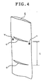
- the packaging sheet S has a plurality of cuts "c" that are formed in one side at an interval of "t” in correspondence to the length of one print pack Pa and which extend in a direction perpendicular to the longitudinal direction.
- the packaging sheet S is wound up as a sheet roll 110 and loaded in such an orientation that the side having the cuts "c" is directed toward the feeding section 60; the loaded packaging sheet S is transported in a predetermined path by various means including a guide roller pair 112 and a transport roller pair 114.
- the transport of the packaging sheet S stops at the time when one of the cuts "c" comes to a predetermined position that enables the feeding of the print stack from the feeding section 60, such as where the cut "c" is somewhat below the lower end of the feeding section 60.
- the opening providing means 64 serves to widen the cut "c" in the packaging sheet S in preparation for the print stack to be fed into the packaging sheet S (print pack Pa).
- the opening providing means 64 may hold the packaging sheet S by pinching their two constituent webs at positions just beneath the cut "c" and near the two opposite longitudinal sides of the packaging sheet S (such as the positions indicated by "v” in Fig. 4) and the opening providing means 64 is then moved inward to widen the cut "c".
- the means for widening the cut “c” is in no way limited to the aforementioned example and various known means may be adopted, including a method comprising pulling suckers attached to areas under the cut "c” so that it is widened and a method of widening the cut "c” using a suitable tool.
- wind typically from a fan is preferably blown from above into the cut "c" so as to increase the degree of its opening and inflate the packaging sheet S.
- the wind typically from a fan may be blown from above into the cut "c" as it forms a small angle with the packaging sheet S rather than being parallel to it and this is more preferred for the purpose of increasing the degree of its opening and inflating the packaging sheet S.
- the packaging sheet S stands by as it is suspended from the guide roller pair 112 with its lower part being guided by the transport roller pair 114.
- the prints P that have been transported through the discharging section 48 pass through the exit roller pair 50 to be discharged and collected in the collecting section 56 (on the conveyor 72).
- the width-adjusting guides 74 are moved inward on a predetermined timing, say, each time one print P is discharged, so that the prints P are collected in register in the transverse direction.
- the sort information supplied from the DIC 12, the counted number of prints, or any other information may be used to detect the fact that all of the prints S to be accommodated in one print pack Pa (i.e., the product prints and the order print) have been collected in the collecting section 56 and when this detection is effected, the conveyor 72 in the collecting section 56 and the conveyors 80 in the transport section 58 are driven in synchronism so that the print stack is transported from the collecting section 56 to the transport section 58.
- the curl-flattening roller 82 is moved downward so that the print stack is depressed from above to flatten the curl of each print; then, the upstream rollers 86 are raised to bring the conveyor 80 into an inclined state as indicated by the dashed lines in Fig. 3A.
- the conveyors 80 and the conveyor 96 are driven in synchronism so that the print stack is transported from the transport section 59 into the feeding section 60, in which the print stack is transported downward at an angle until it is fed through the wide-open cut "c" into the packaging sheet S.
- the opening ends of the doors 130 are within the packaging sheet S, with the bottom 130a of each door 130 guiding the print stack from below and the sidewall 130b guiding the print stack in the transverse direction; as a result, the print stack can be fed into the packaging sheet S in a positive and orderly manner.
- the opening providing means 64 releases the packaging sheet S (and, if necessary, the fan is stopped); subsequently, the sheet roll 110, the guide roller pair 112 and the like are rotated so that the packaging sheet S is supplied to the position where the cut "c" reaches the seal-and-cut means 66.
- the seal-and-cut means 66 serves two functions: first, it closes the packaging sheet S by fusing together (heat sealing) the two constituent webs of sheet with heat, typically from a heater; second, it thermally cuts the enclosing sheet S into separate print packs Pa.
- the heater as the seal-and-cut means 66 has a tiny projection at the center (in the direction of transport of the packaging sheet S) which extends in the transverse direction.
- the above-described supply of the packaging sheet S stops at the position where the projection at the center of the heater coincides with the cut "c". Then, the heater as the seal-and-cut means 66 is depressed onto the packaging sheet S so that the sheet is sealed (closed) both above and below the cut "c" and the central projection cuts (fuses apart) the packaging sheet S along the cut "c".
- the lower end of the packaging sheet S for accommodating the prints P (at which it connects to the sheet roll 110) is closed and, at the same time, the upper end of the packaging sheet S accommodating one lot of prints P for one order is closed and cut off, whereby one complete print pack Pa is produced.
- the print pack Pa accommodating one lot of prints P for one order is transported downward by means of the transport roller pair 114 and another transport roller pair 116, through which it is guided by a guide 118 to be accommodated in the product accommodating section 68.
- the printer 10 has been supplied from the DIC 12 with information about the number of print packs Pa to be prepared for each case.
- the packer 20 performs in different ways depending on the order.
- two adjacent print packs Pa are only sealed/closed at the upper and lower ends of each print pack Pa but they are not cut off; hence, as shown conceptually in Fig. 2B, a plurality of print packs Pa for one order are discharged in a continuous form into the product accommodating section 68.
- the heater as the seal-and-cut means 66 is so designed that the projection can be controlled for heating independently of other regions and only the sealing of the print packs P is performed without heating the projection.
- the sealing and/or cutting conditions are modified, as by selectively lowering the temperature of the projection, shortening the duration of sealing/cutting with the heater (seal-and-cut means 66), reducing the pressing force of the heater, or lowering the temperature of the heater; as a result, each print pack is sealed but adjacent print packs are incompletely cut apart, so that a plurality of print packs Pa for one order are discharged in a continuous form into the product accommodating section 68.
- the present invention ensures that the print packs Pa for one order are not cut apart but remain connected during subsequent handling. This not only provides ease in verification and search of prints (or print packs) but also achieves considerable reduction in the amount of time and effort required to return the completed print packs to the customer.
- the print packs prepared in accordance with the present invention are characterized in that a piece of information that shows that the prints of a particular case are distributed among a plurality of print packs Pa, as exemplified by the number of print packs of that particular case, is indicated on the order print and this feature, combined with the uncut print packs, contributes to a further improvement in the efficiency of print verification and other operations.
- the sealing and/or cutting conditions for ensuring that adjacent print packs are incompletely cut apart may be set by preliminary experimentation, simulation and the like in consideration of various factors including the constituent material of the enclosure.
- the foregoing embodiments relate to the case of applying the printing apparatus of the present invention in photographic printers of a type that scan-exposes a photosensitive material (photographic paper) to form a latent image and which performs a specified procedure of development and subsequent processing to prepare prints.
- This is not the sole case of the present invention and the concept of the invention is also applicable with advantage to an ink-jet printer, an electrophotographic printer, a thermal printer, and various other types of printers (or printing apparatuses).
Landscapes
- Engineering & Computer Science (AREA)
- Physics & Mathematics (AREA)
- General Physics & Mathematics (AREA)
- Multimedia (AREA)
- Signal Processing (AREA)
- Mechanical Engineering (AREA)
- Spectroscopy & Molecular Physics (AREA)
- General Engineering & Computer Science (AREA)
- Photographic Processing Devices Using Wet Methods (AREA)
- Projection-Type Copiers In General (AREA)
- Packaging Of Special Articles (AREA)
- Auxiliary Devices For And Details Of Packaging Control (AREA)
Applications Claiming Priority (1)
| Application Number | Priority Date | Filing Date | Title |
|---|---|---|---|
| JP2005236445A JP2007052170A (ja) | 2005-08-17 | 2005-08-17 | プリント装置 |
Publications (2)
| Publication Number | Publication Date |
|---|---|
| EP1754613A2 true EP1754613A2 (de) | 2007-02-21 |
| EP1754613A3 EP1754613A3 (de) | 2010-10-06 |
Family
ID=37524169
Family Applications (1)
| Application Number | Title | Priority Date | Filing Date |
|---|---|---|---|
| EP06017083A Withdrawn EP1754613A3 (de) | 2005-08-17 | 2006-08-16 | Druckgerät |
Country Status (3)
| Country | Link |
|---|---|
| US (1) | US20070041025A1 (de) |
| EP (1) | EP1754613A3 (de) |
| JP (1) | JP2007052170A (de) |
Families Citing this family (1)
| Publication number | Priority date | Publication date | Assignee | Title |
|---|---|---|---|---|
| JP5233369B2 (ja) * | 2008-04-01 | 2013-07-10 | 株式会社リコー | 画像形成装置 |
Citations (1)
| Publication number | Priority date | Publication date | Assignee | Title |
|---|---|---|---|---|
| JP2003035938A (ja) | 2001-07-25 | 2003-02-07 | Noritsu Koki Co Ltd | 写真処理機 |
Family Cites Families (8)
| Publication number | Priority date | Publication date | Assignee | Title |
|---|---|---|---|---|
| US3278015A (en) * | 1964-07-30 | 1966-10-11 | Louis R Bernstein | Combination envelope and display device |
| US3414122A (en) * | 1967-12-29 | 1968-12-03 | Eastman Kodak Co | Mailing carton for photographic prints and/or their negatives |
| US3733770A (en) * | 1971-03-03 | 1973-05-22 | Processing Lab Inc | Processor's method and apparatus for packing photographs |
| US3718807A (en) * | 1971-04-16 | 1973-02-27 | Eastman Kodak Co | Method and apparatus for facilitating the packaging and pricing of photographic prints |
| US4139978A (en) * | 1977-04-11 | 1979-02-20 | Pako Corporation | Automatic photographic print and film packaging mechanism |
| US4114349A (en) * | 1977-04-11 | 1978-09-19 | Pako Corporation | Automatic sorting, conveying and packing mechanism for photographic prints |
| US5070677A (en) * | 1991-02-20 | 1991-12-10 | Ray Hicks | Automated photographic print bagger |
| IT1297239B1 (it) * | 1996-09-27 | 1999-08-09 | Siral Srl | Imbustatrice automatica di foto stampe e simili |
-
2005
- 2005-08-17 JP JP2005236445A patent/JP2007052170A/ja not_active Withdrawn
-
2006
- 2006-08-16 EP EP06017083A patent/EP1754613A3/de not_active Withdrawn
- 2006-08-17 US US11/505,413 patent/US20070041025A1/en not_active Abandoned
Patent Citations (1)
| Publication number | Priority date | Publication date | Assignee | Title |
|---|---|---|---|---|
| JP2003035938A (ja) | 2001-07-25 | 2003-02-07 | Noritsu Koki Co Ltd | 写真処理機 |
Also Published As
| Publication number | Publication date |
|---|---|
| US20070041025A1 (en) | 2007-02-22 |
| EP1754613A3 (de) | 2010-10-06 |
| JP2007052170A (ja) | 2007-03-01 |
Similar Documents
| Publication | Publication Date | Title |
|---|---|---|
| US6459471B2 (en) | Image reproduction apparatus with compact, low-waste digital printer | |
| US4777514A (en) | Laser computer output microfilm camera | |
| EP1754613A2 (de) | Druckgerät | |
| JP3632136B2 (ja) | 写真プリントの生産方法および生産設備 | |
| US20060165457A1 (en) | Print production method, print production system, print order slip, print containing bag, and print product | |
| JP2006323205A (ja) | パッキング装置 | |
| JP2006327672A (ja) | パッキング装置 | |
| JP2006251595A (ja) | プリント生産システム | |
| JP2006323201A (ja) | パッキング装置、それを用いたプリント作成装置およびパッキング方法 | |
| JP2006323200A (ja) | パッキング装置 | |
| JP3613490B2 (ja) | 熱現像装置 | |
| US20060204287A1 (en) | Image recording apparatus and a print system using the same | |
| US7637676B2 (en) | Photographic pack and print system | |
| JP3355843B2 (ja) | インデックスプリント作成供給装置および写真焼付現像装置 | |
| JP2003035938A (ja) | 写真処理機 | |
| US7463332B2 (en) | Image forming method and apparatus | |
| JP2006227476A (ja) | 画像形成装置、プリントパック陳列棚およびプリント料金計算装置 | |
| US20060260960A1 (en) | Packing apparatus, print producing apparatus using the same, and packing method | |
| JP2011191866A (ja) | シート受渡装置 | |
| JP3726573B2 (ja) | 感光材料の幅方向位置調節方法及び写真処理装置 | |
| JP2000347381A (ja) | シート状体搬送装置及び写真処理装置 | |
| JP2007052353A (ja) | プリント装置 | |
| JPH08248612A (ja) | 写真プリントの生産方法及び生産システム | |
| JP2006323206A (ja) | パッキング装置および方法 | |
| JP2007052123A (ja) | 画像形成装置およびプリント作製方法 |
Legal Events
| Date | Code | Title | Description |
|---|---|---|---|
| PUAI | Public reference made under article 153(3) epc to a published international application that has entered the european phase |
Free format text: ORIGINAL CODE: 0009012 |
|
| AK | Designated contracting states |
Kind code of ref document: A2 Designated state(s): AT BE BG CH CY CZ DE DK EE ES FI FR GB GR HU IE IS IT LI LT LU LV MC NL PL PT RO SE SI SK TR |
|
| AX | Request for extension of the european patent |
Extension state: AL BA HR MK YU |
|
| RAP1 | Party data changed (applicant data changed or rights of an application transferred) |
Owner name: FUJIFILM CORPORATION |
|
| PUAL | Search report despatched |
Free format text: ORIGINAL CODE: 0009013 |
|
| AK | Designated contracting states |
Kind code of ref document: A3 Designated state(s): AT BE BG CH CY CZ DE DK EE ES FI FR GB GR HU IE IS IT LI LT LU LV MC NL PL PT RO SE SI SK TR |
|
| AX | Request for extension of the european patent |
Extension state: AL BA HR MK RS |
|
| AKY | No designation fees paid | ||
| REG | Reference to a national code |
Ref country code: DE Ref legal event code: R108 Effective date: 20110526 |
|
| STAA | Information on the status of an ep patent application or granted ep patent |
Free format text: STATUS: THE APPLICATION IS DEEMED TO BE WITHDRAWN |
|
| 18D | Application deemed to be withdrawn |
Effective date: 20110407 |