EP1754842A2 - Elément composite de plancher - Google Patents
Elément composite de plancher Download PDFInfo
- Publication number
- EP1754842A2 EP1754842A2 EP06016187A EP06016187A EP1754842A2 EP 1754842 A2 EP1754842 A2 EP 1754842A2 EP 06016187 A EP06016187 A EP 06016187A EP 06016187 A EP06016187 A EP 06016187A EP 1754842 A2 EP1754842 A2 EP 1754842A2
- Authority
- EP
- European Patent Office
- Prior art keywords
- profiles
- floor element
- composite floor
- element according
- frame
- Prior art date
- Legal status (The legal status is an assumption and is not a legal conclusion. Google has not performed a legal analysis and makes no representation as to the accuracy of the status listed.)
- Withdrawn
Links
Images




Classifications
-
- E—FIXED CONSTRUCTIONS
- E04—BUILDING
- E04B—GENERAL BUILDING CONSTRUCTIONS; WALLS, e.g. PARTITIONS; ROOFS; FLOORS; CEILINGS; INSULATION OR OTHER PROTECTION OF BUILDINGS
- E04B5/00—Floors; Floor construction with regard to insulation; Connections specially adapted therefor
- E04B5/02—Load-carrying floor structures formed substantially of prefabricated units
- E04B5/10—Load-carrying floor structures formed substantially of prefabricated units with metal beams or girders, e.g. with steel lattice girders
-
- E—FIXED CONSTRUCTIONS
- E04—BUILDING
- E04B—GENERAL BUILDING CONSTRUCTIONS; WALLS, e.g. PARTITIONS; ROOFS; FLOORS; CEILINGS; INSULATION OR OTHER PROTECTION OF BUILDINGS
- E04B5/00—Floors; Floor construction with regard to insulation; Connections specially adapted therefor
- E04B5/02—Load-carrying floor structures formed substantially of prefabricated units
- E04B5/04—Load-carrying floor structures formed substantially of prefabricated units with beams or slabs of concrete or other stone-like material, e.g. asbestos cement
-
- E—FIXED CONSTRUCTIONS
- E04—BUILDING
- E04C—STRUCTURAL ELEMENTS; BUILDING MATERIALS
- E04C2/00—Building elements of relatively thin form for the construction of parts of buildings, e.g. sheet materials, slabs, or panels
- E04C2/30—Building elements of relatively thin form for the construction of parts of buildings, e.g. sheet materials, slabs, or panels characterised by the shape or structure
- E04C2/38—Building elements of relatively thin form for the construction of parts of buildings, e.g. sheet materials, slabs, or panels characterised by the shape or structure with attached ribs, flanges, or the like, e.g. framed panels
- E04C2/384—Building elements of relatively thin form for the construction of parts of buildings, e.g. sheet materials, slabs, or panels characterised by the shape or structure with attached ribs, flanges, or the like, e.g. framed panels with a metal frame
Definitions
- the invention relates to a composite floor element for buildings constructed in modular design.
- the individual modules of such buildings are created in steel skeleton construction and are characterized by high factory prefabrication.
- the bottom elements of the known modules usually consist of a base frame of rolled U-profile with a plurality of spaced apart from each other in the frame cross members.
- the floor frame of the known floor elements encloses a mineral insulation.
- On the support of the frame a plywood planking and a possibly floating screed is applied.
- the static proof of the carrying capacity of the known floor element is carried out exclusively on the dimensioning of the floor crossmember. For this reason, it is necessary to generously dimension the steel profiles of the floor frame and the cross member used in these.
- the known floor elements are therefore relatively heavy and expensive.
- the floor structure is often introduced only when the modules are assembled into a building. This is also expensive because it reduces the potential degree of prefabrication.
- the invention is therefore an object of the invention to provide a floor element for building to be constructed in modular construction, which has a higher static load capacity than the previously known floor elements based on the weight.
- the floor element according to the invention should be distinguished by the highest possible factory prefabrication degree.
- a novel composite floor element for building constructed in modular construction comprising a frame and cross member made of metal profiles, preferably made of steel profiles, at least one DämmstoffIsoltechnik and at least one applied to the insulation layer of concrete, the insulation as a lost formwork is used for the concrete layer and where the profiles of the frame and the cross member partially from the concrete layer be recorded positively and form a supporting metal composite with the frame.
- the frame and the cross member are formed as U-profiles.
- the frame is composed of C-profiles, whereas the cross member are formed as U, double T, I or L profiles.
- the cross member are designed statically as a single-frame carrier.
- the upper leg of the profiles (upper straps) in installation position and / or partially the vertically extending sections of the profiles are embedded in the concrete.
- the upper chords and / or the vertically extending portions of the double T, I- or L-profiles have a profiled surface.
- top straps and / or the vertically extending profile sections of at least the cross member are provided with spaced holes, punched holes or embossments. If punched holes are provided in each case in the upper belts and / or in the vertically extending profile sections, these can be designed such that the punched-out material protrudes in the punching direction out of the relevant surface of the relevant leg of the profile.
- the perforations and / or punched holes are penetrated by the concrete of the concrete layer, so that a positive anchoring of the relevant profile is ensured in the concrete.
- insulation mineral wool can be provided.
- the insulating layer is clamped over hook-shaped holding elements with the concrete layer.
- the holding elements can be cast on one side in the concrete layer.
- the concrete layer can be designed as a steel fiber concrete with dispersed steel needles.
- a reinforcement in the form of steel mats or the like can be received by the concrete layer.
- the cross members are formed as L-profiles with cutouts, folds or slots, the steel mats can be held for example by the vertically extending legs of the cross member.
- the above-described variant of the floor element according to the invention makes use of the principle that the cross members are anchored in the concrete layer over at least part of their length (full dowelling).
- the concrete layer has an edge-side enclosure, for example in the form of angle profiles. These angle profiles are conveniently welded to the frame profiles.
- the compressive stresses are introduced into the concrete layer via the angular profiles provided at the edge. Additional measures for producing a positive connection between the cross members and the concrete layer are not required in this variant of the floor element (Endverdübelung).
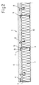
- the composite floor element (1) comprises a frame (2) and cross member (3) inserted therein, which can each be formed as U-profiles, the open side of the U-profile of the frame (2) facing inwards and the legs (4) of the frame (2) and the cross member (3) extend in the plane of the composite floor element (1).
- the legs (4) serving as upper girths (5) of the profiles are embedded in a concrete layer denoted by (6) which has been applied to a mineral wool insulating layer (7) as permanent formwork.
- the insulation layer (7) is additionally clamped by means of hook-shaped holding elements (8) on the concrete layer (6), wherein the holding elements (8) are also cast in one side in the concrete layer (6).
- the upper straps (5) of the cross member (3) are each provided with spaced holes (9), which are penetrated by the concrete of the concrete layer (6).
- the profiles of the cross member (3) of lesser strength than the profiles of the frame (2).
- the profiles of the frame (2) are welded together in the corners; the cross members (3) are also welded into the frame (2).
- the concrete layer (6) of the composite floor element is designed as a steel fiber concrete, i. in the concrete matrix steel needles (10) or the like are dispersedly distributed.
- the concrete layer does not necessarily have to be made of steel fiber concrete. This can be provided without reinforcement or alternatively or additionally with a Baustahlarmtechnik.
- FIG. 3 shows a further variant of the composite floor element (1) according to the invention.
- the cross members (3) are designed as L-profiles (15), wherein the L-profiles (15) have a shorter leg (16) extending approximately horizontally in the installed position. and a longer, approximately vertically in the installed position extending portion (17) exhibit.
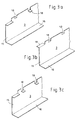
- the vertically extending portion (17) of the L-profiles (15) is partially embedded in the concrete layer (6) and partially penetrated by the concrete layer (6), as will be explained below with reference to Figures 3a - 3g.
- reinforcing steel meshes (11) can be embedded in the concrete layer (6) as an additional reinforcement.
- the structural steel mats (11) rest on recesses, folds or the like of the vertically extending legs (17) of the L-profiles.
- FIG. 3 a shows a perspective view of a variant of the cross member (3), in which the section (17) of the L profile to be partially embedded in the concrete layer (6) is provided with folds (18).
- the folds (18) extend alternately in different directions.
- the bends (18) extend only in one direction.
- the variant of the cross member (3) shown in Figure 3c In the variant of the cross member (3) shown in Figure 3d whose vertically extending portion (17) is provided with slots (19).
- the cross member (3) shown in Figure 3e is formed as a U-profile, wherein the upper flange (5) of the cross member (3) with a plurality of spaced-apart angle pieces (20) is provided.
- a further variant of the crossbeam (3) is finally shown in FIG. 3f, where the leg (17) extending vertically in the installed position is provided with perforations (9).
- FIG. 1 Another variant of the composite floor element according to the invention is shown in FIG.
- the frame (2) is composed of C-profiles (12).
- the cross members (3) are designed as lightweight double T-profiles (13). Additional measures for anchoring the cross member (3) in the concrete layer (6) are not provided in this embodiment of the composite floor element (1).
- the concrete layer (6) is bordered by angle sections (14), which are welded on the top side to the C-profiles (12) and via which the force diversion and the bonding effect are achieved.
- FIG. 3g shows a variant of the cross member 3 according to the invention, which is also designed essentially as an L profile whose vertical limbs are penetrated by the concrete layer both with bends (18) and with perforations (9).
- This variant of the L-profile (15) has proven to be particularly favorable in terms of the composite effect to be achieved.
- the combination of perforation (9) and fold (18) a permanent composite effect with the concrete layer (6) is achieved.
- perforation From the perforation can be added to increase the composite effect, if necessary, a steel bar. By the steel bar an additional anchoring is achieved. It will be apparent to those skilled in the art that the perforation may be only partially penetrated by the bar steel, for example, every second or third perforation (9) of a cross member (3) may be penetrated by a steel bar. The dimensions of the perforation (9) on the one hand and the bar steel on the other hand can be chosen so that the perforation (9) is additionally penetrated by concrete.
- the fold (18) absorbs forces acting perpendicular to the plane of the composite floor element (1) and thus reduces the edge pressure of the transverse beams (3), so that this contributes overall to the prevention of cracking in the concrete.
Landscapes
- Engineering & Computer Science (AREA)
- Architecture (AREA)
- Civil Engineering (AREA)
- Structural Engineering (AREA)
- Physics & Mathematics (AREA)
- Electromagnetism (AREA)
- Building Environments (AREA)
- Floor Finish (AREA)
- Panels For Use In Building Construction (AREA)
Applications Claiming Priority (1)
| Application Number | Priority Date | Filing Date | Title |
|---|---|---|---|
| DE200510038996 DE102005038996A1 (de) | 2005-08-16 | 2005-08-16 | Verbund-Bodenelement |
Publications (2)
| Publication Number | Publication Date |
|---|---|
| EP1754842A2 true EP1754842A2 (fr) | 2007-02-21 |
| EP1754842A3 EP1754842A3 (fr) | 2009-01-07 |
Family
ID=37389100
Family Applications (1)
| Application Number | Title | Priority Date | Filing Date |
|---|---|---|---|
| EP06016187A Withdrawn EP1754842A3 (fr) | 2005-08-16 | 2006-08-03 | Elément composite de plancher |
Country Status (2)
| Country | Link |
|---|---|
| EP (1) | EP1754842A3 (fr) |
| DE (1) | DE102005038996A1 (fr) |
Cited By (4)
| Publication number | Priority date | Publication date | Assignee | Title |
|---|---|---|---|---|
| CN105064577A (zh) * | 2015-08-05 | 2015-11-18 | 北京建工华创科技发展股份有限公司 | 一种预制混凝土组合楼板 |
| GB2607112A (en) * | 2021-05-29 | 2022-11-30 | Brennan Enterprise Ltd | A lightweight composite structural construction panel |
| WO2022254190A1 (fr) * | 2021-05-29 | 2022-12-08 | Brennan Enterprise Limited | Panneau de construction à structure composite léger |
| SE2450221A1 (sv) * | 2024-02-22 | 2025-08-23 | Nokon Holding Ab | System och förfarande för att bygga ett hus |
Family Cites Families (6)
| Publication number | Priority date | Publication date | Assignee | Title |
|---|---|---|---|---|
| AT301131B (de) * | 1970-10-30 | 1972-08-25 | Josef Weidinger | Dach- und Deckendiele |
| US4602467A (en) * | 1984-07-02 | 1986-07-29 | Schilger Herbert K | Thin shell concrete wall panel |
| US4885884A (en) * | 1988-05-25 | 1989-12-12 | Schilger Herbert K | Building panel assembly |
| US5758463A (en) * | 1993-03-12 | 1998-06-02 | P & M Manufacturing Co., Ltd. | Composite modular building panel |
| US6041561A (en) * | 1997-08-22 | 2000-03-28 | Wayne Leblang | Self-contained molded pre-fabricated building panel and method of making the same |
| JP3038171B2 (ja) * | 1997-08-28 | 2000-05-08 | ナショナル住宅産業株式会社 | 床パネル |
-
2005
- 2005-08-16 DE DE200510038996 patent/DE102005038996A1/de not_active Withdrawn
-
2006
- 2006-08-03 EP EP06016187A patent/EP1754842A3/fr not_active Withdrawn
Cited By (4)
| Publication number | Priority date | Publication date | Assignee | Title |
|---|---|---|---|---|
| CN105064577A (zh) * | 2015-08-05 | 2015-11-18 | 北京建工华创科技发展股份有限公司 | 一种预制混凝土组合楼板 |
| GB2607112A (en) * | 2021-05-29 | 2022-11-30 | Brennan Enterprise Ltd | A lightweight composite structural construction panel |
| WO2022254190A1 (fr) * | 2021-05-29 | 2022-12-08 | Brennan Enterprise Limited | Panneau de construction à structure composite léger |
| SE2450221A1 (sv) * | 2024-02-22 | 2025-08-23 | Nokon Holding Ab | System och förfarande för att bygga ett hus |
Also Published As
| Publication number | Publication date |
|---|---|
| EP1754842A3 (fr) | 2009-01-07 |
| DE102005038996A1 (de) | 2007-02-22 |
Similar Documents
| Publication | Publication Date | Title |
|---|---|---|
| DE60314459T2 (de) | Bauelement für die mantelbetonbauweise | |
| DE3408556C2 (fr) | ||
| DE3417330C1 (de) | Anschluss einer Ortbetonplatte an eine vorgefertigte Stuetze | |
| CH628107A5 (de) | Vorgespanntes deckenfeld, insbesondere zur herstellung von hochbaudecken, sowie verfahren zur herstellung von deckenfeldern. | |
| EP2405070A2 (fr) | Support en acier pour planchers préfabriqués | |
| AT407411B (de) | Bewehrungskörper für eine rippendecke aus gussbeton | |
| DE602005004450T2 (de) | Bewehrte verlorene Schalung, insbesondere für kreuzförmig bewehrte Böden, und damit hergestellter Boden | |
| EP1669505B1 (fr) | Poutre composite en acier-béton avec support ignifuge pour éléments de plafond | |
| EP1754842A2 (fr) | Elément composite de plancher | |
| DE19721165B4 (de) | Industriell vorfertigbare Leichtbau-Decken- oder -Dachtafeln | |
| DE69315656T2 (de) | Isolierende Mauerplatte | |
| DE4000956C2 (de) | Element für den Großtafelbau aus Beton | |
| EP0811731A1 (fr) | Structure et élément de plafond | |
| EP0106297A2 (fr) | Elément de construction pour la fabrication de murs en béton et mur de bâtiment fabriqué avec celui-ci | |
| DE3522382A1 (de) | Stahlbewehrung fuer bauteile | |
| DE1916904A1 (de) | Verbunddecke | |
| EP1227198A2 (fr) | Plancher composite d'acier | |
| DE202020100059U1 (de) | Schalungselement | |
| DE69001688T2 (de) | Verfahren zur befestigung von horizontalen balken an stahlsaeulen eines gebaeudes und ein nach diesem verfahren errichtetes gebaeude. | |
| DE3531185C1 (de) | Als Balken oder Stütze einsetzbares Bauelement aus profiliertem Stahlblech | |
| EP1312722B1 (fr) | Elément de construction pour une structure de plafond et structure de plafond dans un batiment | |
| DE29922297U1 (de) | Stahl-Beton-Decke | |
| DE29505448U1 (de) | Randschalungselement | |
| AT412295B (de) | Hohlwand - verbindungsträger für vollflächiges aufbringen von wärmedämmplatten auf der innenseiteder verlorenen schalung | |
| EP3315678A1 (fr) | Élément préfabriqué permettant de raccorder une plaque en porte à faux en béton à une construction |
Legal Events
| Date | Code | Title | Description |
|---|---|---|---|
| PUAI | Public reference made under article 153(3) epc to a published international application that has entered the european phase |
Free format text: ORIGINAL CODE: 0009012 |
|
| AK | Designated contracting states |
Kind code of ref document: A2 Designated state(s): AT BE BG CH CY CZ DE DK EE ES FI FR GB GR HU IE IS IT LI LT LU LV MC NL PL PT RO SE SI SK TR |
|
| AX | Request for extension of the european patent |
Extension state: AL BA HR MK YU |
|
| PUAL | Search report despatched |
Free format text: ORIGINAL CODE: 0009013 |
|
| AK | Designated contracting states |
Kind code of ref document: A3 Designated state(s): AT BE BG CH CY CZ DE DK EE ES FI FR GB GR HU IE IS IT LI LT LU LV MC NL PL PT RO SE SI SK TR |
|
| AX | Request for extension of the european patent |
Extension state: AL BA HR MK RS |
|
| RIC1 | Information provided on ipc code assigned before grant |
Ipc: E04B 5/10 20060101ALI20081202BHEP Ipc: E04C 2/38 20060101ALI20081202BHEP Ipc: E04B 5/02 20060101AFI20061117BHEP |
|
| AKX | Designation fees paid | ||
| STAA | Information on the status of an ep patent application or granted ep patent |
Free format text: STATUS: THE APPLICATION IS DEEMED TO BE WITHDRAWN |
|
| 18D | Application deemed to be withdrawn |
Effective date: 20090708 |
|
| REG | Reference to a national code |
Ref country code: DE Ref legal event code: 8566 |