EP1754895B1 - Speisentransportbehälter - Google Patents
Speisentransportbehälter Download PDFInfo
- Publication number
- EP1754895B1 EP1754895B1 EP06016087A EP06016087A EP1754895B1 EP 1754895 B1 EP1754895 B1 EP 1754895B1 EP 06016087 A EP06016087 A EP 06016087A EP 06016087 A EP06016087 A EP 06016087A EP 1754895 B1 EP1754895 B1 EP 1754895B1
- Authority
- EP
- European Patent Office
- Prior art keywords
- profile element
- transport container
- food transport
- container according
- connection
- Prior art date
- Legal status (The legal status is an assumption and is not a legal conclusion. Google has not performed a legal analysis and makes no representation as to the accuracy of the status listed.)
- Active
Links
Images


Classifications
-
- F—MECHANICAL ENGINEERING; LIGHTING; HEATING; WEAPONS; BLASTING
- F16—ENGINEERING ELEMENTS AND UNITS; GENERAL MEASURES FOR PRODUCING AND MAINTAINING EFFECTIVE FUNCTIONING OF MACHINES OR INSTALLATIONS; THERMAL INSULATION IN GENERAL
- F16B—DEVICES FOR FASTENING OR SECURING CONSTRUCTIONAL ELEMENTS OR MACHINE PARTS TOGETHER, e.g. NAILS, BOLTS, CIRCLIPS, CLAMPS, CLIPS OR WEDGES; JOINTS OR JOINTING
- F16B5/00—Joining sheets or plates, e.g. panels, to one another or to strips or bars parallel to them
- F16B5/0004—Joining sheets, plates or panels in abutting relationship
- F16B5/0032—Joining sheets, plates or panels in abutting relationship by moving the sheets, plates, or panels or the interlocking key parallel to the abutting edge
- F16B5/004—Joining sheets, plates or panels in abutting relationship by moving the sheets, plates, or panels or the interlocking key parallel to the abutting edge and using C-shaped clamps
-
- F—MECHANICAL ENGINEERING; LIGHTING; HEATING; WEAPONS; BLASTING
- F16—ENGINEERING ELEMENTS AND UNITS; GENERAL MEASURES FOR PRODUCING AND MAINTAINING EFFECTIVE FUNCTIONING OF MACHINES OR INSTALLATIONS; THERMAL INSULATION IN GENERAL
- F16B—DEVICES FOR FASTENING OR SECURING CONSTRUCTIONAL ELEMENTS OR MACHINE PARTS TOGETHER, e.g. NAILS, BOLTS, CIRCLIPS, CLAMPS, CLIPS OR WEDGES; JOINTS OR JOINTING
- F16B5/00—Joining sheets or plates, e.g. panels, to one another or to strips or bars parallel to them
- F16B5/06—Joining sheets or plates, e.g. panels, to one another or to strips or bars parallel to them by means of clamps or clips
- F16B5/0607—Joining sheets or plates, e.g. panels, to one another or to strips or bars parallel to them by means of clamps or clips joining sheets or plates to each other
- F16B5/0621—Joining sheets or plates, e.g. panels, to one another or to strips or bars parallel to them by means of clamps or clips joining sheets or plates to each other in parallel relationship
- F16B5/0635—Joining sheets or plates, e.g. panels, to one another or to strips or bars parallel to them by means of clamps or clips joining sheets or plates to each other in parallel relationship fastened over the edges of the sheets or plates
Definitions
- the present invention relates to a food transport container with an outer body, which comprises at least one component with a bevelled area, and with an inner body, which comprises at least one component with a bevelled area.
- food transport containers whose housing comprises an outer body and an inner body, for example for a heat compartment, wherein the outer body and the inner body are connected to each other by the outer body is circumferentially welded to the inner body.
- connection techniques mentioned above are also time-consuming and preparation-intensive.
- the components to be joined together must be positioned relative to one another by means of specially provided devices or by an additional employee.
- connection profile member for connecting juxtaposed plastic plates to form a composite outer wall of a container, such as a composter.
- the plates to be joined together are each provided with a bevelled area, and the connecting profile element comprises two receptacles for a respective folded portion of one of the plates to be joined together.
- the GB-A-2 287 517 discloses a connecting profile member for connecting side by side panels to form a composite outer wall of a housing for a motor vehicle.
- the CH 402 626 A discloses a connection profile element for connecting juxtaposed wall parts to form a composite outer wall of a drawer, in particular a side drawer for trucks or trailers.
- the GB 605 028 A discloses a connecting profile member for connecting side by side panels to form a composite outer wall of a piece of furniture, boat, canoe, building, train car, automobile, industrial vehicle, duty truck, airplane or the like.
- the present invention has for its object to provide a food transport container whose outer body and inner body are easily and quickly connected to each other.
- connection profile element comprises two receptacles adapted to the folded portions of the components to be joined, so that after the introduction of the folded portions of the components to be joined together in these shots, the two components by positive engagement relative to a relative movement relative to the connecting profile element and thus relative to a relative movement to each other are secured, at least in the transverse, preferably perpendicular, to the longitudinal direction of the connecting profile element extending directions.
- connection profile element Due to the positive connection between the connection profile element on the one hand and the two components to be joined together on the other hand, it is not necessary in the connection method, which uses the connection profile element, the components and / or the connection profile element by additional fasteners or by fabric bond, for example by welding or soldering together connect to. Furthermore, the components to be joined together need not be prepared by making through-holes.
- connection produced only by positive engagement between the two components to be joined together not only safe and durable, but can also be easily solved when needed again.
- connection profile element Any rework is not required when using the connection profile element.
- connection profile element that extend the receptacles for the folded portions of the components to be joined together in a longitudinal direction of the connection profile element.
- connection profile element A particularly secure hold of the two components to be connected to one another on the connection profile element is achieved if at least one of the receptacles for the folded regions has at least one arcuately curved section viewed in cross section.
- the arcuate curved section extends in a preferred embodiment over an arc angle of at least 45 °, preferably of at least 60 °.
- connection profile element particularly flexible
- the at least two receptacles are arranged mirror-symmetrically to each other.
- the connecting profile element is at least partially formed from a thermally insulating material.
- one of the components to be joined together can be used as the inner body and the other of the components to be joined together can be used as the outer body of the heated or cooled housing compartment of the food transport container.
- connection profile element can be produced in a particularly cost-effective manner if the connection profile element is formed at least partially from a plastic material.
- connection profile element may also be formed at least partially from a metallic material, for example aluminum.
- connection profile element can be designed as an aluminum continuous casting profile element.
- connection profile element any other materials are also suitable for the production of the connection profile element.
- connection profile element is integrally formed.
- the connecting profile element comprises at least two partial profile elements which can be displaced relative to one another. In this way, the introduction of the bent portions of the components to be joined together and / or the release of the connection between the two components to be joined together can be facilitated.
- connection profile element comprises at least two partial profile elements which can be displaced relative to one another, it can be provided that the at least two partial profile elements are connected to one another by a tongue and groove connection.
- a particularly secure hold of the two partial profile elements together is achieved when the spring of one partial profile element and / or the groove of the other partial profile element are formed substantially dovetail-shaped.
- At least one of the components of the outer body or of the inner body is made of a metallic material, preferably of a stainless steel material, in particular of a chromium-nickel steel.
- connection profile element for connecting components each formed of a metallic sheet material.
- connection profile element allows a simplified assembly when joining two components, each having a bent portion.
- connection profile element When using the connection profile element eliminates complex preparatory work, and there is no reworking of the interconnected components required.
- connection profile element If necessary, for example for maintenance, cleaning or repair, the connection between the components to be joined together produced by the connection profile element is easily solvable.
- the connecting profile element can be inexpensively manufactured as a plastic part.
- connection profile element which is formed at least partially from a thermally insulating material, allows a thermal separation between the components to be joined together.
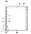
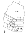
- FIG. 1 in cross-section as a whole shown food transport container 100, which in particular (by means of rollers) can be designed to include a housing 102, which in turn an outer skin of the housing 102 forming outer body 104, an inner skin of the housing 102 forming inner body 106 and between the outer carcass 104 and the inner body 106 disposed thermal barrier layer 108 of a thermally insulating plastic material, for example, polyurethane.
- a thermally insulating plastic material for example, polyurethane.
- the outer body 104 and the inner body 106 are formed of a metallic material, in particular of a stainless steel material, for example of a chromium-nickel steel.
- a side wall 112 of the outer body 104 and a side wall 114 of the inner body 106 are connected to each other by means of a connecting profile element 116.
- the connecting profile element 116 extends in a longitudinal direction 118 extending parallel to an edge of the housing 102 and has a substantially constant cross section in the longitudinal direction 118, which in particular consists of Fig. 2 can be seen.
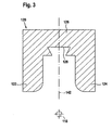
- connection profile element 116 comprises an in Fig. 3 shown in cross section outer partial profile element 120, which has a substantially U-shaped cross-section with a first leg 122 and a second leg 124 and a leg 122, 124 interconnecting web 126, wherein the web 126 on its inside with a cross-section dovetailed groove 128 is provided.
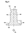
- connection profile element 116 comprises a cross-section in FIG Fig. 4 illustrated inner partial profile element 130, which has a substantially T-shaped cross-section, with a cross-sectionally substantially rectangular support portion 132 and a subsequent thereto the crossbar portion 134 which has two laterally projecting from the support portion 132 arcuately curved edge portions 136 which each - Seen in cross section - extend over a bend angle of 90 °.
- the support section 132 At the end of the support section 132 facing away from the crossbar section 134, the support section 132 is provided with a dovetail-shaped projection 138.
- Both the inner partial profile element 130 and the outer partial profile element 120 are each mirror-symmetrical to their respective longitudinal center planes 140 and 142 and thus also formed symmetrically to the longitudinal center plane of the connecting profile element 116.
- the inner partial profile element 130 is inserted into the outer partial profile element 120, that the projection 138 of the inner partial profile element 130 engages in the groove 128 of the outer partial profile element 120, that the two partial profile elements 120, 130 are displaceable relative to each other in the longitudinal direction 118 of the connecting profile element 116, while the two partial profile elements 120, 130 are secured by positive engagement against a relative movement transverse to the longitudinal direction 118 of the connecting profile element 116.
- the side wall 112 of the outer body 104 is on a parallel to the longitudinal direction 118 of the connecting profile element 116 extending first bending line 144 (see Fig. 2 ) and on a likewise parallel to the longitudinal direction 118 of the connecting profile element 116 extending second Abkantline 146 respectively folded by an angle of 90 °, so that between the first Abkantline 144 and the second Abkantline 146 a first folded portion 148 and between the second Abkantline 146 and parallel to the longitudinal direction 118 of the connecting profile member 116 extending edge 150 of the side wall 112 a second, two times folded region 152 of the side wall 112 of the outer body 104 is formed.
- the second folded portion 152 and the region of the second Abkantline 146 are received in the gap between the first leg 122 of the outer partial profile element 120 and the inner partial profile element 130, which thus forms a first receptacle 154 of the connecting profile element 116.
- the side wall 114 of the inner body 106 is also bent both at a parallel to the longitudinal direction 118 of the connecting profile element 116 extending first bending line 156 and at a further, parallel to the longitudinal direction 118 of the connecting profile element 116 extending second bending line 158 by 90 °, so that between the first Bending line 156 and the second Abkantline 158 a first folded portion 160 and between the second Abkantline 158 and a parallel to the longitudinal direction 118 of the connecting profile element 116 extending edge 162 of the side wall 114, a second, double beveled region 164 is formed.
- the second bent region 164 and the region of the second bending line 158 are received in the gap between the second leg 124 of the outer partial profile element 120 and the inner partial profile element 130, which thus forms a second receptacle 166 of the connection profile element 116 and which also has a gap width d which is slightly larger than the Thickness of the metal sheet from which the side wall 114 of the inner body 106 is formed.
- the crossbar portion 134 of the inner partial profile element 130 forms an undercut, which moves outward of the second folded portions 152 and 164 of the side walls 112 and 114 forward from the first receptacle 154 and from the second receptacle 166 of the connection profile element 116 out prevented.
- the first leg 122 and the second leg 124 of the outer partial profile element 120 form undercuts, which move apart and move out of the second folded portions 152 and 164 in a direction perpendicular to the longitudinal direction 118 of the connecting profile element 116 and perpendicular to the second folded portions 152 and 164 Prevent direction from the first receptacle 154 and out of the second receptacle 166 out.
- the second folded portions 152 and 164 of the side walls 112 and 114, respectively, could thus move relative to the connection profile element 116 only in its longitudinal direction 118; However, this movement along the longitudinal direction 118 of the connecting profile element 116 from the first receptacle 154 and out of the second receptacle 166 out in the mounted state of the housing 102 by the above the side walls 112, 114 disposed ceiling wall and by the below the side walls 112, 114 arranged Bottom wall of the housing 102 prevents.
- first Component 168 and a second component 170 are connected to each other by the connecting profile element 116 so that they can not be moved apart.
- the inner partial profile element 130 is formed from a thermally insulating plastic, so that the interconnected by the connecting profile element 116 components 168, 170 are thermally insulated from each other.
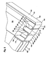
- connection between the first component 168 and the second component 170 can be easily achieved by connecting the connection profile element 116 as a whole or only the outer partial profile element 120 along the longitudinal direction 118 of the interconnected components 168 , 170 is deducted, as in Fig. 6 is shown.
- connection profile element 116 pushed onto the components 168, 170 that the second bevelled areas 152, 164 in the first receptacle 154 and in the second receptacle 166 of the connection profile element 116, as shown in Fig. 5 is shown.
- FIG. 7 illustrated second embodiment of a connecting profile element 116 differs from that in the Fig. 1 to 6 shown first embodiment only in that the outer partial profile element and the inner partial profile element are integrally connected to each other in this embodiment, so that the connecting profile element 116 is formed integrally as a whole.
- the first receptacle 154 for receiving the second folded portion 152 of the side wall 112 of the outer body 104 and the second receptacle 166 for receiving the second folded portion 164 of the side wall 114 of the inner body 106 are in this case by two, partially arcuately curved grooves 172 and 174th formed in the connection profile element 116.
- connection profile element 116 is made of a thermally insulating plastic.
Landscapes
- Engineering & Computer Science (AREA)
- General Engineering & Computer Science (AREA)
- Mechanical Engineering (AREA)
- Packages (AREA)
- Thermally Insulated Containers For Foods (AREA)
- Stackable Containers (AREA)
- Joining Of Corner Units Of Frames Or Wings (AREA)
Description
- Die vorliegende Erfindung betrifft einen Speisentransportbehälter mit einem Außenkorpus, der mindestens ein Bauteil mit einem abgekanteten Bereich umfasst, und mit einem Innenkorpus, der mindestens ein Bauteil mit einem abgekanteten Bereich umfasst.
- Aus dem Stand der Technik ist es bekannt, solche Bauteile, insbesondere Blechteile mit abgekanteten Bereichen, mittels Schweißen, Punktschweißen, Schrauben, Nieten, Kleben oder ähnlichen Fügetechniken miteinander zu verbinden.
- Insbesondere sind Speisentransportbehälter bekannt, deren Gehäuse einen Außenkorpus und einen Innenkorpus, beispielsweise für ein Wärmefach, umfasst, wobei der Außenkorpus und der Innenkorpus miteinander verbunden werden, indem der Außenkorpus umlaufend mit dem Innenkorpus verschweißt wird.
- Dieser Schweißvorgang verlangt jedoch umfangreiche Vorbereitungen und mehrere zeitaufwendige Arbeitsgänge. Insbesondere müssen die miteinander zu verbindenden Bauteile vor dem Schweißvorgang präzise relativ zueinander positioniert werden. Der Schweißvorgang selbst ist sehr zeitaufwendig. Nach dem eigentlichen Schweißvorgang sind umständliche Schleifarbeiten zur Nachbearbeitung erforderlich.
- Auch die weiteren, vorstehend erwähnten Verbindungstechniken sind zeitaufwendig und vorbereitungsintensiv.
- So müssen beim Punktschweißen die miteinander zu verbindenden Bauteile durch speziell hierfür vorgesehene Vorrichtungen oder durch einen zusätzlichen Mitarbeiter relativ zueinander positioniert werden.
- Bei einer Verbindung durch Schrauben oder Nieten müssen die miteinander zu verbindenden Bauteile durch Herstellen von Durchgangsöffnungen vorbereitet werden. Auch in diesem Fall ist die Montage durch die erforderliche genaue Positionierung oft umständlich und zeitaufwendig.
- Alle bislang verwendeten Techniken sind somit relativ zeitaufwendig, setzen eine Vielzahl unterschiedlichster Arbeitsgänge voraus oder benötigen einen zweiten Mitarbeiter, um sie durchführen zu können.
- Die
DE 298 09 629 U1 offenbart ein Verbindungsprofilelement zum Verbinden nebeneinander angeordneter Kunststoffplatten, um eine zusammengesetzte Außenwand eines Behälters, beispielsweise eines Komposters, zu bilden. Die miteinander zu verbindenden Platten sind mit jeweils einem abgekanteten Bereich versehen, und das Verbindungsprofilelement umfasst zwei Aufnahmen für jeweils einen abgekanteten Bereich einer der miteinander zu verbindenden Platten. - Die
GB-A-2 287 517 - Die
CH 402 626 A - Die
GB 605 028 A - Der vorliegenden Erfindung liegt die Aufgabe zugrunde, einen Speisentransportbehälter zu schaffen, dessen Außenkorpus und Innenkorpus einfach und rasch miteinander verbindbar sind.
- Diese Aufgabe wird erfindungsgemäß durch einen Speisentransportbehälter nach Anspruch 1 gelöst.
- Das Verbindungsprofilelement umfasst zwei an die abgekanteten Bereiche der miteinander zu verbindenden Bauteile angepasste Aufnahmen, so dass nach dem Einbringen der abgekanteten Bereiche der miteinander zu verbindenden Bauteile in diese Aufnahmen die beiden Bauteile durch Formschluss gegen eine Relativbewegung relativ zu dem Verbindungsprofilelement und somit gegen eine Relativbewegung relativ zueinander gesichert sind, und zwar zumindest in den quer, vorzugsweise senkrecht, zur Längsrichtung des Verbindungsprofilelements verlaufenden Richtungen.
- Aufgrund des Formschlusses zwischen dem Verbindungsprofilelement einerseits und den beiden miteinander zu verbindenden Bauteilen andererseits ist es bei der Verbindungsmethode, welche das Verbindungsprofilelement verwendet, nicht erforderlich, die Bauteile und/oder das Verbindungsprofilelement durch zusätzliche Befestigungselemente oder durch Stoffschluss, beispielsweise durch Schweißen oder Löten, miteinander zu verbinden. Ferner müssen die miteinander zu verbindenden Bauteile nicht durch die Herstellung von Durchgangsöffnungen vorbereitet werden.
- Ferner ist die nur durch Formschluss hergestellte Verbindung zwischen den beiden miteinander zu verbindenden Bauteilen nicht nur sicher und dauerhaft, sondern kann auch bei Bedarf leicht wieder gelöst werden.
- Irgendwelche Nacharbeiten sind bei Verwendung des Verbindungsprofilelements nicht erforderlich.
- Bei einer bevorzugten Ausgestaltung des Verbindungsprofilelements ist vorgesehen, dass sich die Aufnahmen für die abgekanteten Bereiche der miteinander zu verbindenden Bauteile in einer Längsrichtung des Verbindungsprofilelements erstrecken.
- Ein besonders sicherer Halt der beiden miteinander zu verbindenden Bauteile an dem Verbindungsprofilelement wird erzielt, wenn mindestens eine der Aufnahmen für die abgekanteten Bereiche im Querschnitt gesehen mindestens einen bogenförmig gekrümmten Abschnitt aufweist.
- Der bogenförmig gekrümmte Abschnitt erstreckt sich bei einer bevorzugten Ausgestaltung über einen Bogenwinkel von mindestens 45°, vorzugsweise von mindestens 60°.
- Um das Verbindungsprofilelement besonders flexibel einsetzen zu können, ist vorzugsweise vorgesehen, dass die mindestens zwei Aufnahmen spiegelsymmetrisch zueinander angeordnet sind.
- Um einen Wärmetransport zwischen den miteinander zu verbindenden Bauteilen zu erschweren oder ganz auszuschließen, ist es günstig, wenn das Verbindungsprofilelement zumindest teilweise aus einem thermisch isolierenden Material gebildet ist.
- Auf diese Weise kann das eine der miteinander zu verbindenden Bauteile als Innenkorpus und das andere der miteinander zu verbindenden Bauteile als Außenkorpus des gegenüber der Umgebung erwärmten oder gekühlten Gehäusefaches des Speisentransportbehälters verwendet werden.
- Das Verbindungsprofilelement lässt sich besonders kostengünstig herstellen, wenn das Verbindungsprofilelement zumindest teilweise aus einem Kunststoffmaterial gebildet ist.
- Alternativ hierzu kann das Verbindungsprofilelement auch zumindest teilweise aus einem metallischen Material, beispielsweise aus Aluminium, gebildet sein.
- Insbesondere kann das Verbindungsprofilelement als ein Aluminium-Strangguss-Profilelement ausgebildet sein.
- Grundsätzlich kommen auch beliebige andere Materialien für die Herstellung des Verbindungsprofilelements in Betracht.
- Bei einer besonders einfach herzustellenden Ausgestaltung des Verbindungsprofilelements ist vorgesehen, dass das Verbindungsprofilelement einstückig ausgebildet ist.
- Alternativ hierzu kann aber auch vorgesehen sein, dass das Verbindungsprofilelement mindestens zwei relativ zueinander verschiebbare Teilprofilelemente umfasst. Auf diese Weise kann das Einbringen der abgekanteten Bereiche der miteinander zu verbindenden Bauteile und/oder das Lösen der Verbindung zwischen den beiden miteinander zu verbindenden Bauteilen erleichtert werden.
- Wenn das Verbindungsprofilelement mindestens zwei relativ zueinander verschiebbare Teilprofilelemente umfasst, so kann vorgesehen sein, dass die mindestens zwei Teilprofilelemente durch eine Nut-Feder-Verbindung miteinander verbunden sind.
- Ein besonders sicherer Halt der beiden Teilprofilelemente aneinander wird dabei erzielt, wenn die Feder des einen Teilprofilelements und/oder die Nut des anderen Teilprofilelements im wesentlichen schwalbenschwanzförmig ausgebildet sind.
- Vorzugsweise ist mindestens eines der Bauteile des Außenkorpus beziehungsweise des Innenkorpus aus einem metallischen Material, vorzugsweise aus einem Edelstahlmaterial, insbesondere aus einem Chrom-Nickel-Stahl, gebildet.
- Besonders geeignet ist das Verbindungsprofilelement zum Verbinden von Bauteilen, die jeweils aus einem metallischen Blechmaterial gebildet sind.
- Das Verbindungsprofilelement ermöglicht eine vereinfachte Montage beim Zusammenfügen zweier Bauteile, die jeweils einen abgekanteten Bereich aufweisen.
- Bei Verwendung des Verbindungsprofilelements entfallen aufwendige Vorarbeiten, und es ist keine Nachbearbeitung der miteinander verbundenen Bauteile erforderlich.
- Die durch das Verbindungsprofilelement hergestellte Verbindung zwischen den miteinander zu verbindenden Bauteilen ist bei Bedarf, beispielsweise zur Wartung, Reinigung oder Reparatur, leicht lösbar.
- Das Verbindungsprofilelement kann kostengünstig als Kunststoffteil hergestellt werden.
- Ferner ermöglicht ein Verbindungsprofilelement, das zumindest teilweise aus einem thermisch isolierenden Material gebildet ist, eine thermische Trennung zwischen den miteinander zu verbindenden Bauteilen.
- Weitere Merkmale und Vorteile der Erfindung sind Gegenstand der nachfolgenden Beschreibung und der zeichnerischen Darstellung von Ausführungsbeispielen.
- In den Zeichnungen zeigen:
- Fig. 1
- einen schematischen horizontalen Querschnitt durch einen Speisentransportbehälter mit einem Außenkorpus und einem Innenkorpus, die durch ein Verbindungsprofilelement verbunden sind;
- Fig. 2
- eine vergrößerte Darstellung des Bereichs I aus
Fig. 1 ; - Fig. 3
- einen schematischen Querschnitt durch ein Außen-Teilprofilelement des Verbindungsprofilelements;
- Fig. 4
- einen schematischen Querschnitt durch ein Innen-Teilprofilelement des Verbindungsprofilelements;
- Fig. 5
- eine schematische perspektivische Darstellung des Verbindungs-profilelements mit daran aufgenommenen Bauteilen mit abgekanteten Bereichen und vollständig auf das Innen-Teilprofilelement aufgeschobenem Außen-Teilprofilelement;
- Fig. 6
- eine der
Fig. 5 entsprechende schematische perspektivische Darstellung, wobei das Außen-Teilprofilelement des Verbindungsprofilelements teilweise von dem Innen-Teilprofilelement abgezogen worden ist; und - Fig. 7
- einen schematischen Querschnitt durch eine zweite Ausführungsform eines Verbindungsprofilelements, welche einstückig ausgebildet ist.
- Gleiche oder funktional äquivalente Elemente sind in allen Figuren mit denselben Bezugszeichen bezeichnet.
- Ein in
Fig. 1 im Querschnitt als Ganzes dargestellter Speisentransportbehälter 100, der insbesondere (mittels Laufrollen) fahrbar ausgebildet sein kann, umfasst ein Gehäuse 102, welches seinerseits einen eine Außenhaut des Gehäuses 102 bildenden Außenkorpus 104, einen eine Innenhaut des Gehäuses 102 bildenden Innenkorpus 106 sowie eine zwischen dem Außenkorpus 104 und dem Innenkorpus 106 angeordnete Wärmedämmschicht 108 aus einem thermisch isolierenden Kunststoffmaterial, beispielsweise aus Polyurethan, umfasst. - Der Außenkorpus 104 und der Innenkorpus 106 sind aus einem metallischen Material, insbesondere aus einem Edelstahlmaterial, beispielsweise aus einem Chrom-Nickel-Stahl, gebildet.
- Im Bereich der stirnseitigen Zugangsöffnung 110 des Speisentransportbehälters 100, welche mittels einer (in den
Fig. 5 und6 dargestellten) an das Gehäuse 102 angelenkten Tür 111 verschließbar ist, sind jeweils eine Seitenwand 112 des Außenkorpus 104 und eine Seitenwand 114 des Innenkorpus 106 mittels eines Verbindungsprofilelements 116 miteinander verbunden. - Das Verbindungsprofilelement 116 erstreckt sich in einer parallel zu einer Kante des Gehäuses 102 erstreckenden Längsrichtung 118 und weist in der Längsrichtung 118 einen im wesentlichen konstanten Querschnitt auf, welcher insbesondere aus
Fig. 2 zu ersehen ist. - Das Verbindungsprofilelement 116 umfasst ein in
Fig. 3 im Querschnitt dargestelltes Außen-Teilprofilelement 120, das einen im wesentlichen U-förmigen Querschnitt mit einem ersten Schenkel 122 und einem zweiten Schenkel 124 und einem beide Schenkel 122, 124 miteinander verbindenden Steg 126 aufweist, wobei der Steg 126 an seiner Innenseite mit einer im Querschnitt schwalbenschwanzförmigen Nut 128 versehen ist. - Ferner umfasst das Verbindungsprofilelement 116 ein im Querschnitt in
Fig. 4 dargestelltes Innen-Teilprofilelement 130, das einen im wesentlichen T-förmigen Querschnitt aufweist, mit einem im Querschnitt im wesentlichen rechteckigen Trägerabschnitt 132 und einem an denselben anschließenden Querbalkenabschnitt 134, welcher zwei seitlich von dem Trägerabschnitt 132 abstehende bogenförmig gekrümmte Randabschnitte 136 aufweist, welche sich jeweils - im Querschnitt gesehen - über einen Bogenwinkel von 90° erstrecken. - An dem dem Querbalkenabschnitt 134 abgewandten Ende des Trägerabschnitts 132 ist der Trägerabschnitt 132 mit einem im Querschnitt schwalbenschwanzförmigen Vorsprung 138 versehen.
- Sowohl das Innen-Teilprofilelement 130 als auch das Außen-Teilprofilelement 120 sind jeweils spiegelsymmetrisch zu ihren jeweiligen Längsmittelebenen 140 bzw. 142 und damit auch symmetrisch zur Längsmittelebene des Verbindungsprofilelements 116 ausgebildet.
- Wie am besten aus den
Fig. 2 und5 zu ersehen ist, ist im montierten Zustand des Verbindungsprofilelements 116 das Innen-Teilprofilelement 130 so in das Außen-Teilprofilelement 120 eingesteckt, dass der Vorsprung 138 des Innen-Teilprofilelements 130 so in die Nut 128 des Außen-Teilprofilelements 120 eingreift, dass die beiden Teilprofilelemente 120, 130 in der Längsrichtung 118 des Verbindungsprofilelements 116 relativ zueinander verschieblich sind, während die beiden Teilprofilelemente 120, 130 durch Formschluss gegen eine Relativbewegung quer zur Längsrichtung 118 des Verbindungsprofilelements 116 gesichert sind. - Dabei verbleibt zwischen dem ersten Schenkel 122 des Außen-Teilprofilelements 120 und dem Innen-Teilprofilelement 130 ein Spalt mit einer im wesentlichen konstanten Spaltbreite d, die geringfügig größer ist als die Dicke des Metallblechs, aus welchem die Seitenwand 112 des Außenkorpus 104 gebildet ist.
- Die Seitenwand 112 des Außenkorpus 104 ist an einer parallel zur Längsrichtung 118 des Verbindungsprofilelements 116 verlaufenden ersten Abkantlinie 144 (siehe
Fig. 2 ) und an einer ebenfalls parallel zur Längsrichtung 118 des Verbindungsprofilelements 116 verlaufenden zweiten Abkantlinie 146 jeweils um einen Winkel von 90° abgekantet, so dass zwischen der ersten Abkantlinie 144 und der zweiten Abkantlinie 146 ein erster abgekanteter Bereich 148 und zwischen der zweiten Abkantlinie 146 und dem parallel zur Längsrichtung 118 des Verbindungsprofilelements 116 verlaufenden Rand 150 der Seitenwand 112 ein zweiter, zweifach abgekanteter Bereich 152 der Seitenwand 112 des Außenkorpus 104 ausgebildet ist. - Wie aus
Fig. 2 zu ersehen ist, sind der zweite abgekantete Bereich 152 und der Bereich der zweiten Abkantlinie 146 in dem Spalt zwischen dem ersten Schenkel 122 des Außen-Teilprofilelements 120 und dem Innen-Teilprofilelement 130 aufgenommen, welcher somit eine erste Aufnahme 154 des Verbindungsprofilelements 116 bildet. - Die Seitenwand 114 des Innenkorpus 106 ist ebenfalls sowohl an einer parallel zur Längsrichtung 118 des Verbindungsprofilelements 116 verlaufenden ersten Abkantlinie 156 als auch an einer weiteren, parallel zur Längsrichtung 118 des Verbindungsprofilelements 116 verlaufenden zweiten Abkantlinie 158 um jeweils 90° abgekantet, so dass zwischen der ersten Abkantlinie 156 und der zweiten Abkantlinie 158 ein erster abgekanteter Bereich 160 und zwischen der zweiten Abkantlinie 158 und einem parallel zur Längsrichtung 118 des Verbindungsprofilelements 116 verlaufenden Rand 162 der Seitenwand 114 ein zweiter, zweifach abgekanteter Bereich 164 ausgebildet ist.
- Der zweite abgekantete Bereich 164 und der Bereich der zweiten Abkantlinie 158 sind in dem Spalt zwischen dem zweiten Schenkel 124 des Außen-Teilprofilelements 120 und dem Innen-Teilprofilelement 130 aufgenommen, welcher somit eine zweite Aufnahme 166 des Verbindungsprofilelements 116 bildet und welcher ebenfalls eine Spaltbreite d aufweist, die geringfügig größer ist als die Dicke des Metallblechs, aus welchem die Seitenwand 114 des Innenkorpus 106 gebildet ist.
- Im montierten Zustand des Verbindungsprofilelements 116 bildet der Querbalkenabschnitt 134 des Innen-Teilprofilelements 130 eine Hinterschneidung, welche ein Herausbewegen der zweiten abgekanteten Bereiche 152 und 164 der Seitenwände 112 bzw. 114 nach vorne aus der ersten Aufnahme 154 bzw. aus der zweiten Aufnahme 166 des Verbindungsprofilelements 116 heraus verhindert.
- Der erste Schenkel 122 und der zweite Schenkel 124 des Außen-Teilprofilelements 120 bilden Hinterschneidungen, welche ein Auseinanderbewegen und ein Herausbewegen der zweiten abgekanteten Bereiche 152 und 164 in einer senkrecht zur Längsrichtung 118 des Verbindungsprofilelements 116 und senkrecht zu den zweiten abgekanteten Bereichen 152 und 164 gerichteten Richtung aus der ersten Aufnahme 154 bzw. aus der zweiten Aufnahme 166 heraus verhindern.
- Die zweiten abgekanteten Bereiche 152 und 164 der Seitenwände 112 bzw. 114 könnten sich somit relativ zu dem Verbindungsprofilelement 116 nur in dessen Längsrichtung 118 bewegen; diese Bewegung längs der Längsrichtung 118 des Verbindungsprofilelements 116 aus der ersten Aufnahme 154 bzw. aus der zweiten Aufnahme 166 heraus wird jedoch im montierten Zustand des Gehäuses 102 durch die oberhalb der Seitenwände 112, 114 angeordnete Deckenwand und durch die unterhalb der Seitenwände 112, 114 angeordnete Bodenwand des Gehäuses 102 verhindert.
- Im montierten Zustand des Gehäuses 102 bilden somit die Seitenwand 112 des Außenkorpus 104 und die Seitenwand 114 des Innenkorpus 106 ein erstes Bauteil 168 bzw. ein zweites Bauteil 170, welche durch das Verbindungsprofilelement 116 so miteinander verbunden sind, dass sie nicht auseinanderbewegt werden können.
- Das Innen-Teilprofilelement 130 ist dabei aus einem thermisch isolierenden Kunststoff gebildet, so dass die durch das Verbindungsprofilelement 116 miteinander verbundenen Bauteile 168, 170 thermisch voneinander isoliert sind.
- Auf diese Weise kann bei Kühlbetrieb des Speisentransportbehälters 100 keine Wärme vom Außenkorpus 104 über das Verbindungsprofilelement 116 zu dem Innenkorpus 106 gelangen.
- Im Falle eines Heizbetriebs des Speisentransportbehälters 100 kann keine Wärme vom Innenkorpus 106 über das Verbindungsprofilelement 116 zum Außenkorpus 104 gelangen.
- Für Wartungs-, Reinigungs- oder Reparaturzwecke kann die Verbindung zwischen dem ersten Bauteil 168 und dem zweiten Bauteil 170 leicht gelöst werden, indem das Verbindungsprofilelement 116 als Ganzes oder aber auch nur das Außen-Teilprofilelement 120 längs der Längsrichtung 118 von den miteinander verbundenen Bauteilen 168, 170 abgezogen wird, wie dies in
Fig. 6 dargestellt ist. - Zur Montage des Gehäuses 102 werden die miteinander zu verbindenden Bauteile 168 und 170 in ihre gewünschte Relativposition gebracht und anschließend das Verbindungsprofilelement 116 so auf die Bauteile 168, 170 aufgeschoben, dass die zweiten abgekanteten Bereiche 152, 164 in die erste Aufnahme 154 bzw. in die zweite Aufnahme 166 des Verbindungsprofilelements 116 gelangen, wie dies in
Fig. 5 dargestellt ist. - Eine in
Fig. 7 dargestellte zweite Ausführungsform eines Verbindungsprofilelements 116 unterscheidet sich von der in denFig. 1 bis 6 dargestellten ersten Ausführungsform lediglich dadurch, dass das Außen-Teilprofilelement und das Innen-Teilprofilelement bei dieser Ausführungsform einstückig miteinander verbunden sind, so dass das Verbindungsprofilelement 116 insgesamt einstückig ausgebildet ist. - Die erste Aufnahme 154 zum Aufnehmen des zweiten abgekanteten Bereichs 152 der Seitenwand 112 des Außenkorpus 104 und die zweite Aufnahme 166 zum Aufnehmen des zweiten abgekanteten Bereichs 164 der Seitenwand 114 des Innenkorpus 106 sind in diesem Fall durch zwei, abschnittsweise bogenförmig gekrümmte Nuten 172 bzw. 174 in dem Verbindungsprofilelement 116 gebildet.
- Bei dieser Ausführungsform ist vorzugsweise das ganze Verbindungsprofilelement 116 aus einem thermisch isolierenden Kunststoff hergestellt.
- Im übrigen stimmt die in
Fig. 7 dargestellte zweite Ausführungsform eines Verbindungsprofilelements 116 hinsichtlich Aufbau und Funktion mit der in denFig. 1 bis 6 dargestellten ersten Ausführungsform überein, auf deren vorstehende Beschreibung insoweit Bezug genommen wird.
Claims (12)
- Speisentransportbehälter, umfassend
einen Außenkorpus (104), der mindestens ein Bauteil (168) mit mindestens einem abgekanteten Bereich (152) umfasst,
einen Innenkorpus (106), der mindestens ein Bauteil (170) mit mindestens einem abgekanteten Bereich (164) umfasst, und
mindestens ein Verbindungsprofilelement (116), durch welches das mindestens eine Bauteil (168) des Außenkorpus (104) mit dem mindestens einen Bauteil (170) des Innenkorpus (106) verbunden ist,
wobei das Verbindungsprofilelement (116) mindestens zwei Aufnahmen (154, 166) für jeweils einen abgekanteten Bereich (152, 164) eines der miteinander verbundenen Bauteile (168, 170) umfasst. - Speisentransportbehälter nach Anspruch 1, dadurch gekennzeichnet, dass sich die Aufnahmen (154, 166) für die abgekanteten Bereiche (152, 164) in einer Längsrichtung (118) des Verbindungsprofilelements (116) erstrecken.
- Speisentransportbehälter nach einem der Ansprüche 1 oder 2, dadurch gekennzeichnet, dass mindestens eine der Aufnahmen (154, 166) für die abgekanteten Bereiche (152, 164) im Querschnitt gesehen mindestens einen bogenförmig gekrümmten Abschnitt aufweist.
- Speisentransportbehälter nach Anspruch 3, dadurch gekennzeichnet, dass der mindestens eine bogenförmig gekrümmte Abschnitt sich über einen Bogenwinkel von mindestens 45°, vorzugsweise von mindestens 60°, erstreckt.
- Speisentransportbehälter nach einem der Ansprüche 1 bis 4, dadurch gekennzeichnet, dass die mindestens zwei Aufnahmen (154, 166) spiegelsymmetrisch zueinander angeordnet sind.
- Speisentransportbehälter nach einem der Ansprüche 1 bis 5, dadurch gekennzeichnet, dass das Verbindungsprofilelement (116) zumindest teilweise aus einem thermisch isolierenden Material gebildet ist.
- Speisentransportbehälter nach einem der Ansprüche 1 bis 6, dadurch gekennzeichnet, dass das Verbindungsprofilelement (116) zumindest teilweise aus einem Kunststoffmaterial gebildet ist.
- Speisentransportbehälter nach einem der Ansprüche 1 bis 7, dadurch gekennzeichnet, dass das Verbindungsprofilelement (116) einstückig ausgebildet ist.
- Speisentransportbehälter nach einem der Ansprüche 1 bis 7, dadurch gekennzeichnet, dass das Verbindungsprofilelement (116) mindestens zwei relativ zueinander verschiebbare Teilprofilelemente (120, 130) umfasst.
- Speisentransportbehälter nach Anspruch 9, dadurch gekennzeichnet, dass die mindestens zwei Teilprofilelemente (120, 130) durch eine Nut-Feder-Verbindung miteinander verbunden sind.
- Speisentransportbehälter nach Anspruch 10, dadurch gekennzeichnet, dass die Feder des einen Teilprofilelements (130) und/oder die Nut des anderen Teilprofilelements (120) im wesentlichen schwalbenschwanzförmig ausgebildet sind.
- Speisentransportbehälter nach einem der Ansprüche 1 bis 11, dadurch gekennzeichnet, dass mindestens eines der Bauteile (168, 170) aus einem metallischen Material, vorzugsweise aus einem Edelstahlmaterial, insbesondere aus einem Chrom-Nickel-Stahl, gebildet ist.
Applications Claiming Priority (1)
| Application Number | Priority Date | Filing Date | Title |
|---|---|---|---|
| DE102005039006A DE102005039006A1 (de) | 2005-08-18 | 2005-08-18 | Verbindungsprofilelement |
Publications (2)
| Publication Number | Publication Date |
|---|---|
| EP1754895A1 EP1754895A1 (de) | 2007-02-21 |
| EP1754895B1 true EP1754895B1 (de) | 2008-08-20 |
Family
ID=36954338
Family Applications (1)
| Application Number | Title | Priority Date | Filing Date |
|---|---|---|---|
| EP06016087A Active EP1754895B1 (de) | 2005-08-18 | 2006-08-02 | Speisentransportbehälter |
Country Status (4)
| Country | Link |
|---|---|
| EP (1) | EP1754895B1 (de) |
| AT (1) | ATE405749T1 (de) |
| DE (2) | DE102005039006A1 (de) |
| ES (1) | ES2313516T3 (de) |
Cited By (1)
| Publication number | Priority date | Publication date | Assignee | Title |
|---|---|---|---|---|
| EP4571125A1 (de) | 2023-12-13 | 2025-06-18 | B.Pro GmbH | Verbindungselement zum verbinden von mindestens zwei bauteilen mit abgekanteten oder verrundeten profilen |
Family Cites Families (5)
| Publication number | Priority date | Publication date | Assignee | Title |
|---|---|---|---|---|
| FR997902A (fr) * | 1945-08-31 | 1952-01-11 | Aluminium Francais | Procédé d'assemblage de panneaux ou autres éléments rigides en feuilles |
| BE504714A (de) * | 1950-07-19 | |||
| CH402626A (de) * | 1963-08-27 | 1965-11-15 | Peter & Co Fahrzeugbau & Konst | Lade |
| GB2287517B (en) * | 1994-03-14 | 1997-04-30 | Kenneth Barry Wilson | Panel assembly system |
| DE29809629U1 (de) * | 1998-05-28 | 1998-08-20 | STARPLAST Kunststoffverarbeitung GmbH, 06667 Weißenfels | Verbindungsvorrichtung |
-
2005
- 2005-08-18 DE DE102005039006A patent/DE102005039006A1/de not_active Withdrawn
-
2006
- 2006-08-02 EP EP06016087A patent/EP1754895B1/de active Active
- 2006-08-02 AT AT06016087T patent/ATE405749T1/de active
- 2006-08-02 ES ES06016087T patent/ES2313516T3/es active Active
- 2006-08-02 DE DE502006001366T patent/DE502006001366D1/de active Active
Cited By (2)
| Publication number | Priority date | Publication date | Assignee | Title |
|---|---|---|---|---|
| EP4571125A1 (de) | 2023-12-13 | 2025-06-18 | B.Pro GmbH | Verbindungselement zum verbinden von mindestens zwei bauteilen mit abgekanteten oder verrundeten profilen |
| DE102023212642A1 (de) * | 2023-12-13 | 2025-06-18 | B.PRO GmbH | Verbindungselement zum Verbinden von mindestens zwei Bauteilen mit abgekanteten oder verrundeten Profilen |
Also Published As
| Publication number | Publication date |
|---|---|
| ATE405749T1 (de) | 2008-09-15 |
| ES2313516T3 (es) | 2009-03-01 |
| DE102005039006A1 (de) | 2007-02-22 |
| EP1754895A1 (de) | 2007-02-21 |
| DE502006001366D1 (de) | 2008-10-02 |
Similar Documents
| Publication | Publication Date | Title |
|---|---|---|
| DE69032545T2 (de) | Extrudierter knotenpunkt | |
| EP0671566B1 (de) | Eckverbindung | |
| EP2032398B1 (de) | Profilelement zum befestigen einer stossstange an längsträgern eines fahrzeuges sowie verfahren dazu | |
| DE3513382A1 (de) | Tragprofile fuer montageeinrichtungen, stuetzkonstruktionen und transportbaender und verfahren fuer deren herstellung | |
| DE102011122468B4 (de) | Trägersystem für eine Anhängekupplung eines Kraftfahrzeugs | |
| DE9007691U1 (de) | Schiebetür | |
| EP1090830A1 (de) | Baugruppenverbindung | |
| DE4300398A1 (de) | Verfahren zur Herstellung einer Kraftfahrzeugkarosserie | |
| DE3402456C2 (de) | ||
| DE102015109471A1 (de) | Hybridbauteil sowie Verfahren zur Herstellung des Hybridbauteils | |
| DE102014110953A1 (de) | System zur Befestigung von mit Rollen versehenen Wagen in einem Fahrzeug | |
| EP1754895B1 (de) | Speisentransportbehälter | |
| EP3842373A1 (de) | Aufzugsschienensystem zur einfachen montage | |
| EP0886072B1 (de) | Hohlkörper, der aus mindestens einem Bauteil aus Flachmaterial besteht, und Verfahren zu seiner Herstellung | |
| DE202012104372U1 (de) | Kühlfahrzeugaufbau | |
| EP4558009B1 (de) | Schubladenseitenwand für eine schublade | |
| EP0647555B1 (de) | Eckwinkel | |
| EP1769160B1 (de) | Adapter zum anschluss von bauelementen untereinander und bauteil hergestellt unter verwendung eines solchen adapters | |
| DE19538793C2 (de) | Modulelement | |
| EP2250064B1 (de) | Drehzapfen zur längs- und querkraftübertragung zwischen einem angetriebenen drehgestell und einem wagenkasten | |
| DE102007043985A1 (de) | Bausatz für Kastenmöbel | |
| DE102013100308A1 (de) | Riegelstangenbeschlag für ein Fenster oder eine Tür | |
| DE102018206610A1 (de) | Tischfuß, Tischplatte und Tischsystem | |
| EP1310686B1 (de) | Bauteilverbindung | |
| DE9411672U1 (de) | Profil aus Metall für die Zusammensetzung zu flächigen Gegenständen |
Legal Events
| Date | Code | Title | Description |
|---|---|---|---|
| PUAI | Public reference made under article 153(3) epc to a published international application that has entered the european phase |
Free format text: ORIGINAL CODE: 0009012 |
|
| AK | Designated contracting states |
Kind code of ref document: A1 Designated state(s): AT BE BG CH CY CZ DE DK EE ES FI FR GB GR HU IE IS IT LI LT LU LV MC NL PL PT RO SE SI SK TR |
|
| AX | Request for extension of the european patent |
Extension state: AL BA HR MK YU |
|
| 17P | Request for examination filed |
Effective date: 20070714 |
|
| 17Q | First examination report despatched |
Effective date: 20070817 |
|
| AKX | Designation fees paid |
Designated state(s): AT BE BG CH CY CZ DE DK EE ES FI FR GB GR HU IE IS IT LI LT LU LV MC NL PL PT RO SE SI SK TR |
|
| RAP1 | Party data changed (applicant data changed or rights of an application transferred) |
Owner name: BLANCO CS GMBH + CO KG |
|
| GRAP | Despatch of communication of intention to grant a patent |
Free format text: ORIGINAL CODE: EPIDOSNIGR1 |
|
| RTI1 | Title (correction) |
Free format text: FOOD TRANSPORT CONTAINER |
|
| GRAS | Grant fee paid |
Free format text: ORIGINAL CODE: EPIDOSNIGR3 |
|
| GRAA | (expected) grant |
Free format text: ORIGINAL CODE: 0009210 |
|
| AK | Designated contracting states |
Kind code of ref document: B1 Designated state(s): AT BE BG CH CY CZ DE DK EE ES FI FR GB GR HU IE IS IT LI LT LU LV MC NL PL PT RO SE SI SK TR |
|
| REG | Reference to a national code |
Ref country code: GB Ref legal event code: FG4D Free format text: NOT ENGLISH |
|
| REG | Reference to a national code |
Ref country code: CH Ref legal event code: NV Representative=s name: ISLER & PEDRAZZINI AG Ref country code: CH Ref legal event code: EP |
|
| REG | Reference to a national code |
Ref country code: IE Ref legal event code: FG4D Free format text: LANGUAGE OF EP DOCUMENT: GERMAN |
|
| REF | Corresponds to: |
Ref document number: 502006001366 Country of ref document: DE Date of ref document: 20081002 Kind code of ref document: P |
|
| PG25 | Lapsed in a contracting state [announced via postgrant information from national office to epo] |
Ref country code: LT Free format text: LAPSE BECAUSE OF FAILURE TO SUBMIT A TRANSLATION OF THE DESCRIPTION OR TO PAY THE FEE WITHIN THE PRESCRIBED TIME-LIMIT Effective date: 20080820 Ref country code: IS Free format text: LAPSE BECAUSE OF FAILURE TO SUBMIT A TRANSLATION OF THE DESCRIPTION OR TO PAY THE FEE WITHIN THE PRESCRIBED TIME-LIMIT Effective date: 20081220 |
|
| PG25 | Lapsed in a contracting state [announced via postgrant information from national office to epo] |
Ref country code: SI Free format text: LAPSE BECAUSE OF FAILURE TO SUBMIT A TRANSLATION OF THE DESCRIPTION OR TO PAY THE FEE WITHIN THE PRESCRIBED TIME-LIMIT Effective date: 20080820 Ref country code: LV Free format text: LAPSE BECAUSE OF FAILURE TO SUBMIT A TRANSLATION OF THE DESCRIPTION OR TO PAY THE FEE WITHIN THE PRESCRIBED TIME-LIMIT Effective date: 20080820 Ref country code: FI Free format text: LAPSE BECAUSE OF FAILURE TO SUBMIT A TRANSLATION OF THE DESCRIPTION OR TO PAY THE FEE WITHIN THE PRESCRIBED TIME-LIMIT Effective date: 20080820 |
|
| REG | Reference to a national code |
Ref country code: ES Ref legal event code: FG2A Ref document number: 2313516 Country of ref document: ES Kind code of ref document: T3 |
|
| REG | Reference to a national code |
Ref country code: IE Ref legal event code: FD4D |
|
| PG25 | Lapsed in a contracting state [announced via postgrant information from national office to epo] |
Ref country code: IE Free format text: LAPSE BECAUSE OF FAILURE TO SUBMIT A TRANSLATION OF THE DESCRIPTION OR TO PAY THE FEE WITHIN THE PRESCRIBED TIME-LIMIT Effective date: 20080820 Ref country code: DK Free format text: LAPSE BECAUSE OF FAILURE TO SUBMIT A TRANSLATION OF THE DESCRIPTION OR TO PAY THE FEE WITHIN THE PRESCRIBED TIME-LIMIT Effective date: 20080820 Ref country code: BG Free format text: LAPSE BECAUSE OF FAILURE TO SUBMIT A TRANSLATION OF THE DESCRIPTION OR TO PAY THE FEE WITHIN THE PRESCRIBED TIME-LIMIT Effective date: 20081120 |
|
| PG25 | Lapsed in a contracting state [announced via postgrant information from national office to epo] |
Ref country code: SK Free format text: LAPSE BECAUSE OF FAILURE TO SUBMIT A TRANSLATION OF THE DESCRIPTION OR TO PAY THE FEE WITHIN THE PRESCRIBED TIME-LIMIT Effective date: 20080820 Ref country code: RO Free format text: LAPSE BECAUSE OF FAILURE TO SUBMIT A TRANSLATION OF THE DESCRIPTION OR TO PAY THE FEE WITHIN THE PRESCRIBED TIME-LIMIT Effective date: 20080820 Ref country code: PT Free format text: LAPSE BECAUSE OF FAILURE TO SUBMIT A TRANSLATION OF THE DESCRIPTION OR TO PAY THE FEE WITHIN THE PRESCRIBED TIME-LIMIT Effective date: 20090120 Ref country code: CZ Free format text: LAPSE BECAUSE OF FAILURE TO SUBMIT A TRANSLATION OF THE DESCRIPTION OR TO PAY THE FEE WITHIN THE PRESCRIBED TIME-LIMIT Effective date: 20080820 |
|
| PLBE | No opposition filed within time limit |
Free format text: ORIGINAL CODE: 0009261 |
|
| STAA | Information on the status of an ep patent application or granted ep patent |
Free format text: STATUS: NO OPPOSITION FILED WITHIN TIME LIMIT |
|
| 26N | No opposition filed |
Effective date: 20090525 |
|
| PG25 | Lapsed in a contracting state [announced via postgrant information from national office to epo] |
Ref country code: EE Free format text: LAPSE BECAUSE OF FAILURE TO SUBMIT A TRANSLATION OF THE DESCRIPTION OR TO PAY THE FEE WITHIN THE PRESCRIBED TIME-LIMIT Effective date: 20080820 |
|
| PG25 | Lapsed in a contracting state [announced via postgrant information from national office to epo] |
Ref country code: SE Free format text: LAPSE BECAUSE OF FAILURE TO SUBMIT A TRANSLATION OF THE DESCRIPTION OR TO PAY THE FEE WITHIN THE PRESCRIBED TIME-LIMIT Effective date: 20081120 |
|
| PG25 | Lapsed in a contracting state [announced via postgrant information from national office to epo] |
Ref country code: MC Free format text: LAPSE BECAUSE OF NON-PAYMENT OF DUE FEES Effective date: 20090831 |
|
| PG25 | Lapsed in a contracting state [announced via postgrant information from national office to epo] |
Ref country code: PL Free format text: LAPSE BECAUSE OF FAILURE TO SUBMIT A TRANSLATION OF THE DESCRIPTION OR TO PAY THE FEE WITHIN THE PRESCRIBED TIME-LIMIT Effective date: 20080820 |
|
| PG25 | Lapsed in a contracting state [announced via postgrant information from national office to epo] |
Ref country code: GR Free format text: LAPSE BECAUSE OF FAILURE TO SUBMIT A TRANSLATION OF THE DESCRIPTION OR TO PAY THE FEE WITHIN THE PRESCRIBED TIME-LIMIT Effective date: 20081121 |
|
| PG25 | Lapsed in a contracting state [announced via postgrant information from national office to epo] |
Ref country code: HU Free format text: LAPSE BECAUSE OF FAILURE TO SUBMIT A TRANSLATION OF THE DESCRIPTION OR TO PAY THE FEE WITHIN THE PRESCRIBED TIME-LIMIT Effective date: 20090221 |
|
| PG25 | Lapsed in a contracting state [announced via postgrant information from national office to epo] |
Ref country code: TR Free format text: LAPSE BECAUSE OF FAILURE TO SUBMIT A TRANSLATION OF THE DESCRIPTION OR TO PAY THE FEE WITHIN THE PRESCRIBED TIME-LIMIT Effective date: 20080820 |
|
| PG25 | Lapsed in a contracting state [announced via postgrant information from national office to epo] |
Ref country code: CY Free format text: LAPSE BECAUSE OF FAILURE TO SUBMIT A TRANSLATION OF THE DESCRIPTION OR TO PAY THE FEE WITHIN THE PRESCRIBED TIME-LIMIT Effective date: 20080820 |
|
| REG | Reference to a national code |
Ref country code: DE Ref legal event code: R082 Ref document number: 502006001366 Country of ref document: DE Representative=s name: HOEGER, STELLRECHT & PARTNER PATENTANWAELTE, DE |
|
| REG | Reference to a national code |
Ref country code: DE Ref legal event code: R082 Ref document number: 502006001366 Country of ref document: DE Representative=s name: HOEGER, STELLRECHT & PARTNER PATENTANWAELTE MB, DE Effective date: 20140925 Ref country code: DE Ref legal event code: R082 Ref document number: 502006001366 Country of ref document: DE Representative=s name: HOEGER, STELLRECHT & PARTNER PATENTANWAELTE, DE Effective date: 20140925 Ref country code: DE Ref legal event code: R081 Ref document number: 502006001366 Country of ref document: DE Owner name: BLANCO PROFESSIONAL GMBH + CO KG, DE Free format text: FORMER OWNER: BLANCO CS GMBH + CO KG, 75038 OBERDERDINGEN, DE Effective date: 20140925 |
|
| REG | Reference to a national code |
Ref country code: DE Ref legal event code: R082 Ref document number: 502006001366 Country of ref document: DE Representative=s name: HOEGER, STELLRECHT & PARTNER PATENTANWAELTE MB, DE |
|
| REG | Reference to a national code |
Ref country code: FR Ref legal event code: PLFP Year of fee payment: 11 |
|
| REG | Reference to a national code |
Ref country code: FR Ref legal event code: PLFP Year of fee payment: 12 |
|
| REG | Reference to a national code |
Ref country code: FR Ref legal event code: PLFP Year of fee payment: 13 |
|
| REG | Reference to a national code |
Ref country code: DE Ref legal event code: R082 Ref document number: 502006001366 Country of ref document: DE Representative=s name: HOEGER, STELLRECHT & PARTNER PATENTANWAELTE MB, DE |
|
| PGFP | Annual fee paid to national office [announced via postgrant information from national office to epo] |
Ref country code: LU Payment date: 20190724 Year of fee payment: 14 |
|
| PGFP | Annual fee paid to national office [announced via postgrant information from national office to epo] |
Ref country code: GB Payment date: 20190731 Year of fee payment: 14 |
|
| GBPC | Gb: european patent ceased through non-payment of renewal fee |
Effective date: 20200802 |
|
| PG25 | Lapsed in a contracting state [announced via postgrant information from national office to epo] |
Ref country code: LU Free format text: LAPSE BECAUSE OF NON-PAYMENT OF DUE FEES Effective date: 20200802 |
|
| PG25 | Lapsed in a contracting state [announced via postgrant information from national office to epo] |
Ref country code: GB Free format text: LAPSE BECAUSE OF NON-PAYMENT OF DUE FEES Effective date: 20200802 |
|
| PGFP | Annual fee paid to national office [announced via postgrant information from national office to epo] |
Ref country code: NL Payment date: 20250821 Year of fee payment: 20 |
|
| PGFP | Annual fee paid to national office [announced via postgrant information from national office to epo] |
Ref country code: ES Payment date: 20250917 Year of fee payment: 20 |
|
| PGFP | Annual fee paid to national office [announced via postgrant information from national office to epo] |
Ref country code: DE Payment date: 20250819 Year of fee payment: 20 |
|
| PGFP | Annual fee paid to national office [announced via postgrant information from national office to epo] |
Ref country code: IT Payment date: 20250829 Year of fee payment: 20 |
|
| PGFP | Annual fee paid to national office [announced via postgrant information from national office to epo] |
Ref country code: BE Payment date: 20250820 Year of fee payment: 20 |
|
| PGFP | Annual fee paid to national office [announced via postgrant information from national office to epo] |
Ref country code: AT Payment date: 20250819 Year of fee payment: 20 Ref country code: FR Payment date: 20250827 Year of fee payment: 20 |
|
| PGFP | Annual fee paid to national office [announced via postgrant information from national office to epo] |
Ref country code: CH Payment date: 20250901 Year of fee payment: 20 |