EP1755960B1 - Dispositif pour produire des recipients en continu a partir d'un systeme d'enveloppement tubulaire, et unite pour conditionner lesdits recipients - Google Patents
Dispositif pour produire des recipients en continu a partir d'un systeme d'enveloppement tubulaire, et unite pour conditionner lesdits recipients Download PDFInfo
- Publication number
- EP1755960B1 EP1755960B1 EP05734954A EP05734954A EP1755960B1 EP 1755960 B1 EP1755960 B1 EP 1755960B1 EP 05734954 A EP05734954 A EP 05734954A EP 05734954 A EP05734954 A EP 05734954A EP 1755960 B1 EP1755960 B1 EP 1755960B1
- Authority
- EP
- European Patent Office
- Prior art keywords
- base
- tubular wrapper
- development
- contrasting
- wrapper
- Prior art date
- Legal status (The legal status is an assumption and is not a legal conclusion. Google has not performed a legal analysis and makes no representation as to the accuracy of the status listed.)
- Expired - Lifetime
Links
Images







Classifications
-
- B—PERFORMING OPERATIONS; TRANSPORTING
- B65—CONVEYING; PACKING; STORING; HANDLING THIN OR FILAMENTARY MATERIAL
- B65B—MACHINES, APPARATUS OR DEVICES FOR, OR METHODS OF, PACKAGING ARTICLES OR MATERIALS; UNPACKING
- B65B51/00—Devices for, or methods of, sealing or securing package folds or closures; Devices for gathering or twisting wrappers, or necks of bags
- B65B51/10—Applying or generating heat or pressure or combinations thereof
- B65B51/26—Devices specially adapted for producing transverse or longitudinal seams in webs or tubes
- B65B51/30—Devices, e.g. jaws, for applying pressure and heat, e.g. for subdividing filled tubes
- B65B51/306—Counter-rotating devices
-
- B—PERFORMING OPERATIONS; TRANSPORTING
- B65—CONVEYING; PACKING; STORING; HANDLING THIN OR FILAMENTARY MATERIAL
- B65B—MACHINES, APPARATUS OR DEVICES FOR, OR METHODS OF, PACKAGING ARTICLES OR MATERIALS; UNPACKING
- B65B9/00—Enclosing successive articles, or quantities of material, e.g. liquids or semiliquids, in flat, folded, or tubular webs of flexible sheet material; Subdividing filled flexible tubes to form packages
- B65B9/10—Enclosing successive articles, or quantities of material, in preformed tubular webs, or in webs formed into tubes around filling nozzles, e.g. extruded tubular webs
- B65B9/20—Enclosing successive articles, or quantities of material, in preformed tubular webs, or in webs formed into tubes around filling nozzles, e.g. extruded tubular webs the webs being formed into tubes in situ around the filling nozzles
- B65B9/2049—Package shaping devices acting on filled tubes prior to sealing the filling opening
-
- B—PERFORMING OPERATIONS; TRANSPORTING
- B65—CONVEYING; PACKING; STORING; HANDLING THIN OR FILAMENTARY MATERIAL
- B65B—MACHINES, APPARATUS OR DEVICES FOR, OR METHODS OF, PACKAGING ARTICLES OR MATERIALS; UNPACKING
- B65B9/00—Enclosing successive articles, or quantities of material, e.g. liquids or semiliquids, in flat, folded, or tubular webs of flexible sheet material; Subdividing filled flexible tubes to form packages
- B65B9/10—Enclosing successive articles, or quantities of material, in preformed tubular webs, or in webs formed into tubes around filling nozzles, e.g. extruded tubular webs
- B65B9/20—Enclosing successive articles, or quantities of material, in preformed tubular webs, or in webs formed into tubes around filling nozzles, e.g. extruded tubular webs the webs being formed into tubes in situ around the filling nozzles
- B65B9/207—Enclosing successive articles, or quantities of material, in preformed tubular webs, or in webs formed into tubes around filling nozzles, e.g. extruded tubular webs the webs being formed into tubes in situ around the filling nozzles the web advancing continuously
Definitions
- the present invention relates to a device for forming containers produced continuously from a tubular wrapper, comprising the characteristics set out in the preamble to claim 1.
- the present invention further relates to a unit for packaging the aforesaid containers in which the forming device finds advantageous use.
- the invention is in the sector of packaging containers of incoherent material, generally containers of liquids for human consumption. Such containers are produced in continuous fashion from a tubular wrapper fed along a substantially vertical direction. The tubular wrapper is filled with the aforementioned incoherent and subsequently sealed and cut along transversal seal lines which define the individual containers.
- the wrapper material generally constituted by heat-sealable paper material, is continuously unwound from a reel towards a folding device adapted to join opposite longitudinal edges of the aforesaid wrapper to each other.
- tubular wrapper is made to advance along a respective vertical path through a filling unit.
- the filling unit delivers inside the tubular wrapper the material to be contained through an upper opening of the tubular wrapper itself.
- a forming device Downstream of the filling unit develops a forming device provided with heated bards adapted to perform a series of seals, transverse to the longitudinal axis of the tubular wrapper.
- the heated bars are mounted on a fixed support structure and are movable only to approach each other.
- a cutting member positioned downstream of the forming device separates the containers from each other by a transverse cut along the seal line.
- the known packaging units described above have important drawbacks, linked mainly to the forming device.
- the heated bars are positioned at opposite parts of the tubular wrapper and movable to approach each other to press the region to be sealed along a transverse direction to the direction of vertical motion of the tubular wrapper.
- the tubular wrapper is braked intermittently, causing considerable damage to the seal region.
- the bars slide on the wrapper itself, causing its incorrect seal and the damage of the sealed area.
- the forming device provided with movable bars is constituted by two support frames set side by side to each other and having respective belts, movable along a closed path.
- the tubular wrapper is actuated through the belts, at a rectilinear segment of the closed path, parallel to the direction of actuation of the wrapper.
- Each belt bears a plurality of carriages which are movable along the path and each carriage in turn bears a heated bar, adapted to abut on the surface to be heated of the tubular wrapper.
- each pair of carriages must necessarily be in synchrony during the sealing operation to make efficient the pressing between one bar and the other.
- electronic control and adjustment means are provided, which are sometimes highly complex and have an excessive cost of construction.
- the object of the present invention is to solve the problems noted in the prior art proposing a forming device and a unit for packaging containers, able to solve the aforementioned drawbacks of the prior art.
- the object of the present invention is to provide a device for forming containers having a simple, economical, reliable structure, with small size and able to seal the tubular wrapper following the path of the wrapper itself.
- the number 1 globally designates a unit for packaging containers 2 produced continuously from a tubular wrapper 3.
- Figure 1 schematically shows, by way of example, the unit 1 in which some technical details have been removed, the better to clarify the general structure of the unit 1 itself.
- the unit 1 is constituted by means 4 for feeding a continuous strip 3a of paper material from which the aforesaid tubular wrapper 3 is obtained, as shall be better explained hereafter.
- the feeding means 4 are constituted by a reel 5 of the aforesaid continuous strip 3a and respective transmission rollers 5a adapted to feed the strip 3a along a predefined path.
- a forming member 6 Downstream of the feeding means 4 develops a forming member 6 able to join respective opposite longitudinal edges of the continuous strip 3a to define the aforementioned tubular wrapper 3.
- the forming member 6, which is not described and illustrated because it is known, is constituted by a series of sliding guides, respectively twisted to overturn at least one longitudinal edge on the other and mutually seal the aforesaid edges.
- the tubular wrapper 3 is then fed along a vertical direction A of the respective path, at a member 7 for filling the wrapper itself.
- the tubular wrapper 3 has a respective upper opening corresponding to a portion of the belt 3a, not yet sealed, in which the incoherent material is dispensed.
- the filling member 7 is constituted by a dispensing nozzle 7a positioned at the opening of the tubular wrapper 3 and associated to a respective conduit for containing the incoherent material.
- the nozzle 7a dispenses the aforesaid liquid inside the tubular wrapper filling it from the respective lower portion to a predetermined height.
- the tubular wrapper passes by a forming device 8 which constructs the containers 2 from said tubular wrapper 3.
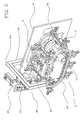
- the forming device 8 illustrated in detail in Figure 2 , is constituted by at least one support carriage 8a movable along a respective closed path P.
- the aforesaid path P has substantially elliptical shape and it is constituted by at least one active segment P' that is parallel and coincident with the vertical direction of advance A of the tubular wrapper 3, and by a passive segment P" opposite to the active segment P'.
- the device 8 has a plurality of carriages 8a actuated along the path P by respective actuating means 10 as shall be better described below.
- each carriage 8a is constituted by a pair of shoes 9 associated with a respective sealing base 11 at opposite ends 11a of the base 11 itself.
- each shoe 9 has a body 12 having substantially parallelepiped conformation in which is defined an inner surface 12a engaged to one of the ends 11a of the base 11 and an outer surface 12b opposite to the inner surface 12a.
- each body 12 has three castors 13a rotatable about respective axes, transverse to the development of the active segment P'.
- At least two of the three casters 13a are advantageously aligned to each other along the development of the path P, whilst the remaining castor is positioned below the first two.
- Each body 12 also has an upper portion 12c positioned above the base 11 in which is obtained a seat 12d adapted to house a contrasting element 14.
- each shoe 9 develops a base 11 having substantially parallelepiped conformation and developing along a respective longitudinal dimension, transverse to the aforementioned active segment P'.
- the sealing base 11 is adapted to be associated to a first lateral face 2a of the tubular wrapper 3, at a seal region Z of the wrapper 3 itself.
- seal region Z which is illustrated more clearly in Figures 11 through 13 , is constituted by a segment that is transverse to the longitudinal development of the tubular wrapper 3 whereat is joined a respective first lateral face 2a of the wrapper 3 itself with a second lateral face 2b opposite to the first one. In this way, between two seal regions Z is defined each individual container 2.
- the sealing base 11 has a first surface 15 able to be associated to the first lateral face 2a of the wrapper 3 and having longitudinal development corresponding to the seal region Z.
- the first surface 15 has respective sealing means, known in themselves and therefore not further described in detail.
- said sealing means can be constituted by an electrically heated lamina, a radio frequency emitter, or an ultrasound emitter.
- each sealing base 11 also has a second surface 16 opposite and parallel to the first surface 15. From the second surface 16 develop a first and a second projecting element 17, 18 respectively side by side to each other.
- the first projecting element 17 has an insertion pivot 17a which extends transversely to the planar surface of the second surface 16 below the base 11.
- the second projecting element 18 has an opening 18a obtained on the element 18 and oriented below the base 11.
- each body 12 of the respective shoes 9 has an upper portion 12c in which is obtained the seat 12d able to house the contrasting element 14.
- each shoe 9 has a contrasting element 14 movable between a first closed position in which it is approached to the base 11 and it abuts on the second lateral face 2b of the tubular wrapper 3 at the seal region Z, and a second position in which it is moved away from the base 11.
- each carriage 8a has two contrasting elements 14 associated at respective opposite ends 15a of the first surface 15 and each of which develops from the respective end 15a to a median portion of the first surface 15.
- the contrasting elements 14 of each carriage 8a are movable symmetrically between the first position in which they are side by die along a same longitudinal axis (see for example Figure 4 and 5 ) and the second position in which they face each other and are transverse to the longitudinal development of the first surface 15 (see for example Figure 3 ).
- each contrasting element 14 is constituted by a bar 19 having a respective active surface 19a able to abut on the first surface 15 of the base 11 in the first position of the contrasting element 14 itself.
- the active surface 19a of the bar 19 can have known sealing means, previously described in exemplifying fashion.
- the pressure exerted by the active surface 19a of the bar 19 and of the first surface 15 of the base 11 determines the pressing of the region Z of the tubular wrapper and the consequent sealing thereof.
- Each bar 19 also has an end portion 20 positioned at an end 11a of the base 11.
- the end portion 20 is inserted rotatably in the seat 12d obtained in the upper portion 12c of the respective body 12.
- end portion 20 is inserted in the upper portion 12c by means of a through pivot 20a, in such a way as to make the bar 19 rotatable about an axis that is perpendicular to the planar development of the first surface 15 of the base 11.
- each end portion 20 of the respective bar 19 develops a sliding element 13 positioned above the bar 19.
- This sliding element is constituted by a castor 13a rotatable about a respective axis, transverse to the longitudinal development of the respective bar 19.
- the means 10 for actuating the carriages 8a have at least one support guide 22 to guide the aforesaid carriages 8a along the closed path P.
- two support guides 22 are provided, parallel and distanced from each other, each of which is associated to each shoe 9 of each carriage 8a.
- each guide 22 is constituted by a rail 22a developing along a substantially elliptical path, corresponding to the development of the closed path P.
- each rail 22a is interposed between the sliding elements 13 in such a way that for each body 12 of the shoe 9 are positioned two castors 13a aligned to each other on an upper surface 22b of the rail 22a itself, and a third castor 13a on a lower surface 22c of the rail 22a.
- each rail 22a is constituted by a primary rectilinear portion 23 parallel to the direction of advance A of the tubular wrapper and corresponding to the aforesaid active segment P' of the closed path P. Moreover, each rail 22a has a secondary rectilinear portion 24 opposite and parallel to the primary rectilinear portion 23 and two arched junction portions 25 between the primary 23 and secondary 24 rectilinear portions.
- the secondary rectilinear portion 24 and the arched portions 25 constitute the aforesaid passive segment P" of the closed path P.
- Each guide 22 also has a side panel 26 positioned at the primary rectilinear path 23 and able to be associated to the bar 19 to actuate the contrasting elements 14 between the respective first and second position.
- each contrasting surface 27 has a first portion 27a parallel to the planar development of the first surface 15 of the base 11, and a second portion 27b consecutive to the first portion 27 and transverse to the planar development of the aforesaid first surface 15.
- each castor 13a associated to the respective end portion 20 of the corresponding bar 19 rotates on the contrasting surface 27 to rotate the bar 19 between the respective first and second position.
- the corresponding contrasting element 14 when each castor 13a associated to the respective bar 19 rotates on the first portion 27a of the contrasting surface 27, the corresponding contrasting element 14 is in the respective second position in which it is detached from the respective base 11.
- the castor 13a associated to the respective bar slides on the twisted portion rotating the contrasting element 14 about the pivot 20a, until the castor 13a is able to slide on the second portion 27b of the contrasting surface 27b, and the corresponding contrasting element 14 is positioned in the respective second position in which it is approached to the base 11.
- the actuating means 10 also have a first motor member 28 to actuate the carriages 8a along the active segment P' of the path P and a second motor member 29 to actuate the carriages 8a along the passive segment P" opposite to the aforesaid active segment P'.
- the first motor member 28 has a transport element 30 whose longitudinal development is parallel to the aforesaid active segment P' and associated to a motor 31. Both the motor 31 and the transport element 30 are interposed between the guides 22.
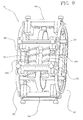
- the transport element 30 is constituted by an auger 32 rotatable about a respective longitudinal axis parallel to the aforesaid active segment P'.
- the auger 32 is constituted by a cylindrical body having an outer surface in which is obtained a helical cavity 32a.
- the insertion pivot 17a of the first projecting element 17 of the respective base 11 is inserted in the helical cavity 32a.
- the pivot 17a slides along the helical cavity 32a driving the base 11 and the respective pair of shoes 9 along the active segment P' corresponding to the longitudinal development of the auger 32.
- the auger 32 is set in rotation by means of the motor 31 through appropriate motion transmission members 31a, known and therefore not further described in detail.
- said transmission members 31 can be constituted by a pair of pulleys associated respectively to the drive shaft and to an end of the auger and associated to each other by means of a belt.
- the accompanying figures show an auger 32 having the respective helical cavity 32a with constant pitch, in order to maintain constant the actuation velocity of every carriage 8a along the active segment P' for the same angular velocity of the auger 32.
- a helical cavity 32a with non constant pitch may be provided to vary the actuation velocity of the carriages 8a.
- the helical cavity 32a may have a pitch (distance between a point of the cavity and the next symmetrical point) that is greater than the rest of the auger 32. In this way, when the carriage 8a slides along the greater pitch of the cavity 32a, it increases its speed because of the greater distance of the pitch.
- variations in the size of the pitch of the helical cavity 32a may be provided to quicken or slow the travel of the carriages 8a in the active segment P'.
- the first motor member 28 is constituted by a first and a second transport element 30 and 30' side by side to each other.
- the two transport elements 30 and 30' are respectively constituted by a first and a second auger 32 and 32' having longitudinal development, mutually parallel and parallel to the aforesaid active segment P'.
- the first and the second auger 32 and 32' have respectively the helical cavities 32a and 32a' with mutually different pitch, i.e. one of the cavities has a greater distance between one point and its next symmetrical point that the other helical cavity.
- the bases 11 belonging to respective carriages 8a have the first projecting element 17 positioned at the first or at the second auger 32 and 32'.
- the base 11 of a carriage 8a has the respective pivot 17a associated to the helical cavity 32a of the first auger 32 and the subsequent carriage 8a has the respective pivot 17a associated to the helical cavity 32a' of the second auger 32'.
- every carriage 8a can be actuated along the active segment P' at a different speed from the subsequent and from the previous carriage 8a.
- a first and a second auger 32 and 32' can be provided, with respective helical cavities having the same pitch.
- the two augers are actuated independently of each other and with different velocity to differentiate the velocity of advance of each carriage 8a.
- the second motor member 29 has at least two pulleys 33 positioned mutually side by side, each of which is positioned at an arched portion of junction 25.
- the pulleys 33 rotate about respective axes, mutually parallel and parallel to the planar development of the first surface 15 of each base 11.
- the pulleys 33 are respectively associated to a belt 34 positioned substantially along the aforesaid passive segment P" to transport each carriage 8a along the segment P" itself.
- the second motor member 29 also has at least one transmission roller 35 of the belt 34 positioned between two pulleys 33 to distance the belt 34 from the first motor member 28.
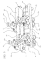
- the belt 34 has an inner surface 34a able to abut against the pulleys 33 and an outer surface 34b opposite to the inner surface 34a oriented towards the guides 22 and associated to the transmission roller 35. In this situation, as shown in Figure 8 , the belt 34 slides along a substantially two-lobed closed path defining the passive segment P".
- the belt 34 has a plurality of engagement pivots 36, mutually equidistant and extending from the outer surface 34b of the belt 34 (also visible in Figure 4 ).
- the transmission roller 35 which can abut against the outer surface 34b of the belt 34, has respective seats able to receive the engagement pivots 36 during the actuation of the belt 34.
- the engagement pivots 36 are advantageously shaped complementarily to the openings 18a obtained in the respective second projecting elements 18 of the bases 11 and able to be inserted into the openings 18a.
- the device 8 also has a plurality of walls 37 each of which is associated between two successive shoes 9 and adapted to be able to abut to a flank 2c of the tubular wrapper 3 transverse to the aforesaid first and second lateral face 2a, 2b.
- the walls 37 have substantially plate-like development and their planar development is transverse to the planar development of the first surface 15 of each base 11.
- a pair of walls 37 are provided, respectively associated between each carriage 8a and the adjacent carriage 8a.
- each wall 37 has a first end 37a pivotally engaged to a corresponding shoe 9 at the second surface 16 of the base 11, and a second end 37b opposite to the first.
- the second end 37b has a pivot, slidable within a slot whose development is parallel to the closed path P and which is obtained in a projection of the respective shoe 9. In this way, the adjacent carriages 8a can approach or move away from each other making the aforesaid pivot in the aforementioned slot.
- Each pair of walls 37 then abuts respective opposite flanks 2c of the tubular wrapper to give a substantially parallelepiped shape to each individual container 2 during the sealing of the region Z.
- the walls 37 are associated to the shoes 9, it should be noted that the walls 37 themselves are positioned abutting the opposite flanks 2c of the wrapper 3 only when the shoes are positioned along the active path P'.
- the forming device 8 lastly, has means 38 for cutting the tubular wrapper 3, which are operatively active at the seal region Z to obtain the individual containers.
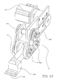
- the cutting means 38 have at least one separator device 39 illustrated in detail in Figure 10 and positioned downstream of the active segment P' relative to the direction of advance A of the tubular package 3.
- the separator device 39 is constituted by a support frame 40 secured to a load-bearing structure 41 of the forming device 8 (see Figure 2 ).
- the support frame 40 is constituted by an upright 40a developing above the tubular wrapper 3 transversely to the direction of advance A of the tubular wrapper 3.
- a motor 42 known and therefore not described further in detail, operatively associated to an arm 43, movable transversely to the direction of advance A between a first position in which it is moved away from the tubular wrapper 3 and a second position in which it is approached to the seal region Z of the wrapper 3 itself.
- the arm 43 has substantially longiform conformation in which a first end 43a is defined, positioned at the motor 42 and associated thereto by means of a transmission member 44.
- the transmission member 44 is constituted by a connecting rod-crank kinematic mechanism with three pulleys 44a set in rotation by the motor 42 by means of a belt 44b.
- the first end 43a is pivotally engaged to two of the three pulleys 44a (see Figure 10 ) at an off-centre point of the pulleys.
- the rotation of the pulleys 44a determines the rectilinear reciprocating movement of the entire arm 43 between the respective aforementioned first and second position.
- the arm 43 also has a second end 43b opposite to the first end 43a in which is obtained a housing seat of a blade 45 whose longitudinal development is parallel to the longitudinal development of the first surface 15 of each base 11.
- the blade 45 when the arm 43 is in the corresponding second position, the blade 45 is positioned above the seal region Z in order to cut it longitudinally. In this situation, after the transverse cut of the wrapper 3 the blade 45 abuts against the first surface 15 of the base 11 positioned below the blade 45 itself. It should be noted that, when the blade 45 approaches the wrapper 3 to cut the seal region Z, the contrasting elements 14 positioned on the respective base 11 are moved away from the first surface 15. In this way, the arm 43 can freely approach the tubular wrapper 3 without being hindered by the contrasting elements 14.
- the separator device 38 is positioned downstream of the guides 22 along the direction of advance A.
- two arms 43 and 43' are provided, facing each other and with each of them having the respective blade 45, 45'.
- tubular wrapper 3 is positioned between the two arms 43, 43' which are actuated in mutually independent fashion to move closer or farther away from each other.
- the respective blades 45 and 45' abut against each other in such a way as to cut the tubular wrapper 3 transversely at the respective seal region Z.
- the second end 43b' of the arm 43' has a contrasting support 46, adapted to abut against the blade 45 of the other arm 43.
- the contrasting support constitutes a fixed support of the blade 45 and it is advantageously provided with a recess (not shown in the figure) inside which is housed the blade 45.
- Figure 13 shows an additional embodiment variant of the separator device 38.
- only one arm 43 as described above is present and it is positioned at the active segment P' above the side panels 26.
- the bars 19 of the contrasting elements 14 have a through opening 47 which extends longitudinally along each bar 19.
- the through openings 47 of the bars 19 are mutually side by side and aligned in such a way as to define a single opening whose longitudinal development matches the longitudinal development of the seal region Z.
- the respective base 11 has a recess 48 obtained on the first surface 15 and developing along the longitudinal development of the surface 15.
- the recess 48 is placed at the openings 47 of the bars 19 when the bars 19 abut against the region Z to be sealed.
- the blade 45 passes through the openings 47 and cuts the region Z longitudinally until it inserts itself into the recess 48.
- the continuous strip 3a is fed from the respective reel 5 towards the forming member 6 of the tubular wrapper 3.
- the forming organ 6 folds at least one longitudinal edge of the continuous strip 3a on the other and longitudinally seals the region of superposition of the edges.
- tubular wrapper 3 is defined and fed along the vertical direction A by appropriate members, not described or illustrated in detail above because they are known.
- the tubular wrapper 3 fed vertically has a respective upper opening defined by the respective longitudinal edges, not yet sealed.
- the filling member 7 delivers the incoherent material inside the tubular wrapper 3 through the aforementioned upper opening. In this situation, the tubular wrapper 3 positioned vertically is filled only up to a certain height.
- the tubular wrapper 3 thus filled passes at the forming device 8 along the active segment P' of the closed path P.
- the sliding elements 13 of the respective shoes 9 slide along the primary rectilinear portions 23 of the respective guides 22 at the same velocity of advance as the tubular wrapper 3.
- each sliding element 13 positioned on the respective bar 19 slides on the first portion 27a of the contrasting surface and subsequently, following the twisted profile of the contrasting surface 27, it advances until reaching the second portion 27b.
- the sliding elements 13 positioned on the bars 19 move from a position in which they rotate on the first portion 27a about an axis that is parallel to the planar development of the first surface 15 of the base, to a position in which they rotate on the second portion 27b about an axis that is perpendicular to the planar development of the first surface 15.
- a spring 50 (shown in Figure 4 ) can be provided, positioned about the pivot 20a, which spring 50 determines the return of the contrasting element 14 in the respective second position.
- multiple carriages 8a are positioned simultaneously on the active segment P' in such a way that at least two successive carriages 8a are at the side panels 26.
- the tubular wrapper 2 can be sealed simultaneously in multiple parts or individually at different times.
- the flanks 2c of the wrapper 3 itself are deformed towards the exterior in such a way as to adhere to the walls 37.
- the containers 2 are formed with parallelepiped shape in which the flanks 2c constituted opposite lateral walls.
- each carriage 8a is associated in alternating fashion to one of the two augers 32, 32' .
- each pair of carriages 8a which are respectively associated to the first or to the second auger 32, 32' move with different velocities.
- the carriage 8a associated to the auger 32 having the helical cavity 32a with greater pitch moves faster than the carriage 8a that precedes it in such a way as to move the seal regions Z to each other and to define the squashing of the container 2.
- the carriage 8a When the contrasting element 14 return in the respective second position, the carriage 8a is positioned at the separator device 38. At this point the arm 43 is actuated towards the base 11 until the respective blade 45 does not abut against the seal region Z to cut it. As a result of the transverse cut of the tubular wrapper 3, the blade 45 bears on the first surface 15 of the base 11 and subsequently the arm 43 is moved away from the base 11.
- the containers 2 previously filled and formed are obtained as a result of the transverse cut.
- tubular wrapper 3 is made to advance sealed outside the guides 22 to allow the two arms 43 to approach each other and to cut the wrapper along the region Z to define the containers 2.
- the separator device 13 is positioned above the side panels 26 and the arm 43 approaches the wrapper 3 when the contrasting elements 14 are still pressing and sealing the wrapper 3.
- the blade 45 passes through the openings 47 obtained on the bars 19 to cut the region Z whilst it is sealed.
- the container 2 is already detached from the remained of the wrapper 3.
- the carriage 8a passes from the active segment P' to the passive segment P".
- the pivot 17a reaches the end of its travel in the helical cavity 32a and the base 11 is positioned at one of the two pulleys 33.
- One of the engagement pivots 36 positioned on the belt 34 is then inserted into the opening 18a driving the carriage 8a along the passive segment P" in the two arched portions 25 and in the secondary rectilinear portion to return the pair 9 to the active segment P'.
- the present invention solves the problems noted in the prior art and achieves the proposed objects.
- the forming device 8 allows to accomplish the sealing and the forming of the containers 2 during the travel of the tubular wrapper 3. Because of the movement along the active segment P' of the carriages 9 in synchrony with the advance of the wrapper 3 along the direction A, the bars 19 and the respective base 11 do not rub on the wrapper 3.
- the seals in the region Z and the forming of each individual container 2 are accomplished correctly.
- This advantage is due to the presence of a single pair of guides 22 adapted to support and guide the shoes 9.
- the forming device 8 in addition to having reduced size allows a marked reduction in construction and commercialisation costs and easy accessibility in case of failure.
Landscapes
- Engineering & Computer Science (AREA)
- Mechanical Engineering (AREA)
- Containers And Plastic Fillers For Packaging (AREA)
- Motorcycle And Bicycle Frame (AREA)
- Supplying Of Containers To The Packaging Station (AREA)
Claims (33)
- Dispositif pour produire des récipients (2) en continu à partir d'un système d'enveloppement tubulaire (3) alimenté dans une direction d'avancement sensiblement verticale (A), comprenant:- au moins un chariot support (8a) mobile le long d'un parcours fermé respectif (P) ayant au moins un segment actif (P') parallèle à ladite direction d'avancement (A);- une base de soudage (11) engagée audit chariot support (8a) et susceptible d'être associée à une première face latérale (2a) dudit système d'enveloppement tubulaire (3) en correspondance avec une zone de soudage (Z) dudit système d'enveloppement tubulaire (3);- des moyens (10) de mise en marche dudit chariot support (8a) le long dudit parcours (P); et- des moyens (38) de coupe dudit système d'enveloppement tubulaire (3) actifs de manière opérante en correspondance avec ladite zone de soudage (Z) pour obtenir lesdits récipients (2);caractérisé en ce qu'il comporte:- un élément de contraste (14) monté sur le chariot support (8a) et mobile entre une première position fermée à laquelle il est rapproché de ladite base (11) et vient buter contre une deuxième face latérale (2b) du système d'enveloppement tubulaire (3) opposée à la première face latérale (2a) en correspondance avec la zone de soudage (Z), et une deuxième position à laquelle il est mobile en éloignement de ladite base (11).
- Dispositif selon la revendication 1, caractérisé en ce que ladite base de soudage (11) a une première surface (15) dont le développement longitudinal est transversal à ladite direction d'avancement (A) et est munie des moyens respectifs pour souder ledit système d'enveloppement tubulaire (3).
- Dispositif selon la revendication 2, caractérisé en ce qu'il comprend deux éléments de contraste (14) associés en correspondance avec des extrémités opposées respectives (15a) de la première surface (15); lesdits éléments de contraste (14) se développant depuis lesdites extrémités opposées respectives (15a) jusqu'à une portion médiane de la première surface (15) et étant mobiles symétriquement entre la première position à laquelle ils sont alignés le long du même axe longitudinal et la deuxième position à laquelle ils sont réciproquement en vis-à-vis et sont transversaux au développement longitudinal de la première surface (15).
- Dispositif selon la revendication 3, caractérisé en ce que chaque élément de contraste (14) a une barre (19) présentant une surface active (19a) apte à venir buter contre ladite première surface (15) de la base (11) à la première position respective de l'élément de contraste (14); ladite barre (19) présentant en outre une portion d'extrémité (20) engagée à pivotement à une extrémité (11a) de la base (11) autour d'un axe respectif, transversal au développement de la première surface (15) de ladite base (11).
- Dispositif selon la revendication 1, caractérisé en ce qu'il comprend une pluralité de chariots support (8a), chacun desquels est associé à une base de soudage correspondante (11), à une extrémité respective (11a).
- Dispositif selon la revendication 5, caractérisé en ce que chaque chariot support (8a) comprend une paire de blocs de glissement (9), chaque paire de blocs de glissement (9) étant associée à une base de soudage correspondante (11), à des extrémités opposées (11a).
- Dispositif selon la revendication 6, caractérisé en ce que chaque bloc de glissement (9) a un corps (12) ayant une surface intérieure (12a) engagée à l'une desdites extrémités (11a) de la base (11), et au moins un élément coulissant (13) engagé de manière opérante aux moyens de mise en marche (10), et associé à une surface extérieure (12b) du corps (12) opposée à la surface intérieure (12a).
- Dispositif selon la revendication 7, caractérisé en ce que ledit corps (12) a une pluralité d'éléments coulissants (13) associés à la surface extérieure (12b) dudit corps (12).
- Dispositif selon la revendication 8, caractérisé en ce que lesdits éléments coulissants (13) comportent des roulettes (13a) pivotant autour d'un axe qui est parallèle au développement longitudinal de la première surface (15) de ladite base (11).
- Dispositif selon l'une quelconque des revendications 7 à 9, caractérisé en ce que chaque corps (12) des blocks de glissement respectifs (9) a également une portion supérieure (12c) positionnée au-dessus de ladite première surface (15) de la base (11); chaque portion d'extrémité (20) des barres respectives (19) étant insérée à pivotement dans un siège (24) obtenu dans la portion supérieure (12c) du corps respectif (12).
- Dispositif selon l'une quelconque des revendications 4 à 10, caractérisé en ce que chaque portion d'extrémité (20) de la barre respective (19) a un élément coulissant (13) positionné au-dessus de la barre (19) elle-même.
- Dispositif selon la revendication précédente, caractérisé en ce que ledit élément coulissant (13) associé à la portion d'extrémité (20) comprend au moins une roulette (13a) roulant autour d'un respectif axe, transversal au développement longitudinal de la première surface (15) de la base (11).
- Dispositif selon la revendication 1 ou 12, caractérisé en ce que lesdits moyens (10) de mise en marche dudit chariot support (8a) comprennent:- au moins un guidage de support (22) pour guider le chariot support (8a) le long dudit parcours fermé (P);- un premier organe moteur (28) pour mettre en marche le chariot support (8a) le long dudit segment actif (P'); et- un deuxième organe moteur (29) pour mettre en marche le chariot support (8a) le long d'un segment passif (P") opposé audit segment actif (P').
- Dispositif selon la revendication 13 quand elle dépend de la revendication 12, caractérisé en ce que lesdits moyens de mise en marche (10) comprennent deux guidages de support (22) parallèles et espacés l'un de l'autre, chacun desquels est associé à un bloc de glissement respectif (9) de chaque chariot support (a).
- Dispositif selon la revendication 14, caractérisé en ce que chaque guidage (22) a un rail (22a) ayant un développement elliptique et épousant le développement dudit parcours fermé (P), ledit rail (22a) étant interposé entre les éléments coulissants (13) positionnés sur la surface extérieure (12b) de chaque corps (12).
- Dispositif selon la revendication 15, caractérisé en ce que chaque rail (22a) a: une portion rectiligne primaire (23) parallèle à ladite direction d'avancement (A) du système d'enveloppement tubulaire (3) et correspondant audit segment actif (P') du parcours fermé (P); une portion rectiligne secondaire (24) opposée et parallèle à ladite portion rectiligne primaire (23); deux portions de jonction arquées (25) entre lesdites portion rectiligne primaire (23) et portion rectiligne secondaire (24); ladite portion rectiligne secondaire (24) et les portions arquées (25) correspondant audit segment passif (P") du parcours fermé (P).
- Dispositif selon la revendication 16, caractérisé en ce que chaque guidage de support (22) a un panneau latéral (26) positionné en correspondance avec ledit parcours rectiligne primaire (23) et apte à être associé aux éléments coulissants (13) positionnés sur les barres respectives (19) pour le mouvement des barres (19) entre les première et deuxième positions respectives.
- Dispositif selon la revendication 17, caractérisé en ce que chaque panneau latéral (26) a une surface de contraste gauchie (27) ayant une première portion (27a) parallèle au développement plan de la première surface (15) de la base (11) et une deuxième portion (27b) transversale au développement plan de la première surface (15); chaque roulette (13a) associée à la portion d'extrémité (20) de la barre respective (19) étant coulissante sur ladite surface de contraste (27).
- Dispositif selon la revendication 18, caractérisé en ce que dans la deuxième position de l'élément de contraste (14), la roulette respective (13a) positionnée sur la barre (19) est coulissante sur la première portion (27a) de la surface de contraste (27) et l'axe de rotation respectif est parallèle au développement de la première surface (15) de la base (11), et dans la première position de l'élément de contraste (14), la roulette respective (13a) est apte à coulisser sur la deuxième portion (27b) de la surface de contraste (27) et l'axe de rotation respectif est transversal au développement de la première surface (15) de la base (11).
- Dispositif selon la revendication 16, caractérisé en ce que ledit premier organe moteur (28) comporte un élément de transport (30) s'étendant parallèle audit segment actif (P') et positionné au-dessous de ladite portion rectiligne primaire (23); et un moteur (31) associé audit élément de transport (30).
- Dispositif selon la revendication précédente, caractérisé en ce que chaque base (11) comprend en outre un premier élément (17) faisant saillie d'une deuxième surface (16) de la base (11) opposée à ladite première surface (15) et ayant un pivot d'insertion (17a) s'étendant transversalement audit segment actif (P') au-dessous de la base (11) pour s'engager audit élément de transport (30).
- Dispositif selon la revendication 21, caractérisé en ce que ledit élément de transport (30) a une tarière (32) apte à tourner autour d'un axe longitudinal respectif correspondant audit segment actif (P'); ledit pivot d'insertion (17a) de chaque base (11) étant destiné à être inséré dans une cavité hélicoïdale (32a) obtenue sur la surface extérieure de ladite tarière (32) pour déplacer chaque bloc de glissement (9) le long de la portion rectiligne primaire (23).
- Dispositif selon la revendication 16, caractérisé en ce que ledit deuxième organe moteur (29) comprend: au moins deux poulies (33) aptes à tourner autour d'axes respectifs, parallèles entre eux et parallèles au développement de la première surface (15); et une courroie (34) associée auxdites poulies (33) et mobile le long dudit parcours passif (P").
- Dispositif selon la revendication 23, caractérisé en ce que chaque base (11) comprend en outre un deuxième élément (18) faisant saillie de ladite deuxième surface (16), disposé côte à côte par rapport audit premier élément faisant saillie (17) et susceptible d'engager ladite courroie (34).
- Dispositif selon la revendication 24, caractérisé en ce que ladite courroie (34) a une pluralité de pivots d'engagement (36) s'étendant à l'extérieur de la courroie (34) elle-même et espacés de la même distance les uns des autres; chaque pivot d'engagement (36) étant apte à être inséré dans une ouverture (18a) obtenue dans chaque deuxième élément faisant saillie (18) pour entraîner le chariot support respectif (8a) le long dudit segment passif (P").
- Dispositif selon l'une quelconque des revendications 23 à 25, caractérisé en ce que ledit deuxième organe moteur (29) comprend en outre au moins un rouleau de renvoi (35) de la courroie (34) positionné entre lesdites poulies (33) pour espacer la courroie (34) dudit premier organe moteur (28).
- Dispositif selon l'une quelconque des revendications 4 à 26, caractérisé en ce que chaque barre (19) comprend en outre des moyens de soudage positionnés sur la surface active (19a) de la barre elle-même.
- Dispositif selon l'une quelconque des revendications 2 à 27, caractérisé en ce que lesdits moyens de soudage comportent un générateur de chaleur.
- Dispositif selon l'une quelconque des revendications 6 à 28, caractérisé en ce qu'il comporte en outre une pluralité de parois (37), chacune associée à chaque bloc de glissement (9) et au bloc de glissement suivant respectif (9), ladite paroi (37) étant destinée à venir buter contre un flanc respectif (2c) du système d'enveloppement tubulaire (3) transversal aux première et deuxième faces latérales (2a, 2b).
- Dispositif selon la revendication 29, caractérisé en ce qu'il comprend une pluralité de paires de parois (37), chaque paire étant associée respectivement à un desdits chariots support (8a) et au chariot support (8a) suivant respectif et étant apte à venir buter contre les flancs opposés respectifs (2c) du système d'enveloppement tubulaire (3).
- Dispositif selon l'une quelconque des revendications précédentes, caractérisé en ce que lesdits moyens de coupe (38) ont au moins un dispositif séparateur (39) positionné à l'aval dudit segment actif (P') par rapport à la direction d'avancement (A) du système d'enveloppement tubulaire (3).
- Dispositif selon la revendication 31, caractérisé en ce que ledit dispositif séparateur (39) comporte:- un cadre support (40) fixé à une structure porteuse (41) du dispositif de formage (8);- un bras (43) mobile transversalement à ladite direction d'avancement (A) entre une première position à laquelle il est éloigné dudit système d'enveloppement tubulaire (3) et une deuxième position à laquelle il est rapproché de ladite zone de soudage (X) dudit système d'enveloppement tubulaire (3);- une lame (45) associée audit bras (43) et dont le développement est parallèle au développement de ladite première surface (15) de la base (11), ladite lame (45) étant apte à venir buter contre la première surface (15) dans la deuxième position dudit bras (43) pour couper ledit système d'enveloppement tubulaire (3); et- un moteur (42) fixé audit cadre (40) et associé de manière opérante audit bras (43).
- Unité pour conditionner les récipients (2) comprenant:- des moyens pour alimenter en continue une bande de papier (3a);- un organe de formage (6) pour unir les bords longitudinaux opposés de ladite bande continue (3a) et former ledit système d'enveloppement tubulaire (3); et- un organe de remplissage (7) positionné à l'aval dudit organe de formage (6) pour remplir d'un matériau incohérent ledit système d'enveloppement tubulaire;caractérisé en ce qu'il comporte en outre un dispositif (8) pour former des récipients (2) produits en continu à partir du système d'enveloppement tubulaire (3), suivant une ou plusieurs des revendications précédentes.
Applications Claiming Priority (2)
| Application Number | Priority Date | Filing Date | Title |
|---|---|---|---|
| IT000235A ITRM20040235A1 (it) | 2004-05-13 | 2004-05-13 | Dispositivo di formatura di contenitori prodotti in continuo da un incarto tubolare ed unita' confezionatrice di tali contenitori. |
| PCT/IT2005/000208 WO2005110856A1 (fr) | 2004-05-13 | 2005-04-13 | Dispositif pour produire des recipients en continu a partir d'un systeme d'enveloppement tubulaire, et unite pour conditionner lesdits recipients |
Publications (2)
| Publication Number | Publication Date |
|---|---|
| EP1755960A1 EP1755960A1 (fr) | 2007-02-28 |
| EP1755960B1 true EP1755960B1 (fr) | 2008-03-12 |
Family
ID=34965567
Family Applications (1)
| Application Number | Title | Priority Date | Filing Date |
|---|---|---|---|
| EP05734954A Expired - Lifetime EP1755960B1 (fr) | 2004-05-13 | 2005-04-13 | Dispositif pour produire des recipients en continu a partir d'un systeme d'enveloppement tubulaire, et unite pour conditionner lesdits recipients |
Country Status (8)
| Country | Link |
|---|---|
| US (1) | US7441390B2 (fr) |
| EP (1) | EP1755960B1 (fr) |
| CN (1) | CN100515867C (fr) |
| AT (1) | ATE388895T1 (fr) |
| DE (1) | DE602005005329T2 (fr) |
| ES (1) | ES2304011T3 (fr) |
| IT (1) | ITRM20040235A1 (fr) |
| WO (1) | WO2005110856A1 (fr) |
Families Citing this family (3)
| Publication number | Priority date | Publication date | Assignee | Title |
|---|---|---|---|---|
| US20100199614A1 (en) * | 2007-08-23 | 2010-08-12 | Tna Australia Pty Limited | Packaging machine for block bottom bags |
| ITUB20151128A1 (it) * | 2015-05-27 | 2016-11-27 | Marchesini Group Spa | Apparecchiatura per il trasferimento di articoli farmaceutici da una macchina contatrice all’interno di contenitori in avanzamento in continuo |
| EP3476751B1 (fr) * | 2017-10-31 | 2020-04-22 | Tetra Laval Holdings & Finance S.A. | Ensemble d'emballage destiné à former et sceller une pluralité de paquets contenant un produit alimentaire versable |
Family Cites Families (10)
| Publication number | Priority date | Publication date | Assignee | Title |
|---|---|---|---|---|
| US3320718A (en) * | 1964-06-01 | 1967-05-23 | Holstein & Kappert Maschf | Apparatus for filling and sealing containers |
| IT954476B (it) * | 1972-04-24 | 1973-08-30 | Dominici Antonio Flli | Procedimento e dispositivo per produrre contenitori d imballaggio riempiti e sigillati |
| US4109792A (en) * | 1973-04-04 | 1978-08-29 | The Dow Chemical Company | Method of packaging and product made thereby |
| US4305240A (en) * | 1979-07-05 | 1981-12-15 | Domain Industries | Package forming and sealing apparatus |
| US4483126A (en) * | 1982-02-17 | 1984-11-20 | The Woodman Company, Inc. | Adjustable drive mechanism |
| GB2162460B (en) * | 1984-07-31 | 1987-07-22 | Shibuya Kogyo Co Ltd | Apparatus for transversely sealing packages |
| DE3433802A1 (de) * | 1984-09-14 | 1986-03-27 | Tetra Pak Developpement S.A., Pully | Vorrichtung zum formen, verschweissen und foerdern von verpackungen |
| US5220771A (en) * | 1992-04-14 | 1993-06-22 | Milliken Research Corporation | Tetrahedron volume control |
| ES2232408T3 (es) * | 2000-02-15 | 2005-06-01 | TETRA LAVAL HOLDINGS & FINANCE S.A. | Unidad envasadora para producir en continuo envases sellados de productos alimenticios vertibles. |
| DE60105257T2 (de) * | 2001-02-23 | 2005-09-08 | Tetra Laval Holdings & Finance S.A. | Verpackungsmaschine und Verfahren zum Herstellen von versiegelten Verpackungen mit fliessfähigen Nahrungsmitteln |
-
2004
- 2004-05-13 IT IT000235A patent/ITRM20040235A1/it unknown
-
2005
- 2005-04-13 WO PCT/IT2005/000208 patent/WO2005110856A1/fr not_active Ceased
- 2005-04-13 AT AT05734954T patent/ATE388895T1/de not_active IP Right Cessation
- 2005-04-13 EP EP05734954A patent/EP1755960B1/fr not_active Expired - Lifetime
- 2005-04-13 ES ES05734954T patent/ES2304011T3/es not_active Expired - Lifetime
- 2005-04-13 CN CNB2005800211020A patent/CN100515867C/zh not_active Expired - Fee Related
- 2005-04-13 US US11/596,257 patent/US7441390B2/en not_active Expired - Fee Related
- 2005-04-13 DE DE602005005329T patent/DE602005005329T2/de not_active Expired - Lifetime
Also Published As
| Publication number | Publication date |
|---|---|
| DE602005005329T2 (de) | 2009-03-12 |
| ES2304011T3 (es) | 2008-09-01 |
| US7441390B2 (en) | 2008-10-28 |
| ITRM20040235A1 (it) | 2004-08-13 |
| US20080041024A1 (en) | 2008-02-21 |
| DE602005005329D1 (de) | 2008-04-24 |
| ATE388895T1 (de) | 2008-03-15 |
| CN100515867C (zh) | 2009-07-22 |
| WO2005110856A1 (fr) | 2005-11-24 |
| CN1972842A (zh) | 2007-05-30 |
| EP1755960A1 (fr) | 2007-02-28 |
Similar Documents
| Publication | Publication Date | Title |
|---|---|---|
| US6247293B1 (en) | Modular packaging machine with web tension control | |
| US6195967B1 (en) | Packaging machine having continuous and intermittent modes | |
| AU2004225982B2 (en) | High-speed continuous action form-fill-seal apparatus | |
| US6393809B2 (en) | Servo-controlled pouch making apparatus | |
| KR102299616B1 (ko) | 삼면 포장기 | |
| EP1755959B1 (fr) | Unite pour l'emballage de contenants et dispositif pour la formation de ces contenants produits en continu depuis un emballage tubulaire | |
| CN102639399B (zh) | 自动包装机 | |
| KR20140086964A (ko) | 관련 밀봉된 팩으로부터 쏟을 수 있는 식품 생산품의 접힌 패키지를 생산하기 위한 접는 유닛 | |
| KR20140086962A (ko) | 쏟을 수 있는 식품 생산품 패키지를 생산하기 위한 접는 유닛 및 방법 | |
| KR20140088083A (ko) | 쏟을 수 있는 식품 생산품 패키지를 생산하기 위한 접는 유닛용의 물품 핸들링 유닛을 위한 콘베이어 | |
| KR20140086963A (ko) | 쏟을 수 있는 식품 생산 포장 머신을 위한 접는 유닛 | |
| WO2004041645A1 (fr) | Unite de distribution de film pour systeme d'emballage par retractation et procede associe | |
| GB2298850A (en) | A stand-up pack | |
| CN113734522A (zh) | 一种中药颗粒袋装机 | |
| CN117615967A (zh) | 立式制袋填充包装机、装有内容物的薄膜包装袋的制造方法、装有内容物的薄膜包装袋 | |
| EP1755960B1 (fr) | Dispositif pour produire des recipients en continu a partir d'un systeme d'enveloppement tubulaire, et unite pour conditionner lesdits recipients | |
| EP1442980B1 (fr) | Appareil et procédé pour fabriquer des emballages refermables | |
| JP5126962B2 (ja) | 横型ピロー包装機 | |
| AU2005226944A1 (en) | Application of zipper lengths to a web | |
| JP6245689B2 (ja) | ガゼット形成装置及びエンドシール装置 | |
| CN217805575U (zh) | 一种中药颗粒袋装机 | |
| CN108438384B (zh) | 一种折叠包装件端部折片的方法 | |
| JP5490197B2 (ja) | 横型ピロー包装機 |
Legal Events
| Date | Code | Title | Description |
|---|---|---|---|
| PUAI | Public reference made under article 153(3) epc to a published international application that has entered the european phase |
Free format text: ORIGINAL CODE: 0009012 |
|
| 17P | Request for examination filed |
Effective date: 20061103 |
|
| AK | Designated contracting states |
Kind code of ref document: A1 Designated state(s): AT BE BG CH CY CZ DE DK EE ES FI FR GB GR HU IE IS IT LI LT LU MC NL PL PT RO SE SI SK TR |
|
| DAX | Request for extension of the european patent (deleted) | ||
| GRAP | Despatch of communication of intention to grant a patent |
Free format text: ORIGINAL CODE: EPIDOSNIGR1 |
|
| GRAS | Grant fee paid |
Free format text: ORIGINAL CODE: EPIDOSNIGR3 |
|
| GRAA | (expected) grant |
Free format text: ORIGINAL CODE: 0009210 |
|
| AK | Designated contracting states |
Kind code of ref document: B1 Designated state(s): AT BE BG CH CY CZ DE DK EE ES FI FR GB GR HU IE IS IT LI LT LU MC NL PL PT RO SE SI SK TR |
|
| REG | Reference to a national code |
Ref country code: GB Ref legal event code: FG4D |
|
| REG | Reference to a national code |
Ref country code: CH Ref legal event code: EP |
|
| REG | Reference to a national code |
Ref country code: IE Ref legal event code: FG4D |
|
| REF | Corresponds to: |
Ref document number: 602005005329 Country of ref document: DE Date of ref document: 20080424 Kind code of ref document: P |
|
| PG25 | Lapsed in a contracting state [announced via postgrant information from national office to epo] |
Ref country code: FI Free format text: LAPSE BECAUSE OF FAILURE TO SUBMIT A TRANSLATION OF THE DESCRIPTION OR TO PAY THE FEE WITHIN THE PRESCRIBED TIME-LIMIT Effective date: 20080312 Ref country code: LT Free format text: LAPSE BECAUSE OF FAILURE TO SUBMIT A TRANSLATION OF THE DESCRIPTION OR TO PAY THE FEE WITHIN THE PRESCRIBED TIME-LIMIT Effective date: 20080312 |
|
| PG25 | Lapsed in a contracting state [announced via postgrant information from national office to epo] |
Ref country code: AT Free format text: LAPSE BECAUSE OF FAILURE TO SUBMIT A TRANSLATION OF THE DESCRIPTION OR TO PAY THE FEE WITHIN THE PRESCRIBED TIME-LIMIT Effective date: 20080312 |
|
| NLV1 | Nl: lapsed or annulled due to failure to fulfill the requirements of art. 29p and 29m of the patents act | ||
| REG | Reference to a national code |
Ref country code: ES Ref legal event code: FG2A Ref document number: 2304011 Country of ref document: ES Kind code of ref document: T3 |
|
| PG25 | Lapsed in a contracting state [announced via postgrant information from national office to epo] |
Ref country code: BE Free format text: LAPSE BECAUSE OF FAILURE TO SUBMIT A TRANSLATION OF THE DESCRIPTION OR TO PAY THE FEE WITHIN THE PRESCRIBED TIME-LIMIT Effective date: 20080312 Ref country code: PL Free format text: LAPSE BECAUSE OF FAILURE TO SUBMIT A TRANSLATION OF THE DESCRIPTION OR TO PAY THE FEE WITHIN THE PRESCRIBED TIME-LIMIT Effective date: 20080312 Ref country code: SI Free format text: LAPSE BECAUSE OF FAILURE TO SUBMIT A TRANSLATION OF THE DESCRIPTION OR TO PAY THE FEE WITHIN THE PRESCRIBED TIME-LIMIT Effective date: 20080312 |
|
| PG25 | Lapsed in a contracting state [announced via postgrant information from national office to epo] |
Ref country code: SK Free format text: LAPSE BECAUSE OF FAILURE TO SUBMIT A TRANSLATION OF THE DESCRIPTION OR TO PAY THE FEE WITHIN THE PRESCRIBED TIME-LIMIT Effective date: 20080312 Ref country code: SE Free format text: LAPSE BECAUSE OF FAILURE TO SUBMIT A TRANSLATION OF THE DESCRIPTION OR TO PAY THE FEE WITHIN THE PRESCRIBED TIME-LIMIT Effective date: 20080612 Ref country code: PT Free format text: LAPSE BECAUSE OF FAILURE TO SUBMIT A TRANSLATION OF THE DESCRIPTION OR TO PAY THE FEE WITHIN THE PRESCRIBED TIME-LIMIT Effective date: 20080818 Ref country code: CZ Free format text: LAPSE BECAUSE OF FAILURE TO SUBMIT A TRANSLATION OF THE DESCRIPTION OR TO PAY THE FEE WITHIN THE PRESCRIBED TIME-LIMIT Effective date: 20080312 |
|
| PG25 | Lapsed in a contracting state [announced via postgrant information from national office to epo] |
Ref country code: RO Free format text: LAPSE BECAUSE OF FAILURE TO SUBMIT A TRANSLATION OF THE DESCRIPTION OR TO PAY THE FEE WITHIN THE PRESCRIBED TIME-LIMIT Effective date: 20080312 Ref country code: MC Free format text: LAPSE BECAUSE OF NON-PAYMENT OF DUE FEES Effective date: 20080430 Ref country code: NL Free format text: LAPSE BECAUSE OF FAILURE TO SUBMIT A TRANSLATION OF THE DESCRIPTION OR TO PAY THE FEE WITHIN THE PRESCRIBED TIME-LIMIT Effective date: 20080312 |
|
| ET | Fr: translation filed | ||
| PG25 | Lapsed in a contracting state [announced via postgrant information from national office to epo] |
Ref country code: IS Free format text: LAPSE BECAUSE OF FAILURE TO SUBMIT A TRANSLATION OF THE DESCRIPTION OR TO PAY THE FEE WITHIN THE PRESCRIBED TIME-LIMIT Effective date: 20080712 |
|
| PLBE | No opposition filed within time limit |
Free format text: ORIGINAL CODE: 0009261 |
|
| STAA | Information on the status of an ep patent application or granted ep patent |
Free format text: STATUS: NO OPPOSITION FILED WITHIN TIME LIMIT |
|
| PG25 | Lapsed in a contracting state [announced via postgrant information from national office to epo] |
Ref country code: DK Free format text: LAPSE BECAUSE OF FAILURE TO SUBMIT A TRANSLATION OF THE DESCRIPTION OR TO PAY THE FEE WITHIN THE PRESCRIBED TIME-LIMIT Effective date: 20080312 Ref country code: EE Free format text: LAPSE BECAUSE OF FAILURE TO SUBMIT A TRANSLATION OF THE DESCRIPTION OR TO PAY THE FEE WITHIN THE PRESCRIBED TIME-LIMIT Effective date: 20080312 |
|
| 26N | No opposition filed |
Effective date: 20081215 |
|
| PG25 | Lapsed in a contracting state [announced via postgrant information from national office to epo] |
Ref country code: BG Free format text: LAPSE BECAUSE OF FAILURE TO SUBMIT A TRANSLATION OF THE DESCRIPTION OR TO PAY THE FEE WITHIN THE PRESCRIBED TIME-LIMIT Effective date: 20080612 Ref country code: IE Free format text: LAPSE BECAUSE OF NON-PAYMENT OF DUE FEES Effective date: 20080414 |
|
| PG25 | Lapsed in a contracting state [announced via postgrant information from national office to epo] |
Ref country code: CY Free format text: LAPSE BECAUSE OF FAILURE TO SUBMIT A TRANSLATION OF THE DESCRIPTION OR TO PAY THE FEE WITHIN THE PRESCRIBED TIME-LIMIT Effective date: 20080312 |
|
| REG | Reference to a national code |
Ref country code: CH Ref legal event code: PL |
|
| PG25 | Lapsed in a contracting state [announced via postgrant information from national office to epo] |
Ref country code: LI Free format text: LAPSE BECAUSE OF NON-PAYMENT OF DUE FEES Effective date: 20090430 Ref country code: CH Free format text: LAPSE BECAUSE OF NON-PAYMENT OF DUE FEES Effective date: 20090430 |
|
| PGFP | Annual fee paid to national office [announced via postgrant information from national office to epo] |
Ref country code: GB Payment date: 20100330 Year of fee payment: 6 |
|
| PG25 | Lapsed in a contracting state [announced via postgrant information from national office to epo] |
Ref country code: HU Free format text: LAPSE BECAUSE OF FAILURE TO SUBMIT A TRANSLATION OF THE DESCRIPTION OR TO PAY THE FEE WITHIN THE PRESCRIBED TIME-LIMIT Effective date: 20080913 Ref country code: LU Free format text: LAPSE BECAUSE OF NON-PAYMENT OF DUE FEES Effective date: 20080413 |
|
| PGFP | Annual fee paid to national office [announced via postgrant information from national office to epo] |
Ref country code: ES Payment date: 20100510 Year of fee payment: 6 Ref country code: FR Payment date: 20100507 Year of fee payment: 6 |
|
| PG25 | Lapsed in a contracting state [announced via postgrant information from national office to epo] |
Ref country code: TR Free format text: LAPSE BECAUSE OF FAILURE TO SUBMIT A TRANSLATION OF THE DESCRIPTION OR TO PAY THE FEE WITHIN THE PRESCRIBED TIME-LIMIT Effective date: 20080312 |
|
| PGFP | Annual fee paid to national office [announced via postgrant information from national office to epo] |
Ref country code: IT Payment date: 20100427 Year of fee payment: 6 |
|
| PG25 | Lapsed in a contracting state [announced via postgrant information from national office to epo] |
Ref country code: GR Free format text: LAPSE BECAUSE OF FAILURE TO SUBMIT A TRANSLATION OF THE DESCRIPTION OR TO PAY THE FEE WITHIN THE PRESCRIBED TIME-LIMIT Effective date: 20080613 |
|
| PGFP | Annual fee paid to national office [announced via postgrant information from national office to epo] |
Ref country code: DE Payment date: 20100630 Year of fee payment: 6 |
|
| GBPC | Gb: european patent ceased through non-payment of renewal fee |
Effective date: 20110413 |
|
| REG | Reference to a national code |
Ref country code: FR Ref legal event code: ST Effective date: 20111230 |
|
| PG25 | Lapsed in a contracting state [announced via postgrant information from national office to epo] |
Ref country code: DE Free format text: LAPSE BECAUSE OF NON-PAYMENT OF DUE FEES Effective date: 20111101 Ref country code: FR Free format text: LAPSE BECAUSE OF NON-PAYMENT OF DUE FEES Effective date: 20110502 |
|
| REG | Reference to a national code |
Ref country code: DE Ref legal event code: R119 Ref document number: 602005005329 Country of ref document: DE Effective date: 20111101 |
|
| PG25 | Lapsed in a contracting state [announced via postgrant information from national office to epo] |
Ref country code: IT Free format text: LAPSE BECAUSE OF NON-PAYMENT OF DUE FEES Effective date: 20110413 Ref country code: GB Free format text: LAPSE BECAUSE OF NON-PAYMENT OF DUE FEES Effective date: 20110413 |
|
| REG | Reference to a national code |
Ref country code: ES Ref legal event code: FD2A Effective date: 20120604 |
|
| PG25 | Lapsed in a contracting state [announced via postgrant information from national office to epo] |
Ref country code: ES Free format text: LAPSE BECAUSE OF NON-PAYMENT OF DUE FEES Effective date: 20110414 |