EP1757729A2 - Agencement de presse - Google Patents
Agencement de presse Download PDFInfo
- Publication number
- EP1757729A2 EP1757729A2 EP06114449A EP06114449A EP1757729A2 EP 1757729 A2 EP1757729 A2 EP 1757729A2 EP 06114449 A EP06114449 A EP 06114449A EP 06114449 A EP06114449 A EP 06114449A EP 1757729 A2 EP1757729 A2 EP 1757729A2
- Authority
- EP
- European Patent Office
- Prior art keywords
- press
- arrangement according
- connecting elements
- press arrangement
- roll
- Prior art date
- Legal status (The legal status is an assumption and is not a legal conclusion. Google has not performed a legal analysis and makes no representation as to the accuracy of the status listed.)
- Withdrawn
Links
Images


Classifications
-
- D—TEXTILES; PAPER
- D21—PAPER-MAKING; PRODUCTION OF CELLULOSE
- D21F—PAPER-MAKING MACHINES; METHODS OF PRODUCING PAPER THEREON
- D21F3/00—Press section of machines for making continuous webs of paper
- D21F3/02—Wet presses
- D21F3/0209—Wet presses with extended press nip
- D21F3/0218—Shoe presses
-
- D—TEXTILES; PAPER
- D21—PAPER-MAKING; PRODUCTION OF CELLULOSE
- D21F—PAPER-MAKING MACHINES; METHODS OF PRODUCING PAPER THEREON
- D21F3/00—Press section of machines for making continuous webs of paper
- D21F3/02—Wet presses
- D21F3/04—Arrangements thereof
-
- D—TEXTILES; PAPER
- D21—PAPER-MAKING; PRODUCTION OF CELLULOSE
- D21G—CALENDERS; ACCESSORIES FOR PAPER-MAKING MACHINES
- D21G1/00—Calenders; Smoothing apparatus
- D21G1/006—Calenders; Smoothing apparatus with extended nips
-
- D—TEXTILES; PAPER
- D21—PAPER-MAKING; PRODUCTION OF CELLULOSE
- D21G—CALENDERS; ACCESSORIES FOR PAPER-MAKING MACHINES
- D21G1/00—Calenders; Smoothing apparatus
- D21G1/02—Rolls; Their bearings
- D21G1/0226—Bearings
Definitions
- the invention relates to a pressing arrangement for dewatering or smoothing a paper, cardboard, tissue or other fibrous web in a machine for producing and / or finishing the same with at least one, formed by a pressing and a counter-roller press nip, whose axes at least a roll end are mounted in separate support parts, wherein the press roll has a rotating roll shell, which is pressed via a contact element to the counter roll and the opposite support parts of at least one roll end via one or more connecting elements are releasably connected together.
- fasteners are for example from the EP 531491 known and take up skewing due to rolling deflections and thermal changes in length by elastic deformation.
- the object of the invention is therefore to prevent additional loading of the connecting elements.
- the object is achieved in that the connecting elements are articulated at least in one, preferably in both support parts.
- connecting elements are connected to the support parts such that at least the substantial, preferably the entire force flow flows between the support parts via the connecting elements.
- the joints should allow a change in position of the support parts to be joined to one another at least within the pressing plane. It is therefore advantageous if the connecting elements are articulated in two, preferably in all three spatial axes.
- At least one, preferably all connecting elements should be designed as tension rods.
- the tension rods can be installed and removed with relieved pressure elements of the press roll.
- the connecting elements should at least partially be arranged in recesses of the support parts.
- At least the rod ends should be arranged in recesses of the support parts.
- An advantageous embodiment of an articulated connection results when the condyle is formed by an eyelet which is mounted on a pin of the corresponding support member or connected via a bolt to the support member.
- the condyle is formed by a spherical or semi-spherical thickening, which is mounted in a joint shell.
- the joint shell allows the pivoting of the connecting element via a corresponding mobility of the thickening in the same.
- a partial, in particular hemispherical thickening in this case points in the direction of the connecting element.
- the joint shell for the thickening can be formed by the support part itself by a correspondingly shaped recess.
- joint shell is mounted removably in the support part. This allows the joint head to be installed and removed together with the joint shell.
- the manufacturing cost for the connecting elements decreases when at least one connecting element is integrally formed.
- the assembly of items may be preferred.
- a preferred embodiment of a multi-part connecting element results when the connecting element consists of a sleeve which is detachably connected at the ends, each with a condyle.
- the disassembly of the connecting elements can be substantially simplified if at least one, preferably the lower support part has a slope which extends only inclined in the axial direction and is suitable for receiving the, solved by this support part end of the connecting element.
- At least one connecting element should be present on both sides of the press plane at the corresponding roll end.
- the connecting elements extend parallel to the press plane.
- the connecting elements should be inclined in the direction of the press roller to the press plane.
- the invention allows the realization of a compact connection and the use of smaller press rolls.
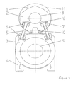
- the press arrangement has a press nip for dewatering or smoothing a fibrous web, in particular a paper web in a paper machine, which is formed by an overhead press roll 1 and a lower counter roll 3.
- the axes 8,9 of the rollers 1,3 are stored in separate support parts 2,4. While the axis 9 of the counter roll 3 co-rotates with this, the axis 8 of the press roll 1 is stationary.
- axis 8 and bearing and support part 2 of the press roll 1 can be made smaller than in the counter roll 3.
- the press roll 1 has a rotating roll shell 11, which is pressed by a stationary on the axis 8, stationary contact pressure element 10 to the counter roll 3.
- the pressing element 10 While in the case of dimensionally stable roll shells 11, the pressing element 10, as shown, has a convex pressing surface, this may be concave with flexible roll shell 11 to form an extended press nip.
- Prolonged press gaps allow an intensive yet volume-saving treatment of the fibrous web due to the longer residence time.
- the support members 2,4 are here leader side on both sides of the press plane 15 of the rollers 1.3 per a connecting element 5 in the form of a pull rod releasably connected together.
- connecting elements 5 are hinged on both sides in the support parts 2,4. This hinged connection frees the connecting elements 5 from bending stresses caused by rolling deflections and thermal elongation changes.
- the tension rods have rod ends at both ends.
- the connecting elements 5, in particular the rod ends are in recesses 16 of the support members 2,4 and are inserted axially into the support members 2,4. This happens with relaxed contact pressure element 10.
- connection is released by releasing the pressing element 10. Subsequently, the connecting elements 5 of the parts thereof can be removed.
- a spreading element which presses the support parts 2, 4 apart if required, can tension and relax the connection between the support parts 2, 4.
- the support part 2 of the press roll 1 is smaller than the roll shell 11, so that it can be easily pushed over the support part 2 in a necessary change after releasing the connection.
- the tension rods are made in one piece, the joint heads are formed at both ends of hemispherical thickenings 7, the ball surface facing the tension rod.
- These thickenings 7 are each mounted in a joint shell 6, which allows pivoting of the tension rod in all directions.
- the joint shell 6 is merged with the thickening 7 in a recess of the support part 2 and led out.
- the tension rods in Figure 2 are made of several parts. They are formed in the middle part of a sleeve 14 which can be connected to the rod ends present on both sides.
- the rod ends are designed here as eyelet 13, which is pushed onto a corresponding pin 12 or inserted pin of the support member 2,4.
- the individual parts of the connecting element 5 can be individually assembled and disassembled. But it is also possible when loosening the connection that in particular the eyelets 13 remain after the removal of the sleeve 14 on the pin 12.
- the sleeve is then simply connected to the eyelets 13 again.
- rod ends are in particular versions according to ISO 12240-4 and ISO 12240-1.
- the press arrangement becomes more compact by the optimization of the connecting elements 5.
- assembly and disassembly of the connecting elements 5 are substantially facilitated.
- the tension rods consist of a central portion 17 and the eyelets 13. They are connected by bolts 12 with the supports 2,4.
- the tension rods can be arranged perpendicular or inclined to the press plane 15.
- FIGS. 4a-d show a preferred sequence of disassembly of the connection.
- the bolts 12 are pulled (a) and the tie rods pushed upwards into a recess 18 of the support 2 (b). Thereafter, the tension rods are tilted forward (c) and taken over a slope 19 on the support 4 of the backing roll (d).
- Advantage of this embodiment is the simple removal of the tension rods without space to take side of the supports 2.4 to complete. This space can be used for other components around the roll package (eg rollers, scrapers, gutters).
Landscapes
- Paper (AREA)
Applications Claiming Priority (1)
| Application Number | Priority Date | Filing Date | Title |
|---|---|---|---|
| DE200510040722 DE102005040722A1 (de) | 2005-08-27 | 2005-08-27 | Pressanordnung |
Publications (2)
| Publication Number | Publication Date |
|---|---|
| EP1757729A2 true EP1757729A2 (fr) | 2007-02-28 |
| EP1757729A3 EP1757729A3 (fr) | 2007-04-18 |
Family
ID=37311914
Family Applications (1)
| Application Number | Title | Priority Date | Filing Date |
|---|---|---|---|
| EP06114449A Withdrawn EP1757729A3 (fr) | 2005-08-27 | 2006-05-24 | Agencement de presse |
Country Status (2)
| Country | Link |
|---|---|
| EP (1) | EP1757729A3 (fr) |
| DE (1) | DE102005040722A1 (fr) |
Cited By (2)
| Publication number | Priority date | Publication date | Assignee | Title |
|---|---|---|---|---|
| EP2151522A1 (fr) | 2008-08-04 | 2010-02-10 | Voith Patent GmbH | Agencement de presse pour machine à papier |
| CN102535226A (zh) * | 2010-11-26 | 2012-07-04 | 美卓造纸机械公司 | 连接装置 |
Families Citing this family (1)
| Publication number | Priority date | Publication date | Assignee | Title |
|---|---|---|---|---|
| DE102007005395A1 (de) | 2007-02-03 | 2008-08-07 | Voith Patent Gmbh | Pressanordnung |
Family Cites Families (3)
| Publication number | Priority date | Publication date | Assignee | Title |
|---|---|---|---|---|
| US4790908A (en) * | 1988-02-19 | 1988-12-13 | Beloit Corporation | Extended nip press belt guide and method |
| FI101633B (fi) * | 1994-02-04 | 1998-07-31 | Valmet Paper Machinery Inc | Pitkänippitelojen välinen kytkentärakenne ja menetelmä pitkänippiteloj en yhteenliittämisessä |
| AT412097B (de) * | 2002-10-17 | 2004-09-27 | Andritz Ag Maschf | Pressvorrichtung |
-
2005
- 2005-08-27 DE DE200510040722 patent/DE102005040722A1/de not_active Withdrawn
-
2006
- 2006-05-24 EP EP06114449A patent/EP1757729A3/fr not_active Withdrawn
Cited By (2)
| Publication number | Priority date | Publication date | Assignee | Title |
|---|---|---|---|---|
| EP2151522A1 (fr) | 2008-08-04 | 2010-02-10 | Voith Patent GmbH | Agencement de presse pour machine à papier |
| CN102535226A (zh) * | 2010-11-26 | 2012-07-04 | 美卓造纸机械公司 | 连接装置 |
Also Published As
| Publication number | Publication date |
|---|---|
| DE102005040722A1 (de) | 2007-03-01 |
| EP1757729A3 (fr) | 2007-04-18 |
Similar Documents
| Publication | Publication Date | Title |
|---|---|---|
| DE4217560C2 (de) | Walzenpresse | |
| EP0553462B1 (fr) | Liaisons de support entre deux rouleaux | |
| DE69416004T2 (de) | Kompakte rahmenanordnung für eine presse in einer maschine zur herstellung von papier oder karton | |
| DE102008016000B3 (de) | Walzenpresse | |
| DE4242022A1 (de) | Walzenpresse, insbesondere für die Papierindustrie | |
| EP1953295B1 (fr) | Agencement de presse | |
| EP1757729A2 (fr) | Agencement de presse | |
| AT400859B (de) | Walzenpresse | |
| AT412097B (de) | Pressvorrichtung | |
| EP2151522A1 (fr) | Agencement de presse pour machine à papier | |
| AT510755B1 (de) | Verbindungsanordnung | |
| EP1749926B1 (fr) | Dispositif de pressage | |
| EP1754821B1 (fr) | Dispositif de pressage | |
| AT410557B (de) | Wäschetrockner | |
| DE10156147A1 (de) | Zugriegel | |
| DE102008040965A1 (de) | Pressenanordnung für Papiermaschine | |
| DE102008054858A1 (de) | Pressanordnung für eine Papier-, Karton- oder Tissuemaschine | |
| AT14017U1 (de) | Vorrichtung zum Behandeln einer Faserbahn | |
| DE102006010350A1 (de) | Pressanordnung | |
| DE102008042130A1 (de) | Pressenanordnung für Papiermaschine | |
| AT404052B (de) | Scharniertopf | |
| DE112004000357T5 (de) | Verfahren und Vorrichtung zum Pressen einer Papierbahn | |
| DE102005038839A1 (de) | Pressanordnung | |
| DE9103795U1 (de) | Walzenpresse | |
| DE4413544A1 (de) | Preßvorrichtung |
Legal Events
| Date | Code | Title | Description |
|---|---|---|---|
| PUAI | Public reference made under article 153(3) epc to a published international application that has entered the european phase |
Free format text: ORIGINAL CODE: 0009012 |
|
| AK | Designated contracting states |
Kind code of ref document: A2 Designated state(s): AT BE BG CH CY CZ DE DK EE ES FI FR GB GR HU IE IS IT LI LT LU LV MC NL PL PT RO SE SI SK TR |
|
| AX | Request for extension of the european patent |
Extension state: AL BA HR MK YU |
|
| PUAL | Search report despatched |
Free format text: ORIGINAL CODE: 0009013 |
|
| AK | Designated contracting states |
Kind code of ref document: A3 Designated state(s): AT BE BG CH CY CZ DE DK EE ES FI FR GB GR HU IE IS IT LI LT LU LV MC NL PL PT RO SE SI SK TR |
|
| AX | Request for extension of the european patent |
Extension state: AL BA HR MK YU |
|
| 17P | Request for examination filed |
Effective date: 20071018 |
|
| AKX | Designation fees paid |
Designated state(s): AT BE BG CH CY CZ DE DK EE ES FI FR GB GR HU IE IS IT LI LT LU LV MC NL PL PT RO SE SI SK TR |
|
| RIN1 | Information on inventor provided before grant (corrected) |
Inventor name: GRABSCHEID, JOACHIM Inventor name: SCHMIDT, FRANK |
|
| STAA | Information on the status of an ep patent application or granted ep patent |
Free format text: STATUS: THE APPLICATION HAS BEEN WITHDRAWN |
|
| 17Q | First examination report despatched |
Effective date: 20140128 |
|
| 18W | Application withdrawn |
Effective date: 20140219 |