EP1757775A2 - Dispositif d'étanchéité pour une aube statorique variable - Google Patents
Dispositif d'étanchéité pour une aube statorique variable Download PDFInfo
- Publication number
- EP1757775A2 EP1757775A2 EP06013281A EP06013281A EP1757775A2 EP 1757775 A2 EP1757775 A2 EP 1757775A2 EP 06013281 A EP06013281 A EP 06013281A EP 06013281 A EP06013281 A EP 06013281A EP 1757775 A2 EP1757775 A2 EP 1757775A2
- Authority
- EP
- European Patent Office
- Prior art keywords
- machine axis
- radius
- rotor
- blade
- sphere
- Prior art date
- Legal status (The legal status is an assumption and is not a legal conclusion. Google has not performed a legal analysis and makes no representation as to the accuracy of the status listed.)
- Withdrawn
Links
- 238000007789 sealing Methods 0.000 title claims 2
- 238000002156 mixing Methods 0.000 claims 4
- 230000001419 dependent effect Effects 0.000 abstract description 2
- 230000002349 favourable effect Effects 0.000 description 6
- 230000006835 compression Effects 0.000 description 2
- 238000007906 compression Methods 0.000 description 2
- 230000015572 biosynthetic process Effects 0.000 description 1
- 238000006073 displacement reaction Methods 0.000 description 1
- 238000004519 manufacturing process Methods 0.000 description 1
- 230000000630 rising effect Effects 0.000 description 1
- 230000003068 static effect Effects 0.000 description 1
Images


Classifications
-
- F—MECHANICAL ENGINEERING; LIGHTING; HEATING; WEAPONS; BLASTING
- F01—MACHINES OR ENGINES IN GENERAL; ENGINE PLANTS IN GENERAL; STEAM ENGINES
- F01D—NON-POSITIVE DISPLACEMENT MACHINES OR ENGINES, e.g. STEAM TURBINES
- F01D17/00—Regulating or controlling by varying flow
- F01D17/10—Final actuators
- F01D17/12—Final actuators arranged in stator parts
- F01D17/14—Final actuators arranged in stator parts varying effective cross-sectional area of nozzles or guide conduits
- F01D17/16—Final actuators arranged in stator parts varying effective cross-sectional area of nozzles or guide conduits by means of nozzle vanes
- F01D17/162—Final actuators arranged in stator parts varying effective cross-sectional area of nozzles or guide conduits by means of nozzle vanes for axial flow, i.e. the vanes turning around axes which are essentially perpendicular to the rotor centre line
-
- F—MECHANICAL ENGINEERING; LIGHTING; HEATING; WEAPONS; BLASTING
- F04—POSITIVE - DISPLACEMENT MACHINES FOR LIQUIDS; PUMPS FOR LIQUIDS OR ELASTIC FLUIDS
- F04D—NON-POSITIVE-DISPLACEMENT PUMPS
- F04D29/00—Details, component parts, or accessories
- F04D29/40—Casings; Connections of working fluid
- F04D29/52—Casings; Connections of working fluid for axial pumps
- F04D29/54—Fluid-guiding means, e.g. diffusers
- F04D29/56—Fluid-guiding means, e.g. diffusers adjustable
- F04D29/563—Fluid-guiding means, e.g. diffusers adjustable specially adapted for elastic fluid pumps
-
- F—MECHANICAL ENGINEERING; LIGHTING; HEATING; WEAPONS; BLASTING
- F05—INDEXING SCHEMES RELATING TO ENGINES OR PUMPS IN VARIOUS SUBCLASSES OF CLASSES F01-F04
- F05D—INDEXING SCHEME FOR ASPECTS RELATING TO NON-POSITIVE-DISPLACEMENT MACHINES OR ENGINES, GAS-TURBINES OR JET-PROPULSION PLANTS
- F05D2250/00—Geometry
- F05D2250/20—Three-dimensional
- F05D2250/24—Three-dimensional ellipsoidal
- F05D2250/241—Three-dimensional ellipsoidal spherical
Definitions
- the invention relates to a gap control device for a gas turbine.
- the GB 2 235 730 A plans to perform the gap control on the housing via an adjustable outer shroud.
- the adjustment of the respective shroud segment is ensured by a mounted on the housing adjustment mechanism.
- the housing and the inner cover strip thus form the interfaces for the gas flow.
- the DE 42 137 16 A1 provides for the inner blade tip end of the adjustable stator blade and the opposite wall to form spherical, wherein the axis of the adjusting blades is perpendicular to the machine axis.
- the US 2002/0061249 A1 has local spherical recesses in the housing for each adjustment vane.
- the adjustable Statorschaufelachsen are there inclined to the machine axis to make the local corrugations aerodynamic.
- the compression of the air by the compressor rotor blades makes it necessary to make the gas channel more and more narrow, and thus the housing and / or to provide the inner cover tapes with a slope that can be very large, especially in the front steps.
- the front stator blades of the compressor are mostly adjustable. Due to this rotation, however, the gap between the housing and the variable stator blade changes as well as the gap between the inner shroud and the variable stator blade in conventional design. This gap formation proves to be disadvantageous and leads to aerodynamic losses.
- the invention has for its object to provide a gap control device of the type mentioned, which allows a simple design and simple, cost manufacturability minimizing the gap and minimizes aerodynamic losses while allowing an aerodynamic optimized design of the gas channel.
- the radial difference in height of the annular space is achieved by a spherical segment, wherein the spherical segment before / or. is cut behind the equator.
- the axis of rotation of the adjustable stator blades passes through the center of the sphere and is inclined at an angle ( ⁇ ) to the machine axis.
- the radius of the ball segment (R ball ) results from the radial distance of the blade tip at the intersection of the stator blade axis of rotation (R ma ) to the machine axis of rotation divided by sin ( ⁇ ).
- the angle ( ⁇ ) is inventively chosen so that the desired narrowing of the flow channel is formed.
- the angle of the axis of rotation is set so that the front edge of the radially outer end of the adjustable stator blade is covered by the rotary spindle.
- the gap between the trailing edge of the radially outer end of the stator blade and the housing can be minimized by the opposite inclination of the annular space in the axial direction and the inclination of the annular channel in the circumferential direction upon rotation of the adjustable stator blade.
- the spherically shaped region of the inner cover tape is followed by the gas channel geometry of the next rotor disk. The fact that the ball segment is not in the region of the equator of the ball, there is no turning point in the gas channel.
- the gas-flow area adjoining the blade row is formed substantially in the form of a spherical surface ring.
- this specially shaped gas-flowed region either on the housing, on the inner cover strip or on the rotor (one-sided mounting of the variable stator blade). The invention is thus applicable both to the radially inner region of the blade and to the radially outer region of the blade.
- the gas-circulated surface is inclined in the axial direction to the horizontal plane which encompasses the axis of rotation of the gas turbine.
- the spherical surface ring is thus not arranged in the equator of the ball, but laterally offset. Thus, a taper or narrowing of the flow cross-section of the compressor is possible. Since the axis of rotation of the adjustable stator blade extends through the ball center, thus the axis of rotation is inclined axially forward.
- the gap control device thus makes it possible to carry out an exact gap check.
- the gap remains constant over the entire adjustment range of the blade. This results in smaller gaps in the operating point of the compressor, whereby the efficiency is increased and the aerodynamic losses are reduced.
- the shape of a spherical surface can also be left slightly, so that deviates slightly from the ideal shape. This is covered by the invention.
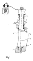
- the gap control device comprises a housing 1 of a gas turbine known from the prior art which is by means of a spindle 10 and a not further explained in detail, since known from the prior art adjusting a blade 2 is mounted. This is part of a compressor (compressor), as is also known from the prior art.
- FIG. 1 also shows the representation of a rotation axis 7 of the blade 2 and the gaps 8 or distances 8 which result between the ends of the blade 2.
- a gasumströmte surface 4 (see, for example, Fig. 2) of the housing 1 and / or the inner shroud 3 have an inclination to the engine rotational axis in the axial direction, so that narrows the gas channel during the compression of the air (see Fig. 1).
- the radially inner end of the adjustable stator blade and the gas-flowed surface (4) of the inner cover strip (3) is designed spherically.
- the radius of the ball (R ball) for intersecting the Statorschaufelspitze is inventively equal to the radial distance from the machine axis to Schaufelspizte at the node of Statorschaufelmosachse (R ma) divided by the sine of the inclination angle of Statorschauelwindachse 7 to the machine axis ( ⁇ ).
- the inclination of the axis of rotation 7 is inventively chosen so that the required height difference between the inlet and outlet edge of the axially cut inner shroud is formed (3).
- a spindle 9 of the blade 2 is blended according to the invention in a favorable development with the shape of a ball and thus is no longer in the gas stream.
- the region 6 of the rotor is also spherical in shape in accordance with the above-mentioned criteria, so that a uniform running gap is created with the spherical radially inner end of the stator blade.
- the region 6 corresponds at least to the maximum axial extent of the adjustable stator blade in its torsion region.
- Gasumströmten surfaces in a section transverse to the engine axis are annular or circular, as shown by the reference numeral 5 of FIG. 4.
- the axis of rotation 7 of the variable stator blade (blade 2) is arranged such that it lies perpendicular to the surface of the inner cover tape 3.
- the axis of rotation 7 of the blade 2 is thus, depending on the required inclination of the gasumströmten surface 4, axially inclined forward.
- the gasumströmte surface 4 is inventively designed so that it has the same curvature (reference numeral 6 in Fig. 3), as in the circumferential direction (reference numeral 5 of the circular shape of FIG. 4).
- the gasumströmte surface 4 thus forms a section of a ball or a spherical surface ring, as is clear from the representation of a ball 9 in Fig. 7.
- the blade 2 (stator blade) is arranged at a distance (gap 8) to the inner shroud 3 is formed so that the end of the blade 2 also forms part of a spherical surface.
- the distance or gap 8 is therefore only dependent from the manufacturing tolerances and thermal expansions. Incidentally, the distance remains constant with each rotation or adjustment of the blade 2, since two spherical surface parts are moved relative to each other.
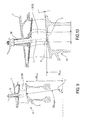
- the adjustable stator screen is mounted on one side (FIG. 12).
- the stator blade has no inner spindle.
- the radially inner region of the adjustable stator blade runs against the rotor drum 11.
- the opposite surfaces of the variable displacement vane (12) and the rotor (11) are spherical as described above.
Landscapes
- Engineering & Computer Science (AREA)
- Mechanical Engineering (AREA)
- General Engineering & Computer Science (AREA)
- Structures Of Non-Positive Displacement Pumps (AREA)
- Turbine Rotor Nozzle Sealing (AREA)
- Control Of Turbines (AREA)
Applications Claiming Priority (1)
| Application Number | Priority Date | Filing Date | Title |
|---|---|---|---|
| DE102005040574A DE102005040574A1 (de) | 2005-08-26 | 2005-08-26 | Spaltkontrollvorrichtung für eine Gasturbine |
Publications (2)
| Publication Number | Publication Date |
|---|---|
| EP1757775A2 true EP1757775A2 (fr) | 2007-02-28 |
| EP1757775A3 EP1757775A3 (fr) | 2008-07-23 |
Family
ID=36968166
Family Applications (1)
| Application Number | Title | Priority Date | Filing Date |
|---|---|---|---|
| EP06013281A Withdrawn EP1757775A3 (fr) | 2005-08-26 | 2006-06-27 | Dispositif d'étanchéité pour une aube statorique variable |
Country Status (3)
| Country | Link |
|---|---|
| US (1) | US20070160463A1 (fr) |
| EP (1) | EP1757775A3 (fr) |
| DE (1) | DE102005040574A1 (fr) |
Cited By (3)
| Publication number | Priority date | Publication date | Assignee | Title |
|---|---|---|---|---|
| EP2194235A1 (fr) * | 2008-12-05 | 2010-06-09 | Siemens Aktiengesellschaft | Composant de boîtier pour une turbomachine axiale doté d'un contrôle d'intervalle passif, turbine à gaz dotée du composant de boîtier et procédé destiné au rééquipement d'un composant de boîtier existant |
| EP2960438A1 (fr) * | 2014-06-26 | 2015-12-30 | MTU Aero Engines GmbH | Système d'aubes de guidage variables pour une turbine à gaz et turbine à gaz dotée d'un tel système |
| US10539024B2 (en) | 2013-03-10 | 2020-01-21 | Rolls-Royce Corporation | Variable pitch fan for a gas turbine engine |
Families Citing this family (12)
| Publication number | Priority date | Publication date | Assignee | Title |
|---|---|---|---|---|
| US9353643B2 (en) * | 2007-04-10 | 2016-05-31 | United Technologies Corporation | Variable stator vane assembly for a turbine engine |
| EP2405104A1 (fr) * | 2010-07-08 | 2012-01-11 | Siemens Aktiengesellschaft | Compresseur et moteur à turbine à gaz associé |
| DE102011119879A1 (de) * | 2011-12-01 | 2013-06-06 | Ihi Charging Systems International Gmbh | Fluidenergiemaschine, insbesondere für einen Abgasturbolader eines Kraftwagens |
| US9303524B2 (en) * | 2012-10-25 | 2016-04-05 | Solar Turbines Incorporated | Variable area turbine nozzle with a position selector |
| US20140119894A1 (en) * | 2012-10-25 | 2014-05-01 | Solar Turbines Incorporated | Variable area turbine nozzle |
| EP2961941B1 (fr) | 2013-02-26 | 2020-02-19 | Rolls-Royce Corporation | Appareils comprenant une aube statorique de turbine pivotable |
| DE102013218303A1 (de) * | 2013-09-12 | 2015-03-12 | Bosch Mahle Turbo Systems Gmbh & Co. Kg | Abgasturbolader mit Turbine |
| US9995166B2 (en) * | 2014-11-21 | 2018-06-12 | General Electric Company | Turbomachine including a vane and method of assembling such turbomachine |
| DE102014223975A1 (de) * | 2014-11-25 | 2016-05-25 | MTU Aero Engines AG | Leitschaufelkranz und Strömungsmaschine |
| EP3954882B1 (fr) * | 2016-03-30 | 2023-05-03 | Mitsubishi Heavy Industries Engine & Turbocharger, Ltd. | Turbocompresseur à géométrie variable |
| US20190301488A1 (en) * | 2018-04-03 | 2019-10-03 | Pratt & Whitney Canada Corp. | Gas path duct for a gas turbine engine |
| US12158078B2 (en) | 2023-03-14 | 2024-12-03 | Rtx Corporation | Compressor case with a cooling cavity |
Citations (3)
| Publication number | Priority date | Publication date | Assignee | Title |
|---|---|---|---|---|
| GB2235730A (en) | 1989-09-08 | 1991-03-13 | Gen Electric | Blade tip clearance control apparatus for a gas turbine engine |
| DE4213716A1 (de) | 1992-04-25 | 1993-10-28 | Asea Brown Boveri | Axialdurchströmte Turbine |
| US20020061249A1 (en) | 2000-09-18 | 2002-05-23 | Snecma Moteurs | Compressor stator having a constant clearance |
Family Cites Families (27)
| Publication number | Priority date | Publication date | Assignee | Title |
|---|---|---|---|---|
| BE514728A (fr) * | 1951-10-10 | |||
| US3089679A (en) * | 1960-06-06 | 1963-05-14 | Chrysler Corp | Gas turbine nozzle suspension and adjustment |
| US3542484A (en) * | 1968-08-19 | 1970-11-24 | Gen Motors Corp | Variable vanes |
| FR2030895A5 (fr) * | 1969-05-23 | 1970-11-13 | Motoren Turbinen Union | |
| FR2055780A1 (fr) * | 1969-08-14 | 1971-04-30 | Bennes Marrel | |
| GB1276720A (en) * | 1969-12-19 | 1972-06-07 | English Electric Co Ltd | Drives to adjustable stator blades for turbomachinery |
| US3719427A (en) * | 1971-03-22 | 1973-03-06 | Caterpillar Tractor Co | Variable area nozzle for turbines or compressors |
| US3999883A (en) * | 1975-07-02 | 1976-12-28 | General Motors Corporation | Variable turbomachine stator |
| US4013377A (en) * | 1975-10-08 | 1977-03-22 | Westinghouse Electric Corporation | Intermediate transition annulus for a two shaft gas turbine engine |
| DE2643607C2 (de) * | 1976-09-28 | 1978-05-18 | Motoren- Und Turbinen-Union Muenchen Gmbh, 8000 Muenchen | Vorrichtung zur Übertragung und Ermittlung des wahren Schaufelanstellwinkels verstellbarer Leitschaufeln einer Turbomaschine, insbesondere eines Gasturbinentriebwerks |
| US4150915A (en) * | 1976-12-23 | 1979-04-24 | Caterpillar Tractor Co. | Variable geometry turbine nozzle |
| US4278398A (en) * | 1978-12-04 | 1981-07-14 | General Electric Company | Apparatus for maintaining variable vane clearance |
| DE2931766C2 (de) * | 1979-08-04 | 1982-08-05 | MTU Motoren- und Turbinen-Union München GmbH, 8000 München | Dichtungseinrichtung für die freien Schaufelenden eines Verstell-Leitapparates einer Gasturbine |
| US4695220A (en) * | 1985-09-13 | 1987-09-22 | General Electric Company | Actuator for variable vanes |
| FR2599785B1 (fr) * | 1986-06-04 | 1990-10-12 | Snecma | Aubage directeur d'entree d'air a calage variable pour turboreacteur |
| FR2603340B1 (fr) * | 1986-09-03 | 1988-11-04 | Snecma | Turbomachine comportant un dispositif d'ajustement des jeux d'un joint a labyrinthe entre rotor et stator et de l'alignement de veine des gaz et methode d'application |
| FR2775731B1 (fr) * | 1998-03-05 | 2000-04-07 | Snecma | Etage circulaire d'aubes aux extremites interieures unies par un anneau de liaison |
| US6092984A (en) * | 1998-12-18 | 2000-07-25 | General Electric Company | System life for continuously operating engines |
| US6086327A (en) * | 1999-01-20 | 2000-07-11 | Mack Plastics Corporation | Bushing for a jet engine vane |
| DE10016745B4 (de) * | 2000-04-04 | 2005-05-19 | Man B & W Diesel Ag | Axialströmungsmaschine mit einem eine Reihe von verstellbaren Leitschaufeln umfassenden Leitapparat |
| US6413043B1 (en) * | 2000-11-09 | 2002-07-02 | General Electric Company | Inlet guide vane and shroud support contact |
| SE519353C2 (sv) * | 2000-11-15 | 2003-02-18 | Volvo Aero Corp | Stator till en gasturbin |
| ITTO20010445A1 (it) * | 2001-05-11 | 2002-11-11 | Fiatavio Spa | Statore di una turbina assiale a geometria variabile per applicazioniaeronautiche. |
| US7125222B2 (en) * | 2004-04-14 | 2006-10-24 | General Electric Company | Gas turbine engine variable vane assembly |
| US7360990B2 (en) * | 2004-10-13 | 2008-04-22 | General Electric Company | Methods and apparatus for assembling gas turbine engines |
| US7510369B2 (en) * | 2005-09-02 | 2009-03-31 | United Technologies Corporation | Sacrificial inner shroud liners for gas turbine engines |
| DE102005060699A1 (de) * | 2005-12-19 | 2007-06-21 | Rolls-Royce Deutschland Ltd & Co Kg | Strömungsarbeitsmaschine mit Verstellstator |
-
2005
- 2005-08-26 DE DE102005040574A patent/DE102005040574A1/de not_active Withdrawn
-
2006
- 2006-06-27 EP EP06013281A patent/EP1757775A3/fr not_active Withdrawn
- 2006-08-24 US US11/508,980 patent/US20070160463A1/en not_active Abandoned
Patent Citations (3)
| Publication number | Priority date | Publication date | Assignee | Title |
|---|---|---|---|---|
| GB2235730A (en) | 1989-09-08 | 1991-03-13 | Gen Electric | Blade tip clearance control apparatus for a gas turbine engine |
| DE4213716A1 (de) | 1992-04-25 | 1993-10-28 | Asea Brown Boveri | Axialdurchströmte Turbine |
| US20020061249A1 (en) | 2000-09-18 | 2002-05-23 | Snecma Moteurs | Compressor stator having a constant clearance |
Cited By (5)
| Publication number | Priority date | Publication date | Assignee | Title |
|---|---|---|---|---|
| EP2194235A1 (fr) * | 2008-12-05 | 2010-06-09 | Siemens Aktiengesellschaft | Composant de boîtier pour une turbomachine axiale doté d'un contrôle d'intervalle passif, turbine à gaz dotée du composant de boîtier et procédé destiné au rééquipement d'un composant de boîtier existant |
| US10539024B2 (en) | 2013-03-10 | 2020-01-21 | Rolls-Royce Corporation | Variable pitch fan for a gas turbine engine |
| EP2971596B1 (fr) * | 2013-03-10 | 2020-07-15 | Rolls-Royce Corporation | Moteur à turbine à gaz et procédé correspondant |
| EP2960438A1 (fr) * | 2014-06-26 | 2015-12-30 | MTU Aero Engines GmbH | Système d'aubes de guidage variables pour une turbine à gaz et turbine à gaz dotée d'un tel système |
| US10450877B2 (en) | 2014-06-26 | 2019-10-22 | MTU Aero Engines AG | Guide means for a gas turbine and gas turbine having such a guide means |
Also Published As
| Publication number | Publication date |
|---|---|
| DE102005040574A1 (de) | 2007-03-15 |
| EP1757775A3 (fr) | 2008-07-23 |
| US20070160463A1 (en) | 2007-07-12 |
Similar Documents
| Publication | Publication Date | Title |
|---|---|---|
| EP0598174B1 (fr) | Turbosoufflante pour une machine à combustion interne | |
| EP1757775A2 (fr) | Dispositif d'étanchéité pour une aube statorique variable | |
| DE69505074T2 (de) | Montageweise für einen Ring mit verstellbaren Leitschaufeln | |
| DE19518203C2 (de) | Einrichtung zur Aufnahme eines inneren Leitschaufelendes in einem Axialverdichter | |
| DE102005048814B4 (de) | Gasturbine und Baugruppe für eine Gasturbine | |
| DE102012202907B4 (de) | Abgasturbolader mit relativ zueinander verdrehbaren Leitgitterringen | |
| DE3516738A1 (de) | Stroemungsmaschine | |
| EP3269941B1 (fr) | Grille d'aube réglable pour turbomachines | |
| DE102008032661A1 (de) | Strömungsmaschine | |
| EP2478186B1 (fr) | Rotor de turbomachine | |
| EP1811134A1 (fr) | Dispositif de guidage réglable | |
| DE102018221812A1 (de) | Abgasturbine mit einer Abgasleiteinrichtung für einen Abgasturbolader und Abgasturbolader | |
| DE3833906A1 (de) | Leistungsregelbarer abgasturbolader | |
| EP0131719B1 (fr) | Dispositif variable de guidage | |
| EP3336313A1 (fr) | Ensemble d'aube mobile pour turbines d'une turbine turbine à gaz et procédé de fourniture d'air sceau dans un ensemble d'aube mobile pour turbines | |
| EP4130435A1 (fr) | Couronne d'aubes directrices pour une turbomachine, turbomachine et procédé de montage d'une couronne d'aubes directrices | |
| EP1706595B1 (fr) | Turbomachine comprenant un canal en spirale dans la partie mediane du carter | |
| DE112019007145T5 (de) | Aufladegerät mit variabler Leistung | |
| DE10257044B4 (de) | Gasturbine | |
| DE112017005661T5 (de) | Variable Düseneinheit und Turbolader | |
| EP3875736B1 (fr) | Dispositif d'étanchéité pour une turbomachine, bague de support pour un dispositif d'étanchéité et turbomachine | |
| EP1990545A1 (fr) | Roue de travail radiale (et variante), pale destinée à cette roue et ventilateur à canal doté de cette roue de travail | |
| DE69919534T2 (de) | Rotierende maschine | |
| EP3176385B1 (fr) | Boitier de stator pour une turbomachine et turbomachine comprenant un boitier de stator | |
| EP3298285B1 (fr) | Aube directrice pour un diffuseur aubagé d'un compresseur centrifuge |
Legal Events
| Date | Code | Title | Description |
|---|---|---|---|
| PUAI | Public reference made under article 153(3) epc to a published international application that has entered the european phase |
Free format text: ORIGINAL CODE: 0009012 |
|
| AK | Designated contracting states |
Kind code of ref document: A2 Designated state(s): AT BE BG CH CY CZ DE DK EE ES FI FR GB GR HU IE IS IT LI LT LU LV MC NL PL PT RO SE SI SK TR |
|
| AX | Request for extension of the european patent |
Extension state: AL BA HR MK YU |
|
| PUAL | Search report despatched |
Free format text: ORIGINAL CODE: 0009013 |
|
| AK | Designated contracting states |
Kind code of ref document: A3 Designated state(s): AT BE BG CH CY CZ DE DK EE ES FI FR GB GR HU IE IS IT LI LT LU LV MC NL PL PT RO SE SI SK TR |
|
| AX | Request for extension of the european patent |
Extension state: AL BA HR MK RS |
|
| STAA | Information on the status of an ep patent application or granted ep patent |
Free format text: STATUS: THE APPLICATION HAS BEEN WITHDRAWN |
|
| 18W | Application withdrawn |
Effective date: 20081202 |