EP1990545A1 - Roue de travail radiale (et variante), pale destinée à cette roue et ventilateur à canal doté de cette roue de travail - Google Patents
Roue de travail radiale (et variante), pale destinée à cette roue et ventilateur à canal doté de cette roue de travail Download PDFInfo
- Publication number
- EP1990545A1 EP1990545A1 EP07747807A EP07747807A EP1990545A1 EP 1990545 A1 EP1990545 A1 EP 1990545A1 EP 07747807 A EP07747807 A EP 07747807A EP 07747807 A EP07747807 A EP 07747807A EP 1990545 A1 EP1990545 A1 EP 1990545A1
- Authority
- EP
- European Patent Office
- Prior art keywords
- impeller
- slat
- axis
- rotation
- blades
- Prior art date
- Legal status (The legal status is an assumption and is not a legal conclusion. Google has not performed a legal analysis and makes no representation as to the accuracy of the status listed.)
- Withdrawn
Links
Images



Classifications
-
- F—MECHANICAL ENGINEERING; LIGHTING; HEATING; WEAPONS; BLASTING
- F04—POSITIVE - DISPLACEMENT MACHINES FOR LIQUIDS; PUMPS FOR LIQUIDS OR ELASTIC FLUIDS
- F04D—NON-POSITIVE-DISPLACEMENT PUMPS
- F04D29/00—Details, component parts, or accessories
- F04D29/26—Rotors specially for elastic fluids
- F04D29/28—Rotors specially for elastic fluids for centrifugal or helico-centrifugal pumps for radial-flow or helico-centrifugal pumps
- F04D29/281—Rotors specially for elastic fluids for centrifugal or helico-centrifugal pumps for radial-flow or helico-centrifugal pumps for fans or blowers
-
- F—MECHANICAL ENGINEERING; LIGHTING; HEATING; WEAPONS; BLASTING
- F04—POSITIVE - DISPLACEMENT MACHINES FOR LIQUIDS; PUMPS FOR LIQUIDS OR ELASTIC FLUIDS
- F04D—NON-POSITIVE-DISPLACEMENT PUMPS
- F04D17/00—Radial-flow pumps, e.g. centrifugal pumps; Helico-centrifugal pumps
- F04D17/08—Centrifugal pumps
- F04D17/10—Centrifugal pumps for compressing or evacuating
- F04D17/12—Multi-stage pumps
-
- F—MECHANICAL ENGINEERING; LIGHTING; HEATING; WEAPONS; BLASTING
- F04—POSITIVE - DISPLACEMENT MACHINES FOR LIQUIDS; PUMPS FOR LIQUIDS OR ELASTIC FLUIDS
- F04D—NON-POSITIVE-DISPLACEMENT PUMPS
- F04D29/00—Details, component parts, or accessories
- F04D29/26—Rotors specially for elastic fluids
- F04D29/28—Rotors specially for elastic fluids for centrifugal or helico-centrifugal pumps for radial-flow or helico-centrifugal pumps
- F04D29/30—Vanes
-
- F—MECHANICAL ENGINEERING; LIGHTING; HEATING; WEAPONS; BLASTING
- F04—POSITIVE - DISPLACEMENT MACHINES FOR LIQUIDS; PUMPS FOR LIQUIDS OR ELASTIC FLUIDS
- F04D—NON-POSITIVE-DISPLACEMENT PUMPS
- F04D29/00—Details, component parts, or accessories
- F04D29/66—Combating cavitation, whirls, noise, vibration or the like; Balancing
- F04D29/661—Combating cavitation, whirls, noise, vibration or the like; Balancing especially adapted for elastic fluid pumps
- F04D29/666—Combating cavitation, whirls, noise, vibration or the like; Balancing especially adapted for elastic fluid pumps by means of rotor construction or layout, e.g. unequal distribution of blades or vanes
Definitions
- the invention relates to a radial impeller with a main disc and a front disc and blades between the main disc and the front disc, wherein the blades are bent backwards.
- the invention relates to a blade to be used for the radial impeller and a duct fan in which the radial impeller is used with such blades.
- the utility model [2] describes an impeller, which is used in duct fans. In this case, the impeller ensures good properties for fans. These aerodynamic and acoustic properties are described, inter alia, in Catalog-2005 of the Limited Liability Company (OOO) "INNOVENT", Moscow, 2005, pp. 14-23, [3]. This makes it possible to compare the aerodynamic and acoustic properties of the impeller according to this application with the known impeller.
- the radial impeller according to the utility model of RF No. 22978 U, [2] is considered to be the closest prior art for the embodiments of the radial impeller.
- the patent RF No. 2287091 C1, IPC F04D 29/42, published on 10.11.2006, [4], is a duct fan.
- the duct fan includes a housing, an impeller with a main and a cover plate, an inlet collector, a drive of the impeller and an air duct. Between the main and the cover disc bent backwards blades are arranged.
- the air duct is formed between the housing walls.
- the air duct is designed with a cylindrical surface.
- an impeller is installed in the duct fan.
- This impeller uses the utility model [2].
- the reduction of the noise level emitted by the fan is one of the most important requirements of the consumers. For this reason, a further aerodynamic and acoustic perfection of the fan is required.
- the blades are formed with a slat, which is arranged closer to the axis of rotation of the impeller at the point where the main portion of the blade is adjacent to the surface of the front disk, that the intersection between the leading edge in the direction of rotation next blade and the front disc, the nose of the leading edge of the slat and the axis of rotation of the impeller lie on the same straight line within a projection plane which is perpendicular to the axis of rotation of the impeller and that the side edge of the slat is disposed at an acute angle to the leading edge of the slat.
- the technical result which is achieved in the duct fan in comparison to the closest prior art [4], consists in the noise reduction at the inlet and outlet of the fan while maintaining its pressure and flow behavior.
- the radial impeller according to the first embodiment includes, as well as the closest prior art [2], a main and a front disc and blades of the impeller.
- the blades are arranged between the discs and executed bent backwards.
- the blade is provided with an area (slat), which is arranged closer to the axis of rotation of the impeller, with respect to the point where the main body of the Shovel adjacent to the surface of the front disc.
- the intersection between the leading edge of the next (in the direction of rotation) blade and the front disc, the nose of the leading edge of the slat and the axis of rotation of the impeller lie on the same straight line within the projection surface on a plane.
- the plane is normal to the axis of rotation of the impeller.
- the side edge of the slat is arranged at an acute angle to the leading edge of the slat.
- the radial impeller according to the second embodiment includes, as well as the closest prior art, [2] a main and a front disk and blades of the impeller.
- the blades are arranged between the discs and executed bent backwards.
- each blade of the impeller is designed with a slat.
- the slat is disposed between the connection of the blade to the surface of the front disc and the axis of rotation of the impeller.
- the slat lies in the projection surface on the plane which is normal to the axis of rotation of the impeller.
- the axis of rotation of the impeller and the nose of the slat are connected by a straight line.
- This straight line does not extend beyond the sector which is formed (delimited) by half-lines.
- the half-lines lie within ⁇ 0.05 of the partial angle of the blades with respect to the straight line connecting the axis of rotation of the impeller and the terminal point of the leading edge of the next (in the direction of rotation) blade with the surface of the front disk.
- the radial impeller according to the first embodiment is characterized in that the leading edge of the vane of the blade is within a plane which is normal to the axis of rotation of the impeller.
- the radial impeller according to the first embodiment is characterized in that the leading edge of the vane blade is set at an angle of ⁇ 10 degrees to the plane normal to the rotation axis of the impeller.
- the radial impeller according to the first embodiment is characterized in that the leading edge of the slat of the blade of the impeller is designed curvilinear.
- the radial impeller according to the first embodiment is characterized in that the leading edge of the slat of the blade of the impeller is designed in the form of a circular arc.
- the radial impeller according to the first embodiment is characterized in that the portion of the blade adjacent to the front disk is made flat.
- the radial impeller according to the two embodiments is characterized in that the blade width at the outlet of the impeller at least 0.25 the diameter of a circle, which is rewritten from the blade ends of the impeller.
- the radial impeller according to the first embodiment is characterized in that blades 13 are installed in the impeller.
- the radial impeller according to the second embodiment is characterized in that the side edge of the slat is at an acute angle to the leading edge of the slat.
- the radial impeller according to the second embodiment is characterized in that the leading edge of the slat in cross-section, which is normal to the axis of rotation of the impeller, is designed circular arc.
- the radial impeller according to the second embodiment is characterized in that the diameter of the front disk is 1.1 to 1.2.
- the diameter of the main disc is 1.05 to 1.15 of the diameter of a circle circumscribed by the blade ends of the impeller.
- a non-divergent channel is formed in the meridian plane between the generatrices of the front and the main disc in the direction from the axis of rotation to the blade ends of the impeller.
- the radial impeller according to the second embodiment is characterized in that the radial impeller is formed with at least one ring which connects the side edges of the vanes of the blades.
- the blade of the radial impeller similar to the closest prior art [1], contains two regions. One area is intended for connection to the front pane. The second area is arranged closer to the axis of rotation of the impeller (the slat). It has a front and a side edge. The leading edge of the slat is curvilinear. On the contrary to the next booth However, the technique [1], the leading edge of the slat is arranged in the plane which is normal to the axis of rotation of the impeller. The side edge is at an acute angle to the front edge. The side edge is curvilinear with a local radius which increases as the distance from the leading edge increases.
- the blade is characterized by the fact that the front and the side edges of the slat are connected by a circular arc.
- the blade is characterized in that the blade area, which is intended for connection to the front disk, is made flat.
- the air duct is formed between the housing walls and designed with a cylindrical surface.
- the cross-sectional area of the air passage between the housing walls exceeds the area of the circle circumscribed by the blade ends of the impeller by at least 2.4 times.
- each blade of the impeller is designed with a slat.
- the slat is disposed between the connection of the blade to the surface of the front disc and the axis of rotation of the impeller. In this case, the slat lies in the projection surface on the plane which is normal to the axis of rotation of the impeller.
- the axis of rotation of the impeller and the leading edge nose of the slat are connected by a straight line.
- the half-lines lie within ⁇ 0.05 of the pitch angle of the blades with respect to the straight line connecting the axis of rotation of the rotor and the point of attachment of the leading edge of the next blade (in the direction of rotation) to the front disk.
- the duct fan is characterized in that at least two impellers are installed in its housing. Between the adjacent wheels, a partition wall is arranged. The ratio of the cross-sectional area of each air channel between the housing walls to the surface of the circle, which is circumscribed by the blade ends of the impeller installed in the corresponding air duct, is at least 2.4.
- the duct fan is equipped with at least one vortex damper.
- the vortex damper lies in the space between the front disc and the inlet collector.
- the cross-sectional contour of the air channel between the housing walls in the cross-sectional area which is arranged normal to the axis of rotation of the impeller, designed in the form of a rectangle.
- the distance between the long sides of the channel exceeds the diameter of the impeller by at least 1.01 times.
- At least one vortex damper is installed in the space between the disc and the inlet collector along the short side.
- the cross-sectional contour of the air channel between the housing walls in the cross-sectional area which is arranged normal to the axis of rotation of the impeller, can also be performed circular or oval-shaped.
- the duct fan is characterized in that the housing wall is formed with an outer and an inner lining.
- the interior lining is perforated. Between the panels a sound absorbing material is used. Of the Sound-absorbing material is separated from the perforated inner lining by an airtight film.
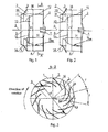
- the radial impeller according to the first and second embodiments, as in Fig. 1 and 2 shown, includes a front disk 1 and a main disk 2 and the blades arranged therebetween 3.
- the impeller is provided with a hub 4.
- the hub 4 is used for connection to the power distribution.
- the inlet 5 of the air flow into the impeller lies in the plane which is formed by the front edges of the front disk 1.
- the outlet 6 of the air flow from the impeller is located between the outer edges of the front disk 1 and the main disk 2 (FIG. Fig. 1 and 2 ).
- the blades 3 are bent backwards ( Fig. 3 ).
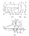
- Each of the blades 3 includes a main portion 7 and a portion which is subsequently slat 10 (FIG. Fig. 1, 2 and 4 ) is called.
- the leading edge 8 ( Fig. 4 ) of the main area 7 adjoins the front pane 1.
- the slat 10 is arranged closer to the axis of rotation 9 of the impeller.
- the main area 7 and the slat 10 can be made inseparable, z. B., from a metal sheet ( Fig. 3 and 5 ) or as an aerodynamic profile (not shown).
- the main area 7 and the slat 10 may also be assembled ( Fig.
- the leading edge 11 of the slat 10 may be within an angular range ⁇ 10 degrees to the plane which is normal to the axis of rotation 9 of the impeller.
- the side edge 12 is at an acute angle to the front edge 11 (FIG. Fig. 4 ).
- the front and side edges are connected by a smooth curve, e.g. B., by means of a circular arc. Thus, they form a nose 13 on the slat 10.
- the leading edge 11 of the slat 10 is executed in the projection on the plane which is normal to the axis of rotation 9 of the impeller, curvilinear, z. B., circular arc ( Fig. 3 . 5 and 6 ).
- the side edge 12 can be made curvilinear, z. Example, with a local radius R SK , which increases depending on the increasing distance from the leading edge 11 ( Fig. 1, 2 and 4 ).
- the axis of rotation 9 of the impeller, the nose 13 of the slat 10 of the blade 3 and the connection point 14 of the leading edge 8 to the front disc 1 of the leading edge 8 of the next (in the direction of rotation) blade 3A ( Fig. 3 ) in the impeller according to the first embodiment lie on a straight line in the projection on a plane which is normal to the axis of rotation 9 of the impeller.
- the execution of the impeller with the mentioned deviation ⁇ t of the nose 13 of the slat 10 from the straight line, which runs over the axis of rotation 9 of the impeller and the connection point 14 of the leading edge 8 of the next (in the direction of rotation) blade 3A with the front disk 1, is the second embodiment of the impeller.
- Said straight line passes over a point on the nose 13.
- this point is determined in both embodiments of the impeller by pulling on the nose 13 of the slat 10 a tangent which is parallel to the axis 9 of the impeller.
- the side edges 12 of the slat 10 by means of a ring 15 (FIG. Fig. 1 and 2 ) connected. Similar rings may be used at the ends 16 of the blades 3 and in addition to the already installed ring 15 at the side edges 12 of the slat 10 (not shown).
- the blade 3 can be designed so that the surface of the slat 10 has a smooth contour, in detail cylindrical ( Fig. 3 . 5 and 6 ) or with the twisting of the slat 10 and the main portion 7 of the blade 3 (not shown).
- the radial impeller ( Fig. 1, 2 and 3 ) 13 blades 3.
- the width H of the blades 3 coincides with the distance between the front disc 1 and the main disc 2 at its intersection with the ends 16 of the blades 3 at the outlet 6 from the impeller together. This width H is 0.25 to 0.37 of the diameter of the impeller D.
- the main portion 7 of the blades 3 is made flat.
- the adjacent thereto vanes 10 is designed in a circular arc in cross section, which is normal to the axis of rotation 9 of the impeller.
- the leading edge 11 and the side edge 12 of the slat 10 are connected together in a circle.
- the side edge 12 is designed with a local radius R SK .
- the local radius R SK is at least 0.5D adjacent to the leading edge 11.
- the side edge 12 is parallel to the axis of rotation 9 of the impeller (ie, infinity) adjacent to the main disk 2 (FIG. Fig. 1 ).
- the axis of rotation 9 of the impeller and the nose 13 of the slat 10 are connected by a straight line. This line is located in the projection on the plane which is normal to the axis of rotation 9 of the impeller. This straight line does not extend beyond the sector which is formed (delimited) by half-lines.
- this straight line lies on the straight line which the axis of rotation 9 of the impeller and the intersection of the leading edge 14 of the next (in the direction of rotation) blade 3A with the front disk 1 ( Fig. 7 ) connects, ( Fig. 3 and 7 ).
- the front disk 1 and the main disk 2 can be made with an enlarged diameter.
- the diameter is in each case (1.1 ... 1.2) D and (1.05 ... 1.15) D.
- the main area 7 of the blades 3 is made flat with a rectilinear side edge 8.
- the blades 3 of the impeller are designed with a flat main region 7 and the slat 10.
- the slat 10 has a cylindrical surface.
- the front edge 8 of the main body 7 of the blade 3 is rectilinear.
- the nose 13 connects the leading edge 11 and the side edge 12 of the slat.
- the nose 13 is executed circular arc.
- the leading edge 11 of the slat 10 in the projection onto the plane, which is normal to the axis of rotation 9 of the impeller, is circular arc-shaped.
- the side edge 12 is designed curvilinear. In this case, it has a local radius R SK , which increases depending on the increasing distance from the front edge 11 ( Fig. 1, 2 and 4 ).
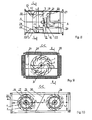
- the duct fan includes a housing 17, a motor 18, an impeller 19 and an inlet header 20 (FIGS. Fig. 8 ).
- the housing 17 is designed with a channel 21.
- the channel 21 is bounded by walls 22.
- the channel 21 has any surface shape. In the preferred embodiment, however, the surface is cylindrical.
- the contour of the housing base is a rectangle ( Fig. 9 ), a trapeze ( Fig. 10 ), a square, a circle, an oval, an ellipse and on (not shown).
- the impeller 19 includes the front disk 1 and the main disk 2 and the blades 3 interposed therebetween.
- the blades 3 are bent rearwardly with respect to the direction of rotation of the impeller ( Fig. 3 ).
- Each blade 3 is provided with a slat 10.
- the slat 10 is located between the connection of the blade 3 to the surface of the front disk 1 and the axis of rotation 9 of the impeller ( Fig. 1 and 2 ).
- the axis of rotation 9 of the impeller 19 and the nose 13 of the slat 10 are connected by a straight line.
- the straight line is in the projection on the plane which is perpendicular to the axis of rotation 9 of the impeller 19. This straight line does not extend beyond the sector which is formed (delimited) by half-lines.
- the impeller 19 is kinematically connected to a motor 18.
- the connection is z. B. by means of a hub 4.
- the hub 4 is fixed to the main disc 2 and directly with the shaft 23 of the motor 18 (FIG. Fig. 8 ) coupled.
- the connection is also made by means of a belt drive or similar gear (not shown).
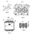
- the inlet collector 20 is arranged on the front side of the housing 17 and executed with a curvilinear profile in its diametrical cross-section. In this case, a converging gap 24 between the surfaces of the cover plate 1 and the inlet header 20 (FIG. Fig. 8 and 11 ) educated.
- the axis of rotation 9 of the impeller 19 and the axis of symmetry of the inlet collector 20 are coaxial.
- the housing 17 is designed so that in the plane which to the axis of symmetry of the inlet collector 20 to the installation point of the impeller 19 (FIG. Fig.
- the walls 22 of the housing 17 may be designed as plates 26.
- the plates 26 contain thermal insulation material and / or sound-absorbing material ( Fig. 9 and 13 ).
- the wall panels 26 are formed with the outer panel 27 and the inner panel 28.
- the inner lining 28 is perforated with holes 29 (FIG. Fig. 13 ). Between the panels 27 and 28 Schallschluckstoff 30 is laid.
- the sound-absorbing substance 30 is separated from the perforated inner lining 28 by means of an airtight foil 31 (FIG. Fig. 14 ) separated.
- the duct fan is equipped with a vortex damper.
- the vortex damper is z. B. executed in the form of at least one plate 32.
- the plate 32 has a flat or curvilinear surface.
- the plate 32 is located in the swirling space 33.
- the swirling space 33 is located between the intake manifold 20 and the front disk 1 of the impeller 19 (FIG. Fig. 8 ) educated.
- the plate 32 of the vortex damper is installed in the channel 21 of the housing 17 in front of the converging gap 24. If the cross-section of the channel is rectangular, the plates 32 of the vortex damper lie along the short side of the channel 21 (FIG. Fig. 8 ).
- At least one additional impeller 34 may be installed in the housing 17 of the duct fan. Coaxial with the impeller 34 is the inlet header 20 (FIG. Fig. 10 and 12 ) and at least one vortex damper.
- the vortex damper is designed in the form of a plate 32.
- the vortex damper is in one of the vortex spaces 33 (FIG. Fig. 8 ) built-in.
- the length B of the shorter side of at least one channel 21 exceeds the diameter D of the corresponding impeller 19 or 34 (and if the impeller with enlarged discs, Fig. 2 at least 1.01 times: B / D ⁇ 1.01.
- the reduction of the gap between the wall of the channel 21 and the impeller 19 (or the disks 1 and 2) is limited by the possible procedural errors in the manufacture of the fan.
- the adjacent wheels 19 and 34 can be separated from each other by means of a partition 35.
- the partition wall 35 can be located both between the long sides A (FIG. Fig. 10 ) as well as between the short sides B ( Fig. 12 ) 22 of the channel 21 are arranged.
- the partition wall 35 is located, as a rule, normal to the plane which, via the axis of rotation 9 of the wheels 19 and 34 (FIGS. Fig. 12 ) runs.
- the partition wall 35 is inclined or normal to the surface of the wall of the channel 21 (FIG. Fig. 10 ). In the inclined position, the partition wall 35 is connected to the walls 22 of the housing 17. The connection is made in such a way that the distance of the edge of the partition wall 35 from the bucket 3 is greater than the distance from the run-off blade 3 of the corresponding impeller 19 or 34 (FIG. Fig. 10 ).
- the duct fan includes connection flanges 25, the housing 17 and the plates 32 of the vortex damper.
- the connecting flanges 25 are inserted at the end faces of the housing 17.
- the plates 32 of the Vorbeldämpfers are arranged in the vortex space 33 in front of the converging gap 24.
- the walls 22 of the housing 17 are in the form of plates 26 with thermal insulation material and Schallschluckstoff 30 executed.
- the channel has a rectangular cross section.
- the diameters D of the wheels 19 and 34 are made similar and equipped with its own motor 18 and the coaxial inlet collector 20.
- Each of the blades 3 is designed with a slat 10.
- the slat 10 is located between the connection of the blade 3 to the surface of the front disk 1 and the axis of rotation 9.
- the axis of rotation 9 of the impeller 19 and the nose 13 of the slat 10 are connected by a straight line.
- This straight line lies in the projection on the plane which is normal to the axis of rotation 9 of the impeller 19. This straight line does not extend beyond the sector which is formed (delimited) by the half-line.
- the impeller constitutes the parting surface.
- the reduction of the aerodynamic noise behind the impeller does not lead to any noticeable consequences for the noise in front of the impeller and vice versa.
- the side edge 12 and the leading edge 11 of the vane 10 of the blade 3 which is not adjacent to the front disk 1, generate sound waves.
- a fairly remote location in front of the wheel is z. B. on the continuation of the axis 9 of the impeller.
- the noise at this point is determined by summing the sound pressure signals from all points of the leading edges 11 and the side edges 12 of all slats 10 of the blades 3.
- the leading edge 11 of the vane 10 of the blade 3 must have such a shape and spatial orientation that the instantaneous sum of all sound pressure signals from all points of the leading edge 11 tends to zero.
- the side edge 12 of the slat 10 flows around a downdraft, shadowed by the front edge 11 and affects only slightly the generation of Umströmungsgehoffsche.
- This condition can be satisfied when the leading edge 11 of the slat 10 of the blade 3 is in a plane normal to the rotation axis 9 of the impeller (hereinafter called "front edge perpendicularity condition") and when the rotation axis 9 of the impeller Nose 13 of the slat 10 of the blade 3 and the intersection point 14 lie on a straight line.
- the straight line lies in the projection on the plane which is normal to the axis of rotation 9 of the impeller.
- the point of intersection 14 is the point of intersection (connection point) of the next (in the direction of rotation) blade 3A with the front disk 1 (FIG. Fig. 3 and 7 ).
- the intersection point 14 corresponds to the partial angle t between the blades at the inlet 5 into the impeller (hereinafter called “partial angle condition between the blades").
- the aerodynamic and acoustic behavior of the impeller can only be researched if the impeller is installed in the housing. Therefore, the experimental verification of the influence of the conditions of rectangularity of the leading edge and the pitch angle between the blades on the acoustic behavior was carried out by placing the registered impeller in the housing.
- the aerodynamic and acoustic properties of a series-produced duct fan [4] with the mass-produced impeller [2] (fan no. 1 at characteristic curves Fig. 18 to 21 ) and the registered impeller and fan (fan no. 4 on characteristic curves Fig. 18 to 21 ) compared.
- the influence of the side edge 12 on the noise generation at any point, which is located before the inlet 5 in the impeller, must be excluded.
- the side edge 12 of the slat 10 must be "in the shade" of the leading edge 11. This can be ensured by arranging the side edge 12 at an acute angle (below 90 degrees) to the leading edge 11. In this case, the leading edge over the line, which the nose 13 of the slat 10 and the connection point 14 of the side edge 12 to the front plate 2 ( Fig. 3 ), does not result.
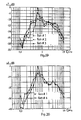
- ⁇ L F (f).
- the difference module of the sound pressure level ⁇ L varies only slightly. In this case, the maximum in the region of the arrangement of the axis of rotation 9, the nose 13 of the slat and the connection point 14 is achieved.
- the axis of rotation 9, the nose 13 and the connection point 14 lie on a straight line, which corresponds to the embodiment of the impeller according to the first embodiment. This is an important factor because it extends the range of geometrical parameters of the impeller and defines the second embodiment of the impeller.
- the ring 15 connects the side edges 12 of the slat 10.
- the leading edge 11 of the slat 10 of the blade 3 must be performed curvilinear.
- the leading edge 11 z. B. arcuate or in the form of an ellipse and other smooth curves.
- a stepless entry into the intermediate vane space must be ensured. This can be achieved if the airflow lines tangentially adjoin the side edge 12 of the slat 10 of the blade 3. For a part of the side edge 12, this is ensured by the fact that the side edge 12 is designed with an increasing local radius R SK .
- the local radius R SK increases depending on the distance from the leading edge 11 into the infinity.
- the side edge 12 lies on a straight line, which runs parallel to the axis of rotation 9 of the impeller.
- a stepless expansion according to the current with optimum delay must be ensured.
- the 4-channel fans have impellers of the same diameter and with the same number of blades 3.
- the blades 3 are arranged in housings of the same dimensions.
- the channel 21 has a square cross-section.
- the housings are designed with dimensions specified in the catalog [3] for a ventilator of the type «UNIVENT-2-2».
- the series-produced fan was tested according to the «UNIVENT-2-2» type.
- This fan has an impeller with flat blades 3.
- the blades 3 are designed in accordance with the utility model [2] and the invention [4].
- the blades have no slat and have an inner side edge 36, the concurrent with the axis of rotation 9 of the impeller ( Fig. 4 ).
- the blades fulfill the condition of the angular distance t between the blades.
- the blades have a main region 8 and the slat 10 with leading edge 11.
- the leading edge 11 lies in the plane which is normal to the axis of rotation 9 of the impeller.
- the slat 10 also has a side edge 37, which to the axis of rotation 9 of the impeller ( Fig. 3 ) is parallel.
- Such embodiment of the blades 3 is described in the invention [1].
- the blade 3 is made composite ( Fig. 5 ).
- the side edge 38 of the slat 10 is rectilinear and adjoins the leading edge 11 at an acute angle.
- the side edge 38 is with the front edge 11 linked according to the radius ( Fig. 3 ) and is connected to the main disk 2.
- the 4th fan incorporates an impeller according to this invention.
- the blades 3 ( Fig. 5 ) are set in accordance with the condition of the partial angle between the blades.
- the blade 3 is designed with a slat 10.
- the leading edge 11 of the slat 10 is normal to the axis of rotation 9 of the impeller.
- the side edge 12 of the slat 10 of the blade 3 is designed with an increasing local radius R SK .
- the local radius R SK becomes larger the greater the distance from the leading edge (FIG. Fig. 1 and 3 ).
- the aerodynamic properties of the impellers with blades 3 without slats were compared below with blades 3 with slats 10.
- the blades 3 with slat 10 have a bevelled rectilinear side edge 38 (fan No. 3) and a side edge 12 with a variable radius R SK (fan No. 4).
- fans # 3 and # 4 ensure a higher static pressure compared to series # 1 fan.
- the fan no. 4 ensures a higher static pressure within the entire power range compared to fan no. 3.
- the side edge 12 of the slat 10 of the blade 3 is performed curvilinear. It is provided with the local radius, which increases depending on the distance from the front edge of the slat 10. Thus, this embodiment of the side edge 12 ensures an improvement in the aerodynamic behavior of the impeller.
- the registered duct fan is equipped with plates 32 of vortex damper.
- the plates 32 are installed in the swirling space 33, as in Fig. 20 displayed.
- the equipment of the duct fan with plates 32 leads to the increase of the static pressure at the same power factor.
- the equipment of the registered duct fan with an additional impeller 34 as in Fig. 21 shown, doubles the power at the same static pressure.
- the presence of a partition 35 between the wheels 19 and 34 at low and medium performance indicators causes the increase in power safely.
- This makes it possible to use the duct fan with two and more impellers instead of the duct fan with one impeller.
- This fact creates extensive possibilities in connection with the reduction of one of the dimensions of the housing of the duct fan.
- the installation of the partition 35 increases the strength of the housing 17 of the fan. This is particularly important in the small distance between the ends 16 of the blades 3 and the walls 22 of the housing 17 of the fan.
- the radial impellers shown in the description of this invention may be incorporated in duct and centrifugal fans and compressors.
- the registered blades can be used in the running wheels according to this invention.
- the duct fans with one, two and more impellers can be used in ventilation and air conditioning systems for residential, production buildings and Operating equipment and gas transport in different systems are used.
Landscapes
- Engineering & Computer Science (AREA)
- Mechanical Engineering (AREA)
- General Engineering & Computer Science (AREA)
- Structures Of Non-Positive Displacement Pumps (AREA)
Applications Claiming Priority (3)
| Application Number | Priority Date | Filing Date | Title |
|---|---|---|---|
| RU2006103511/06A RU2310774C1 (ru) | 2006-02-08 | 2006-02-08 | Радиальное рабочее колесо и лопатка для него |
| RU2007102815/06A RU2330189C1 (ru) | 2007-01-25 | 2007-01-25 | Радиальное рабочее колесо и канальный вентилятор с этим рабочим колесом |
| PCT/RU2007/000061 WO2007091923A1 (fr) | 2006-02-08 | 2007-02-07 | Roue de travail radiale (et variante), pale destinée à cette roue et ventilateur à canal doté de cette roue de travail |
Publications (2)
| Publication Number | Publication Date |
|---|---|
| EP1990545A1 true EP1990545A1 (fr) | 2008-11-12 |
| EP1990545A4 EP1990545A4 (fr) | 2014-03-12 |
Family
ID=38345427
Family Applications (1)
| Application Number | Title | Priority Date | Filing Date |
|---|---|---|---|
| EP07747807.1A Withdrawn EP1990545A4 (fr) | 2006-02-08 | 2007-02-07 | Roue de travail radiale (et variante), pale destinée à cette roue et ventilateur à canal doté de cette roue de travail |
Country Status (2)
| Country | Link |
|---|---|
| EP (1) | EP1990545A4 (fr) |
| WO (1) | WO2007091923A1 (fr) |
Cited By (5)
| Publication number | Priority date | Publication date | Assignee | Title |
|---|---|---|---|---|
| EP2357365A3 (fr) * | 2010-02-01 | 2012-04-25 | Brink Climate Systems B.V. | Système de mouvement d'air |
| CN103032374A (zh) * | 2013-01-17 | 2013-04-10 | 福州福发发电设备有限公司 | 中频发电机风扇及其生产工艺 |
| FR2984971A1 (fr) * | 2011-12-21 | 2013-06-28 | Seb Sa | Roue de ventilation centrifuge, ventilateur correspondant et appareil de cuisson incluant un tel ventilateur |
| CN103486078A (zh) * | 2013-10-23 | 2014-01-01 | 株洲联诚集团有限责任公司 | 一种双向扩压的离心通风机 |
| EP2206929A4 (fr) * | 2007-09-26 | 2014-06-18 | Balakirev Evgeni Borisovitch | Unité de ventilateurs possédant une roue libre radiale principale |
Families Citing this family (1)
| Publication number | Priority date | Publication date | Assignee | Title |
|---|---|---|---|---|
| CN104132004B (zh) * | 2014-08-04 | 2016-08-24 | 绿田机械股份有限公司 | 一种柴油机用的冷却风扇 |
Family Cites Families (4)
| Publication number | Priority date | Publication date | Assignee | Title |
|---|---|---|---|---|
| US3260443A (en) * | 1964-01-13 | 1966-07-12 | R W Kimbell | Blower |
| IT1318801B1 (it) * | 2000-08-31 | 2003-09-10 | Nuovo Pignone Spa | Dispositivo per la regolazione continua della portata di gas trattatada un compressore alternativo. |
| RU22978U1 (ru) * | 2001-11-13 | 2002-05-10 | Караджи Вячеслав Георгиевич | Рабочее колесо радиального вентилятора |
| RU45482U1 (ru) * | 2004-07-16 | 2005-05-10 | Караджи Вячеслав Георгиевич | Канальный вентилятор |
-
2007
- 2007-02-07 WO PCT/RU2007/000061 patent/WO2007091923A1/fr not_active Ceased
- 2007-02-07 EP EP07747807.1A patent/EP1990545A4/fr not_active Withdrawn
Cited By (6)
| Publication number | Priority date | Publication date | Assignee | Title |
|---|---|---|---|---|
| EP2206929A4 (fr) * | 2007-09-26 | 2014-06-18 | Balakirev Evgeni Borisovitch | Unité de ventilateurs possédant une roue libre radiale principale |
| EP2357365A3 (fr) * | 2010-02-01 | 2012-04-25 | Brink Climate Systems B.V. | Système de mouvement d'air |
| FR2984971A1 (fr) * | 2011-12-21 | 2013-06-28 | Seb Sa | Roue de ventilation centrifuge, ventilateur correspondant et appareil de cuisson incluant un tel ventilateur |
| CN103032374A (zh) * | 2013-01-17 | 2013-04-10 | 福州福发发电设备有限公司 | 中频发电机风扇及其生产工艺 |
| CN103032374B (zh) * | 2013-01-17 | 2015-06-24 | 福州福发发电设备有限公司 | 中频发电机风扇及其生产工艺 |
| CN103486078A (zh) * | 2013-10-23 | 2014-01-01 | 株洲联诚集团有限责任公司 | 一种双向扩压的离心通风机 |
Also Published As
| Publication number | Publication date |
|---|---|
| WO2007091923A1 (fr) | 2007-08-16 |
| EP1990545A4 (fr) | 2014-03-12 |
Similar Documents
| Publication | Publication Date | Title |
|---|---|---|
| EP1608875B1 (fr) | Roue de soufflante radiale, unite de soufflante, et dispositif de soufflante radiale | |
| DE3882463T2 (de) | Diffusor für Zentrifugalverdichter. | |
| EP2655891B1 (fr) | Diffuseur de ventilateur avec entrée circulaire et sortie sans symétrie de révolution | |
| EP3184826B1 (fr) | Dispositif de ventilateur | |
| EP2669474A1 (fr) | Canal de passage pour une turbomachine et turbomachine | |
| EP1990545A1 (fr) | Roue de travail radiale (et variante), pale destinée à cette roue et ventilateur à canal doté de cette roue de travail | |
| CH669431A5 (fr) | ||
| EP1447568B1 (fr) | Roues et diffuseurs pour ventilateurs et compresseurs | |
| EP2333348B1 (fr) | Boîtier de ventilateur radial | |
| EP3999717B1 (fr) | Élément intermédiaire pour une connexion aube-disque de rotor pour le rotor d'une turbomachine, rotor pour une turbomachine et turbomachine | |
| WO2020099034A1 (fr) | Ventilateur diagonal compact équipé d'un dispositif directeur de sortie | |
| DE8505239U1 (de) | Schalldämpfer mit Vorleitschaufeln an der Ansaugseite des Verdichters eines Abgasturboladers | |
| DE3401210C2 (fr) | ||
| EP1637697B1 (fr) | Passage d'une machine à écoulement avec intervalle axial ayant une concentration inférieure à 1 | |
| EP1757775A2 (fr) | Dispositif d'étanchéité pour une aube statorique variable | |
| DE20303443U1 (de) | Radiallüfterrad | |
| EP2626644B1 (fr) | Composant d'aération comprenant un boîtier en forme de canal doté de parois de boîtier agencées de manière périphérique | |
| EP2206929A1 (fr) | Unité de ventilateurs possédant une roue libre radiale principale | |
| EP0145857B1 (fr) | Ventilateur axial sans aubes de guidage particulièrement pour échangeurs de chaleur | |
| EP1998052A2 (fr) | Ventilateur axial doté d'un appareil directeur connecté en aval | |
| EP0143235B2 (fr) | Ventilateur axial sans couronne de guidage particulièrement pour la ventilation d'échangeurs de chaleur | |
| EP2811170A1 (fr) | Ventilateur radial | |
| DE102017119213A1 (de) | Strömungsgitter zur Reduktion der Wirbelgröße in einer Fluidströmung | |
| DE3343752A1 (de) | Offenes laufrad fuer stroemungsmaschinen | |
| EP4577727A1 (fr) | Ventilateur à jet |
Legal Events
| Date | Code | Title | Description |
|---|---|---|---|
| PUAI | Public reference made under article 153(3) epc to a published international application that has entered the european phase |
Free format text: ORIGINAL CODE: 0009012 |
|
| 17P | Request for examination filed |
Effective date: 20080908 |
|
| AK | Designated contracting states |
Kind code of ref document: A1 Designated state(s): AT BE BG CH CY CZ DE DK EE ES FI FR GB GR HU IE IS IT LI LT LU LV MC NL PL PT RO SE SI SK TR |
|
| DAX | Request for extension of the european patent (deleted) | ||
| A4 | Supplementary search report drawn up and despatched |
Effective date: 20140210 |
|
| RIC1 | Information provided on ipc code assigned before grant |
Ipc: F04D 29/30 20060101ALI20140204BHEP Ipc: F04D 17/12 20060101AFI20140204BHEP Ipc: F04D 29/66 20060101ALI20140204BHEP Ipc: F04D 29/28 20060101ALI20140204BHEP |
|
| STAA | Information on the status of an ep patent application or granted ep patent |
Free format text: STATUS: THE APPLICATION IS DEEMED TO BE WITHDRAWN |
|
| 18D | Application deemed to be withdrawn |
Effective date: 20160901 |