EP1758364A2 - Bilderzeugungsgerät , das eine aus einem Server dynamisch erzeugte Benutzerschnittstelle anzeigt und ein dynamisch erzeugtes Dokument aus dem Server empfängt - Google Patents
Bilderzeugungsgerät , das eine aus einem Server dynamisch erzeugte Benutzerschnittstelle anzeigt und ein dynamisch erzeugtes Dokument aus dem Server empfängt Download PDFInfo
- Publication number
- EP1758364A2 EP1758364A2 EP06119327A EP06119327A EP1758364A2 EP 1758364 A2 EP1758364 A2 EP 1758364A2 EP 06119327 A EP06119327 A EP 06119327A EP 06119327 A EP06119327 A EP 06119327A EP 1758364 A2 EP1758364 A2 EP 1758364A2
- Authority
- EP
- European Patent Office
- Prior art keywords
- data
- information
- function
- information processing
- processing apparatus
- Prior art date
- Legal status (The legal status is an assumption and is not a legal conclusion. Google has not performed a legal analysis and makes no representation as to the accuracy of the status listed.)
- Withdrawn
Links
- 230000010365 information processing Effects 0.000 claims abstract description 107
- 238000012545 processing Methods 0.000 claims abstract description 107
- 230000005540 biological transmission Effects 0.000 claims abstract description 30
- 238000003780 insertion Methods 0.000 claims abstract description 28
- 230000037431 insertion Effects 0.000 claims abstract description 28
- 230000006870 function Effects 0.000 claims description 179
- 238000000034 method Methods 0.000 claims description 27
- 238000010276 construction Methods 0.000 claims description 17
- 230000008569 process Effects 0.000 claims description 5
- 238000012905 input function Methods 0.000 claims 6
- 230000009471 action Effects 0.000 description 31
- 230000000875 corresponding effect Effects 0.000 description 23
- 239000000470 constituent Substances 0.000 description 12
- 230000001276 controlling effect Effects 0.000 description 9
- 238000012790 confirmation Methods 0.000 description 6
- 230000002093 peripheral effect Effects 0.000 description 5
- 238000004891 communication Methods 0.000 description 4
- 238000010586 diagram Methods 0.000 description 4
- 238000013507 mapping Methods 0.000 description 4
- 230000015572 biosynthetic process Effects 0.000 description 3
- 238000012546 transfer Methods 0.000 description 3
- 230000008859 change Effects 0.000 description 2
- 238000007796 conventional method Methods 0.000 description 2
- 230000007246 mechanism Effects 0.000 description 2
- 230000007704 transition Effects 0.000 description 2
- 238000013461 design Methods 0.000 description 1
- 230000002708 enhancing effect Effects 0.000 description 1
- 238000012986 modification Methods 0.000 description 1
- 230000004048 modification Effects 0.000 description 1
- 230000003287 optical effect Effects 0.000 description 1
- 230000004044 response Effects 0.000 description 1
Images







Classifications
-
- H—ELECTRICITY
- H04—ELECTRIC COMMUNICATION TECHNIQUE
- H04N—PICTORIAL COMMUNICATION, e.g. TELEVISION
- H04N1/00—Scanning, transmission or reproduction of documents or the like, e.g. facsimile transmission; Details thereof
- H04N1/0035—User-machine interface; Control console
- H04N1/00405—Output means
- H04N1/00408—Display of information to the user, e.g. menus
-
- H—ELECTRICITY
- H04—ELECTRIC COMMUNICATION TECHNIQUE
- H04N—PICTORIAL COMMUNICATION, e.g. TELEVISION
- H04N1/00—Scanning, transmission or reproduction of documents or the like, e.g. facsimile transmission; Details thereof
- H04N1/00127—Connection or combination of a still picture apparatus with another apparatus, e.g. for storage, processing or transmission of still picture signals or of information associated with a still picture
- H04N1/00132—Connection or combination of a still picture apparatus with another apparatus, e.g. for storage, processing or transmission of still picture signals or of information associated with a still picture in a digital photofinishing system, i.e. a system where digital photographic images undergo typical photofinishing processing, e.g. printing ordering
- H04N1/00185—Image output
- H04N1/00196—Creation of a photo-montage, e.g. photoalbum
-
- H—ELECTRICITY
- H04—ELECTRIC COMMUNICATION TECHNIQUE
- H04N—PICTORIAL COMMUNICATION, e.g. TELEVISION
- H04N1/00—Scanning, transmission or reproduction of documents or the like, e.g. facsimile transmission; Details thereof
- H04N1/00127—Connection or combination of a still picture apparatus with another apparatus, e.g. for storage, processing or transmission of still picture signals or of information associated with a still picture
- H04N1/00204—Connection or combination of a still picture apparatus with another apparatus, e.g. for storage, processing or transmission of still picture signals or of information associated with a still picture with a digital computer or a digital computer system, e.g. an internet server
- H04N1/00209—Transmitting or receiving image data, e.g. facsimile data, via a computer, e.g. using e-mail, a computer network, the internet, I-fax
-
- H—ELECTRICITY
- H04—ELECTRIC COMMUNICATION TECHNIQUE
- H04N—PICTORIAL COMMUNICATION, e.g. TELEVISION
- H04N1/00—Scanning, transmission or reproduction of documents or the like, e.g. facsimile transmission; Details thereof
- H04N1/00127—Connection or combination of a still picture apparatus with another apparatus, e.g. for storage, processing or transmission of still picture signals or of information associated with a still picture
- H04N1/00204—Connection or combination of a still picture apparatus with another apparatus, e.g. for storage, processing or transmission of still picture signals or of information associated with a still picture with a digital computer or a digital computer system, e.g. an internet server
- H04N1/00209—Transmitting or receiving image data, e.g. facsimile data, via a computer, e.g. using e-mail, a computer network, the internet, I-fax
- H04N1/00222—Transmitting or receiving image data, e.g. facsimile data, via a computer, e.g. using e-mail, a computer network, the internet, I-fax details of image data generation or reproduction, e.g. scan-to-email or network printing
- H04N1/00225—Transmitting or receiving image data, e.g. facsimile data, via a computer, e.g. using e-mail, a computer network, the internet, I-fax details of image data generation or reproduction, e.g. scan-to-email or network printing details of image data generation, e.g. scan-to-email or network scanners
-
- H—ELECTRICITY
- H04—ELECTRIC COMMUNICATION TECHNIQUE
- H04N—PICTORIAL COMMUNICATION, e.g. TELEVISION
- H04N1/00—Scanning, transmission or reproduction of documents or the like, e.g. facsimile transmission; Details thereof
- H04N1/00127—Connection or combination of a still picture apparatus with another apparatus, e.g. for storage, processing or transmission of still picture signals or of information associated with a still picture
- H04N1/00204—Connection or combination of a still picture apparatus with another apparatus, e.g. for storage, processing or transmission of still picture signals or of information associated with a still picture with a digital computer or a digital computer system, e.g. an internet server
- H04N1/00209—Transmitting or receiving image data, e.g. facsimile data, via a computer, e.g. using e-mail, a computer network, the internet, I-fax
- H04N1/00222—Transmitting or receiving image data, e.g. facsimile data, via a computer, e.g. using e-mail, a computer network, the internet, I-fax details of image data generation or reproduction, e.g. scan-to-email or network printing
- H04N1/00233—Transmitting or receiving image data, e.g. facsimile data, via a computer, e.g. using e-mail, a computer network, the internet, I-fax details of image data generation or reproduction, e.g. scan-to-email or network printing details of image data reproduction, e.g. network printing or remote image display
-
- H—ELECTRICITY
- H04—ELECTRIC COMMUNICATION TECHNIQUE
- H04N—PICTORIAL COMMUNICATION, e.g. TELEVISION
- H04N1/00—Scanning, transmission or reproduction of documents or the like, e.g. facsimile transmission; Details thereof
- H04N1/00127—Connection or combination of a still picture apparatus with another apparatus, e.g. for storage, processing or transmission of still picture signals or of information associated with a still picture
- H04N1/00204—Connection or combination of a still picture apparatus with another apparatus, e.g. for storage, processing or transmission of still picture signals or of information associated with a still picture with a digital computer or a digital computer system, e.g. an internet server
- H04N1/00244—Connection or combination of a still picture apparatus with another apparatus, e.g. for storage, processing or transmission of still picture signals or of information associated with a still picture with a digital computer or a digital computer system, e.g. an internet server with a server, e.g. an internet server
-
- H—ELECTRICITY
- H04—ELECTRIC COMMUNICATION TECHNIQUE
- H04N—PICTORIAL COMMUNICATION, e.g. TELEVISION
- H04N1/00—Scanning, transmission or reproduction of documents or the like, e.g. facsimile transmission; Details thereof
- H04N1/0035—User-machine interface; Control console
- H04N1/00405—Output means
- H04N1/00408—Display of information to the user, e.g. menus
- H04N1/00411—Display of information to the user, e.g. menus the display also being used for user input, e.g. touch screen
-
- H—ELECTRICITY
- H04—ELECTRIC COMMUNICATION TECHNIQUE
- H04N—PICTORIAL COMMUNICATION, e.g. TELEVISION
- H04N1/00—Scanning, transmission or reproduction of documents or the like, e.g. facsimile transmission; Details thereof
- H04N1/0035—User-machine interface; Control console
- H04N1/00405—Output means
- H04N1/00408—Display of information to the user, e.g. menus
- H04N1/00413—Display of information to the user, e.g. menus using menus, i.e. presenting the user with a plurality of selectable options
- H04N1/00416—Multi-level menus
-
- H—ELECTRICITY
- H04—ELECTRIC COMMUNICATION TECHNIQUE
- H04N—PICTORIAL COMMUNICATION, e.g. TELEVISION
- H04N1/00—Scanning, transmission or reproduction of documents or the like, e.g. facsimile transmission; Details thereof
- H04N1/0035—User-machine interface; Control console
- H04N1/00405—Output means
- H04N1/00482—Output means outputting a plurality of job set-up options, e.g. number of copies, paper size or resolution
-
- H—ELECTRICITY
- H04—ELECTRIC COMMUNICATION TECHNIQUE
- H04N—PICTORIAL COMMUNICATION, e.g. TELEVISION
- H04N1/00—Scanning, transmission or reproduction of documents or the like, e.g. facsimile transmission; Details thereof
- H04N1/0035—User-machine interface; Control console
- H04N1/00501—Tailoring a user interface [UI] to specific requirements
- H04N1/00503—Customising to a particular machine or model, machine function or application
-
- H—ELECTRICITY
- H04—ELECTRIC COMMUNICATION TECHNIQUE
- H04N—PICTORIAL COMMUNICATION, e.g. TELEVISION
- H04N1/00—Scanning, transmission or reproduction of documents or the like, e.g. facsimile transmission; Details thereof
- H04N1/0035—User-machine interface; Control console
- H04N1/00501—Tailoring a user interface [UI] to specific requirements
- H04N1/00509—Personalising for a particular user or group of users, e.g. a workgroup or company
-
- H—ELECTRICITY
- H04—ELECTRIC COMMUNICATION TECHNIQUE
- H04N—PICTORIAL COMMUNICATION, e.g. TELEVISION
- H04N2201/00—Indexing scheme relating to scanning, transmission or reproduction of documents or the like, and to details thereof
- H04N2201/0008—Connection or combination of a still picture apparatus with another apparatus
- H04N2201/001—Sharing resources, e.g. processing power or memory, with a connected apparatus or enhancing the capability of the still picture apparatus
-
- H—ELECTRICITY
- H04—ELECTRIC COMMUNICATION TECHNIQUE
- H04N—PICTORIAL COMMUNICATION, e.g. TELEVISION
- H04N2201/00—Indexing scheme relating to scanning, transmission or reproduction of documents or the like, and to details thereof
- H04N2201/0077—Types of the still picture apparatus
- H04N2201/0094—Multifunctional device, i.e. a device capable of all of reading, reproducing, copying, facsimile transception, file transception
-
- H—ELECTRICITY
- H04—ELECTRIC COMMUNICATION TECHNIQUE
- H04N—PICTORIAL COMMUNICATION, e.g. TELEVISION
- H04N2201/00—Indexing scheme relating to scanning, transmission or reproduction of documents or the like, and to details thereof
- H04N2201/32—Circuits or arrangements for control or supervision between transmitter and receiver or between image input and image output device, e.g. between a still-image camera and its memory or between a still-image camera and a printer device
- H04N2201/3201—Display, printing, storage or transmission of additional information, e.g. ID code, date and time or title
- H04N2201/3212—Display, printing, storage or transmission of additional information, e.g. ID code, date and time or title of data relating to a job, e.g. communication, capture or filing of an image
- H04N2201/3222—Display, printing, storage or transmission of additional information, e.g. ID code, date and time or title of data relating to a job, e.g. communication, capture or filing of an image of processing required or performed, e.g. forwarding, urgent or confidential handling
-
- H—ELECTRICITY
- H04—ELECTRIC COMMUNICATION TECHNIQUE
- H04N—PICTORIAL COMMUNICATION, e.g. TELEVISION
- H04N2201/00—Indexing scheme relating to scanning, transmission or reproduction of documents or the like, and to details thereof
- H04N2201/32—Circuits or arrangements for control or supervision between transmitter and receiver or between image input and image output device, e.g. between a still-image camera and its memory or between a still-image camera and a printer device
- H04N2201/3201—Display, printing, storage or transmission of additional information, e.g. ID code, date and time or title
- H04N2201/3274—Storage or retrieval of prestored additional information
- H04N2201/3276—Storage or retrieval of prestored additional information of a customised additional information profile, e.g. a profile specific to a user ID
Definitions
- the present invention relates to a technique of constructing a user interface (UI) window in accordance with a user's purpose and forming an image by using a function unique to a multi function peripheral (MFP) and the function of a server application in accordance with an instruction from the UI.
- UI user interface
- MFP multi function peripheral
- Japanese Patent Laid-Open No. 2000-298561 discloses a technique of downloading an application program for an MFP from a server and executing it.
- the contents disclosed in Japanese Patent Laid-Open No. 2000-298561 do not refer to the customization of an MFP application itself, and hence it is difficult to provide an individual solution for a user's request.
- a case of a solution obtained by linking an MFP with an application on a server is a pull-type printing system in which an MFP acquires a file stored in a document management server or content server through a network and prints the file.
- Another case is a system in which a scanned document file created by scanning operation using an MFP is registered in a document management server or content server.
- Japanese Patent Laid-Open No. 2000-196698 discloses a technique of registering the correspondence relationship between a printer and a scanner as a transfer pass protocol in a server in advance and distributing the protocol by downloading it into a multi function apparatus and the like. This reference also discloses a technique of displaying, on an operation panel, an icon for virtual copy corresponding to the combination of the printer and the scanner by using the transfer pass protocol.
- an icon indicating a combination of an input device and an output device is designated to make a plurality of devices cooperate with each other, thereby executing one service.
- the functions of a plurality of designated devices are simply executed sequentially. That is, the technique does not allow the user to make full use of various functions of external devices with which the image forming apparatus communicates and flexibly change or enhance the function of the image forming apparatus.
- an image forming apparatus is characterized by mainly comprising the following arrangement.
- an image forming apparatus which communicates with an information processing apparatus, characterized by comprising:
- an image forming apparatus which communicates with an information processing apparatus, characterized by comprising:
- a control method for an image forming apparatus according to the present invention is characterized by mainly comprising the following arrangement.
- a control method for an image forming apparatus which communicates with an information processing apparatus, characterized by comprising steps of:
- control method for an image forming apparatus which communicates with an information processing apparatus, characterized by comprising steps of:
- An image forming system is characterized by mainly comprising the following arrangement.
- an image forming system including an information processing apparatus and an image forming apparatus which communicates with the information processing apparatus and can perform processing using a function of the information processing apparatus
- the image forming apparatus comprises display means for displaying, on an operation unit, a window for inputting an instruction to cause the information processing apparatus to execute a dynamic layout function of dynamically determining a layout on the basis of template data so as to form an image by using template data including insertion data and layout information, and transmission means for transmitting, to the information processing apparatus, specifying information to be used when processing is performed by using the dynamic layout function of the information processing apparatus in accordance with an instruction input through a window displayed by the display means
- the information processing apparatus comprises specifying information reception means for receiving the specifying information transmitted by the transmission means, dynamic layout execution means for executing dynamic layout by using the specifying information, and dynamic layout data transmission means for transmitting data dynamically laid out by the dynamic layout execution means to the image forming apparatus
- the image forming apparatus further comprises reception means for receiving the data transmitted from the dynamic layout
- an image forming system including an information processing apparatus and an image forming apparatus which communicates with the information processing apparatus and can perform processing using a function of the information processing apparatus
- the image forming apparatus comprises acquisition means for acquiring configuration data in which information for the construction of a user interface is set, display means for displaying a window for inputting an instruction to execute image processing in which data processed by using a function of the image forming apparatus is processed by using a function of the information processing apparatus, by processing the configuration data acquired by the acquisition means, execution means for executing a function of the image forming apparatus in accordance with an instruction input through the window displayed by the display means, and transmission means for transmitting, to the information processing apparatus, data acquired when the execution means executes the function of the image forming apparatus, and processing information to be used when the data is processed by using a function of the information processing apparatus
- the information processing apparatus comprises reception means for receiving the data transmitted from the transmission means and the processing information, and information processing function execution means for executing a function of the information processing apparatus
- a user interface window corresponding to a user's purpose is constructed, and an image can be formed by using a function unique to a multi function peripheral and the function of a server application in accordance with settings from a user interface window.
- Fig. 1 is a view showing a system comprising an MFP and a server computer according to an embodiment of the present invention
- Fig. 2 is a view for explaining the detailed arrangement of the MFP
- Fig. 3 is a block diagram showing the logical configuration of an information processing function in the MFP
- Fig. 4 is a block diagram showing the logical configuration of an information processing function in a server computer 102 and client PC 104 shown in Fig. 1;
- Fig. 5 is a view showing a software configuration associated with application programs which can be executed in the MFP;
- Fig. 6 is a view showing an operation sequence for constructing a customized UI
- Fig. 7 is a view showing an example of a UI provided on a display/touch panel unit of the MFP by an application in the first embodiment
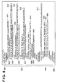
- Fig. 8 is a view showing an example of part of UI configuration setting file expressed in an XML form
- Figs. 9A and 9B are views showing an example of part of a UI configuration setting file expressed in an XML form
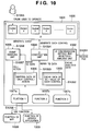
- Fig. 10 is a view showing the logical configuration of an application
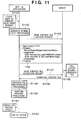
- Fig. 11 is a view showing an operation sequence of an application in the first embodiment
- Fig. 12 is a view showing an example of a UI provided on a display/touch panel unit of an MFP by an application in the second embodiment
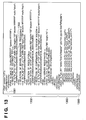
- Fig. 13 is a view showing an example of part of a UI configuration setting file expressed in an XML form
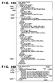
- Figs. 14A and 14B are views showing part of a UI configuration setting file expressed in an XML form
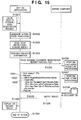
- Fig. 15 is a view showing an operation sequence of an application in the second embodiment
- Figs. 16A and 16B are views showing a display example of a UI
- Fig. 17 is a view showing an example of part of a UI configuration setting file expressed in an XML form
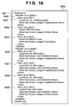
- Fig. 18 is a view showing an example of part of a UI configuration setting file expressed in an XML form.
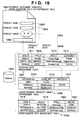
- Fig. 19 is a view for explaining a technique of outputting a document having a database and an insertion field by using a layout engine.
- This embodiment will exemplify pull-type printing which is realized by making an information processing apparatus (server computer) cooperate with an image forming apparatus (MFP (Multi Function Peripheral)).
- server computer server computer
- MFP Multi Function Peripheral
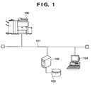
- Fig. 1 is a view showing the arrangement of a system comprising an MFP and a server computer according to an embodiment of the present invention.
- reference numeral 100 denotes an MFP to which a Java (registered trademark) environment can be applied; 101, a network; and 102, a server computer.
- the server computer 102 the following operate: a program for managing communication with the MFP 100, a file creation program for constructing a UI provided for the MFP 100, a document management server, and a server application to function as a content server.
- Reference numeral 103 denotes a database system or file storage system functioning as a storage means which the server computer 102 can use.
- the server computer 102 searches for information associated with a designated product from the database system, and can generate a catalog upon determining the layout of product information and image information on the basis of the found information. This processing is provided by the function of the server application in the server computer 102.
- Reference numeral 104 denotes a client PC which is connected to the server computer 102 and is used by an operator to perform processing.
- the operator can designate items (e.g., a product designation box, a spot advertisement box, a print quality box, and a document type box) for constructing a UI to be provided for the MFP 100 in advance through the client PC 104.
- a server application on the server computer 102 can create a UI configuration setting file based on the items designated by the client PC 104, and register the file in an HDD 406 (Fig. 4) of the server computer 102.
- designation of items for constructing a UI and creation and registration of a UI configuration setting file can be performed by using the server computer 102.
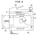
- Fig. 2 is a view for explaining the detailed arrangement of the MFP 100 shown in Fig. 1.
- Reference numeral 200 denotes an automatic document feeding unit (to be referred to as a "feeder” hereinafter); 201, a document scanning unit; 202, a display/touch panel unit; 203, a paper feed unit; 204, a fixing unit; 205, a paper discharge unit; 206, a finishing apparatus; 207, a paper discharge tray, and 208, a print engine unit.
- a feeder an automatic document feeding unit
- 201 a document scanning unit
- 202 a display/touch panel unit
- 203 a paper feed unit
- 204 a fixing unit
- 205 a paper discharge unit
- 206 a finishing apparatus
- 207 a paper discharge tray, and 208, a print engine unit.
- Fig. 3 is a block diagram showing the logical configuration of an information processing function in the MFP 100.
- Reference numeral 300 denotes a display/touch panel unit which provides a user interface (UI) for a user; 301, a network interface unit which communicates with an external device through the network 101; 302, a CPU which executes a program for controlling the MFP 100; 303, a ROM in which a preinstalled program and data are recorded; 304, a RAM as a memory area which can be used by a CPU and used for processing by a program; and 305, an HDD as a large-capacity storage area to which each unit is connected through an input/output interface 306.
- UI user interface
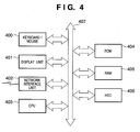
- Fig. 4 is a block diagram showing the logical configuration of an information processing function in the server computer (PC) 102 and client PC 104 shown in Fig. 1.
- Reference numeral 400 denotes an input control unit for a keyboard/mouse which receives inputs from a user; 401, a display unit which provides an output window for the user; 402, a network interface unit which communicates with an external device through a network; 403, a CPU which executes a control program; 404, a ROM in which a built-in application and data are recorded; 405, a RAM as a memory area which can be used by the CPU and used for processing by an application; and 406, an HDD as a large-capacity storage device to which each unit is connected through an input/output interface 407.
- Fig. 5 is a view showing a software configuration associated with an application program which can be executed in the MFP 100.
- the software configuration comprises each module of the real-time OS 501 which can control each type of function of the MFP 100 in real time, or libraries which can control each function of the MFP 100 by issuing instructions to the CPU 302.
- Each function of the MFP 100 is implemented by modules which provide interface commands to an application which operates on the MFP 100; 502, a controller control unit which operates on a real-time OS 501 and comprises modules for controlling the scanning unit 201, the print engine unit 208, a modem communication unit, a PDL rasterization unit, and the like which constitute the MFP 100; and 503, an application programming interface (to be referred to as an API hereinafter).
- an API application programming interface
- the API 503 has a function of controlling the network interface unit 301 and processing for accessing the controller control unit 502 in response to an instruction input from an application.
- Reference numeral 504 denotes an optimal execution environment for the execution of a specific application and is implemented by a Java (registered trademark) virtual machine; and 505, a resource management unit which manages the resources used by the virtual machine 504 and operates on the real-time OS 501.
- the resource management unit 505 restricts all applications on the virtual machine 504 itself which realizes the execution environment, the API 50, or the real-time OS 501 so as to inhibit them from using resources such as a memory up to a predetermined amount or more when using the resources.
- Reference numerals 506, 507, and 508 denote applications which can operate in the MFP 100. Assume that in the following description, the application 506 (application A) is a target application.
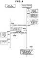
- Fig. 6 is a view showing an operation sequence for constructing a customized UI.
- a manager registers the address of the MFP 100 in the server computer 102.
- a UI configuration setting file is registered.
- step S603 the server computer 102 assigns the UI configuration setting file registered in step S602 to the MFP 100.
- step S604 the server computer 102 registers the server address of the server computer 102 itself in the MFP 100 in which the application 506 operates.
- step S605 the application 506 in the MFP 100 transmits a UI configuration setting file acquisition request to the server computer 102 for the server address registered in step S604.
- step S606 the server computer 102 reads out the UI configuration file assigned to the MFP 100, and the application 506 in the MFP 100 downloads the UI configuration setting file from the server computer 102.
- step S607 the application 506 stores the downloaded UI configurations setting file in the HDD 305, and analyzes the contents of the UI configuration setting file. A UI is then constructed on the basis of the analysis result (S608).
- the server computer 102 can register an arbitrary UI configuration setting file in another MFP and assign it thereto.
- another MFP can construct a user interface window corresponding to a user' purpose in accordance with the individually assigned UI configuration setting file (5609).
- Fig. 7 is a view showing an example of a UI 700 provided on the display/touch panel unit 202 of the MFP 100 by the application 506.
- This example of the UI 700 is aimed at the creation of an advertisement for digital cameras to be printed.
- reference numeral 701 denotes a display/selection unit which can display an application name and select an application.
- applications which can be selected are displayed in a pull-down menu. Applications can be switched by the operation of the display/selection unit 701.
- Reference numeral 702 denotes a frame of the UI 700 displayed on the display/touch panel unit 202; 703, a product designation box; 704, a spot advertisement designation box; and 705, a print quality designation box.
- the designation boxes 703 to 705 are boxes indicating exemplary designation contents aimed at the creation of an advertisement for digital cameras.
- the gist of the present invention is not limited to the display contents. Assume that each application in the MFP 100 can construct a user interface window suitable for the specifications required by a user on the basis of the contents of a UI configuration setting file corresponding to a user's purpose.
- Reference numeral 706 denotes a control button for designating a print output based on the designation information file created by the server computer 102.
- data corresponding to a product or the like designated by each designation box (703 or 704) is sent as an argument to the server computer 102.
- each data sent to the server computer 102 is catalog creation information for creating a catalog.
- the catalog created by the server computer 102 is downloaded into the MFP 100, and printing processing is executed under the control of the CPU 302. The details of pull-type printing processing executed by the server computer 102 and the MFP 100 in cooperation with each other will be described later with reference to Fig. 11.
- Figs. 8, 9A, and 9B are views showing an example of part of a UI configuration setting file expressed in an XML (Extensible Markup Language) form.
- a root node UIConfiguration (801) includes a Components node (802) and an ActionMapping node (803).
- the Components node (802) includes UI configuration information for constructing a UI, and information (function selection information) of an action call for executing processing designated from the UI.
- UI configuration information in the Components node (802) is, for example, identification information 804 which identifies a panel element (Panel) forming a UI display in Fig. 7.
- Reference numeral 809 denotes attribute information for concretely specifying the display position, size, and the like of the panel.
- the application 506 can construct a UI by controlling the display of UI configuration elements on the basis of the identification information 804 and the attribute information 809 corresponding to the identification information 804 under the control of the CPU 302.
- identification information (List) 805 is described as a constituent element for the formation of a UI for a product designation box, and the display position, size, and the like of a product designation box are specified by corresponding attribute information 810.
- the application 506 can construct a UI by controlling the display of the product designation box in the UI under the CPU 302 on the basis of the identification information (List) 805 and the attribute information 810.
- identification information (List) 806 is described as a constituent element for the formation of a UI for a spot advertisement designation box, and the display position, size, and the like of a spot advertisement designation box are specified by corresponding attribute information 811.
- the application 506 can construct a UI by controlling the display of the spot advertisement designation box in the UI under the CPU 302 on the basis of the identification information (List) 806 and the attribute information 811.
- identification information (Choice) 807 is described as a constituent element for the formation of a UI for a print quality designation box, and the display position, size, and the like of a print quality designation box are specified by corresponding attribute information 812.
- the application 506 can construct a UI by controlling the display of the print quality designation box in the UI under the CPU 302 on the basis of the identification information (Choice) 807 and the attribute information 812.
- Identification information (Button) 808 is described as a constituent element of a UI which is a button element for designating the start of printing, and the display position, size, and the like of a button element are specified by corresponding attribute information 813.
- label information 814 information to be displayed in addition to the button element is described.
- the application 506 can construct a UI by controlling the display of the button element in the UI under the CPU 302 on the basis of the identification information (Button) 808, attribute information 813, and label information 814.
- reference information such as a text to be displayed is described as a DataRef element.
- the application 506 can construct a UI by using reference information such as a text to be displayed in addition to the above identification information and attribute information.
- An XML 900 in Fig. 9A describes the contents of reference information (DataRef element) in the XML 800 in Fig. 8.
- a root node DataSource (901) includes a DataSet element (902) and Data elements (903, 904, and 905).
- the Data elements (903, 904, and 905) described in the DataSet element (902) are referred to as display data for the construction of a UI on the basis of the reference data 850 in the XML 800.
- reference numeral 815 denotes a line on which an operation (Target Action) to be executed when the control button 706 is pressed (when a control event occurs) is described.
- an operation to be executed at the occurrence of a control event "act_001" is described on the line 815.
- information which can be used as the attribute (type) of an action includes, for example, the function name of a program module and a URI.
- An action element further includes an Arguments node and allows data selected or input by the user through the display of each designation box to be provided as an argument (820, 821, and 822).
- Figs. 8, 9A, and 9B exemplify a UI configuration setting file.
- the gist of the present invention is not limited to this configuration.
- the application 506 can flexibly change the configuration of the UI.
- the UI configuration setting file is not limited to an XML form, and may be described in the form of, for example, a text file, binary file, or data stream.
- Fig. 10 is a view showing the logical configuration of the application 506.
- Reference numeral 1000 denotes an overall application.
- a UI configuration setting file reception/analysis unit 1002 receives the UI configuration setting file downloaded from the server computer 102 and analyzes its contents.
- step S1052 the UI configuration setting file reception/analysis unit 1002 stores the data of the analyzed UI configuration setting file in storage areas 1003 and 1006.
- the cache data of a set value (attribute information or the like) associated with each constituent element (control) for the construction of a UI is stored in the storage area 1003.
- the mapping data of an action designated from the UI is stored in the storage area 1006.
- a UI construction unit 1004 refers to the data (identification information, attribute information, and the like) in the file storage system 103, and generates each constituent element (each control) for the construction of a UI, thereby constructing a UI 1001 (S1054).
- each control is generated as, for example, a constituent element 703 or 704 shown in Fig. 7.
- n controls (Control 1, 2, 3,... n) are generated as constituent elements of the UI 1001.
- the event handling unit 1005 refers to the mapping data in the storage area 1006 and calls an action assigned to the corresponding control (operation/setting). Assume that the event handling unit 1005 can select a function for executing an action corresponding to a generated event, and call, for example, function modules 1007a, 1007b, and 1007c in the application 506.
- the function module 1007a can be configured to use a function 1008 of the MFP through an API or a function 1009 provided by a server application.
- the functions of the MFP 100 include a printing function, a facsimile function, a scanning function, and the like. Assigning the respective functions to the function modules 1007a, 1007b, and 1007c makes it possible to selectively use the functions of the MFP 100.
- the functions of a server application cooperated with the MFP 100 include, for example, a function of searching for data designated through the UI, creating a data layout and a file of laid out data as a print target, and downloading the file.
- the functions of a server application cooperated with the scanning function of the MFP 100 includes a function associated with registration processing of data input by the scanning unit 201.
- step S1151 the user designates the model name of a digital camera, a spot advertisement, and a print quality by controls (the product designation box 703, spot advertisement designation box 704, and print quality designation box 705) using the UI 700.
- the start of printing is designated from the control button 706, an event is generated, and a corresponding action is selected from the function modules 1007a, 1007b, and 1007c by referring to the mapping data of the action.
- step S1152 the selected function module 1007a is called, and processing is started.
- Reference numeral 910 in Fig. 9B denotes an example of a request which is notified to the function module 1007a and is expressed in XML.
- a root node Action (924) includes a name (Name) node 925 and an argument (Arguments) node 926.
- a function module can be called by assigning argument data to each argument element (931 to 933) following the argument node 926. The content of each argument element (931 to 933) can be identified by an attribute key in the argument element. This makes it possible to process data associated with a plurality of argument elements at once.
- the function module 1007a analyzes a call request for an action, generates a content file creation request (function request information), and transmits the request to the server application (S1153).
- the content of the content file creation request is based on the content of the request (Fig. 9B) notified to the function module 1007a.
- Reference numeral 1100 in Fig. 11 denotes an example of a content file creation request expressed in XML.
- a root node (Request) (1101) includes a name (Name) node (1102) and an argument (Arguments) node (1103).
- Argument data is assigned to each argument in the argument node (1103).
- Argument data is data selected by a customized UI. This data is transferred to the server application.
- the server application executes data retrieval/layout/file creation function by using the transferred argument data.
- argument "0622A001" and spot advertisement type "AdvPrinter” are prepared as specific information in accordance with the above designation through the operation panel.
- the application transmits a prepared argument to the server computer 102 to transfer it to the layout engine.
- the server computer 102 calls the layout engine and automatically creates a file in which character data, image data, and the like are laid out (S1156).
- the details of step S1156 will be described with reference to Fig. 19.
- Fig. 19 is a view for explaining a technique to which the present invention is applied and which outputs a document having a database and an insertion box by using the layout engine.
- Reference numeral 1901 denotes an example of a document (document template) having an insertion field and an advertisement field.
- the example 1901 includes a field 1902 ("insertion field A") in which "model name” data is to be inserted, a field 1903 ("insertion field B") in which "product code” data is to be inserted, a field 1904 (“insertion field C”) in which "product image” data is to be inserted, and a field 1905 (“advertisement area”) in which an advertisement is to be inserted, and layout information which determines reference positions where the fields are to be placed is also taken into consideration.
- This file can also use PDF (Portable Document Format) as a format for electronic documents.
- PDF Portable Document Format
- a page description language (PDL) or the like can be used.
- the application 506 transmits a file acquisition request to the server application (S1157), and downloads the file created by the server application (S1158).
- the application 506 calls the function 1008 of the MFP through the API or the like, and performs PDL rasterization processing and printing processing (S1159 and S1160).
- a print quality (print_quality_dpi) provided as argument data of an XML 910 is used, and the printing function of the MFP 100 is controlled.
- print_quality_dpi provided as argument data of an XML 910
- the application range of the present invention includes the use of the arbitrary providing function of the server computer from the MFP, and is not limited to this example.
- the security of information can be protected by encrypting communication between the MFP 100 and the server computer 102 using an encryption means.
- Each application of the MFP 100 can construct a user interface window suitable for the specifications required by the user on the basis of the contents of a UI configuration setting file corresponding to a user's purpose.
- An example of a UI in a display form different from that of the UI shown in Fig. 7 will be described with reference to Figs. 16A to 18.
- Fig. 16A is a view showing a UI 1600 for designating a product category.
- the user can select "digital camera”, “printer”, “facsimile”, and the like from a designation box (1601).
- the UI 1600 is switched to display a UI 1603 in Fig. 16B.
- Fig. 16B is a view showing the UI 1603 for the designation of a specific product in the product category (digital camera) designated in the UI 1600 described above.
- the flow of processing then shifts to printing processing similar to that in the case of the print in Fig. 7 described above.
- the application can further construct a UI following the UI in Fig. 16B on the basis of the contents of a UI configuration setting file.
- Figs. 17 and 18 are views showing examples of UI configuration setting files associated with the UI display in Figs. 16A and 16B.
- a root node UIConfiguration (1701) includes a Components node (1702) and an ActionMapping node (1703).
- the Components node includes UI configuration information for the construction of a UI
- the ActionMapping node includes information (function selection information) of an action call for executing processing designated from the UI.
- An XML 1800 in Fig. 18 is designed to describe the contents of reference information (DataRef element) in the XML 1700 in Fig. 17.
- a root node DataSource (1801) includes a DataSet element (1802) and Data elements (1803, 1804, and 1805).
- Data 1803 to 1805 described in a data set 1802 are based on reference data 1750 in the XML 1700 and are referred to as display data for the construction of a UI.
- the application retrieves data 1806 to 1809 of a product category matching the item designated by the user from the reference information (application retrieves data 1806 to 1809) associated with "panel_02", and displays the retrieved data in a product designation box 1604.
- a user interface window can be constructed in a display form suitable for the specifications required by the user by changing the contents of the UI configuration setting file.
- the button "print” (1606) in Fig. 16B is clicked, an event is generated. The flow of processing then shifts to printing processing similar to that in the case of the print in Fig. 7 described above.
- a user interface window can be constructed in accordance with a user's purpose, and an image can be formed by using a function unique to the MFP and the function of a server application upon setting through the user interface window.
- a server application registers a scanned document file obtained by using the scanning function of an MFP 100 in a file storage system 103 functioning as a storage means.
- a description of contents which are associated with system configurations, the logical configuration of an application, and the like and are redundant to those in the first embodiment will be omitted.
- Fig. 12 is a view showing an example of a UI provided on a display/touch panel unit 202 of the MFP 100 by an application 506 as in the case shown in Fig. 7 in the first embodiment.
- a document type designation box (1203), server registration processing designation box (1204), scanning resolution designation box (1205), and confirmation designation box (1206) on a previous image can be designated.
- a scanning unit 201 of the MFP 100 creates a scanned document file by scanning an original set on an original plate or a feeder 200 (Fig. 2) at a designated resolution. This scanned document file is displayed in a previous window on the display/touch panel unit 202, and is transmitted to a server computer 102 in accordance with the confirmation made by the user.
- the server computer 102 then performs the registration processing designated by a UI 1200 to register the file as the data of a designated document type in the file storage system 103 functioning as a storage means.
- reference numeral 1201 denotes a display/section unit capable of displaying an application name and selecting an application.
- the display/section unit 1201 When the display/section unit 1201 is selected, for example, applications which can be selected are displayed in a pull-down menu. Applications can be switched with each other by operating the display/section unit 1201.
- Reference numeral 1202 denotes a frame of the UI 1200 which is displayed on the display/touch panel unit 202.
- Reference numeral 1203 denotes a document type designation box; 1204, a server registration processing designation box; 1205, a scanning resolution designation box 1205; 1206, a designation box for determining whether to perform confirmation in a previous window; and 1207, a control button for the registration of a scanned/input document file in the server computer.
- the gist of the present invention is not limited to these display contents. Assume that each application in the MFP 100 can construct a user interface window suitable for the specifications required by a user on the basis of the contents of a UI configuration setting file corresponding to a user's purpose.
- Figs. 13, 14A, and 14B are views showing an example of part of a UI configuration setting file expressed in XML.
- An application in the MFP 100 can construct a UI in accordance with the contents described in the UI configuration setting file.
- a root node UIConfiguration (1301) includes a Components node (1302) and an ActionMapping node (1303).
- the Components node (1302) includes UI configuration information for the construction of a UI.
- the ActionMapping node (1303) includes information (function selection information) of an action call for executing processing designated from the UI.
- the application in the MFP 100 can construct a UI by controlling the display of the constituent elements of the UI on the basis of identification information which identifies each constituent element and attribute information corresponding to the identification information.
- reference information in the XML in Fig. 13 includes a DataSet element (1402) and Data elements (1403, 1404, and 1405) .
- Buttons are defined as elements. Elements include element names and attributes. Each element can be accompanied by a sub-element.
- Data is defined as a sub-element. Data further has a Label element and a Value element as subelements. The character string set in the Label element as a result of analysis of XML data is used as the display name of a button. The Value element has a key as an attribute. The Key attribute is used to designate a document type. If, for example, a receipt button is pressed, the character string "Receipt" is acquired as a Key attribute by the MFP 100. The MFP 100 may transmit this acquired character string to the server computer in accordance with a transmission instruction.
- An element having the attribute id_ds0102 of the Dataset element will be further described. This is associated with the server registration processing designation box 1204 for designating how data read in by the scanner is processed by the server computer.
- a button including the character string of the electronic signature is displayed.
- the value "save option" is set for the attribute key of the value element.
- eSignature is set as the content of the value element.
- the transmission button is pressed while the electronic signature button is pressed once, the character string "eSignature” is transmitted as the value of save_option to the server computer. If the value of save_option added to the data is eSignature, the server computer performs electronic signature processing. If the value of save_option is Time_Stamp, the server computer performs time stamp processing.
- the third DataSet (id attribute is id_0203) will be described next.
- a Label element is displayed as a button.
- the content of selected Value (numeral information selected from 600 and 200) is acquired as a selected resolution by the MFP 100. If, for example, the 300-dpi button is pressed, the MFP 100 performs scanning processing for a document at a resolution of 300 dpi.
- step S1551 the user designates the document type 1203, the server registration processing designation box 1204, the scanning resolution designation box 1205, and the designation box of the confirmation 1206 on a preview image by using the UI 1200.
- the scanning/registration is designated with the control button 1207, an event is generated, and a corresponding action is selected from function modules 1007a, 1007b, and 1007c by referring to the mapping data of the action.
- step S1552 the selected function module (the function module 1007c corresponding to the scanning function in this case) is called, and the processing is started.
- Reference numeral 1410 in Fig. 14B denotes an example of a request which is notified to the function module 1007c and expressed in XML.
- a root node Action (1424) includes a name (Name) node 1425 and an argument (Arguments) node 1426.
- a function module can be called by assigning argument data to each argument element (1431 to 1435) following the argument node 1426. The content of each argument element (1431 to 1435) can be identified by an attribute key in the argument element. This makes it possible to process data associated with a plurality of argument elements at once.
- the function module 1007c analyzes a call request for an action, and controls the function of the MFP through an API or the like so as to scan/input an original at a designated resolution.
- the function module 1007c creates a scanned document file on the basis of the scanned/input data (51553).
- step S1554 if confirmation in a preview window is designated, the application 506 displays the preview window on the display/touch panel unit 202. In addition, the application 506 displays a confirmation dialog on the display/touch panel unit 202, as needed.
- step S1555 the function module 1007c analyzes a call request for an action, generates a scanned document registration request (function request information), and transmits the request to the server application (S1555).
- the content of the scanned document registration request is based on the content of the request (Fig. 14B) notified to the function module 1007c.
- the function module 1007c transmits the scanned document registration request to the server application on the server computer 102, and uploads the scanned document file.
- reference numeral 1500 denotes an example of a scanned document registration request expressed in XML.
- a root node (Request) (1501) includes a name (Name) node (1502) and an argument (Arguments) node (1503).
- Argument data is assigned to each argument in the argument node 1503.
- Argument data is data selected through a customized UI. This data is transferred to the server application.
- the server application executes a function associated with the registration of contents by using the transferred argument data.
- the server application analyzes a scanned document registration request, and detects whether registration processing (save_option), an electronic signature (eSignature), and a time stamp (TimeStamp) are designated. Since registration processing, an electronic signature, and a time stamp are designated in the scanned document registration request 1500, the server application executes electronic signal processing, time stamp processing, and registration processing for the scanned document file in accordance with the designation.
- the server application executes the electronic signature processing in step S1556, time stamp processing in step S1557, and registration processing with respect to a document DB in step S1558.
- the server application registers it as a receipt (Receipt) as a document type (document_type) designated by argument data.
- step S1559 when the registration processing by the server application is complete, the processing result is notified to the application 506 of the MFP 100.
- step S1560 when all the processing starting from action calling is complete, the application 506 displays the processing result in the UI. In this case, the application 506 can leave a record of the processing result so as to allow the user to check the log as well as displaying the result in the UI.
- the security of information can be protected by encrypting communication between the MFP 100 and the server computer 102 using an encryption means.
- a user interface window can be constructed in accordance with a user's purpose, and an image can be formed by using a function unique to a multi function peripheral and the function of a server application in accordance with settings from the user interface window.
- the MFP 100 which communicates with the server computer 102 displays, on the operation unit, a window for allowing the user to input an instruction to cause the information processing apparatus to execute a dynamic layout function.
- the dynamic layout function is, for example, a function of dynamically determining a layout based on document template data including insertion data and layout information for laying out the insertion data so as to form an image by merging the document template.
- specifying information to be used when processing is performed by using the dynamic layout function of the server computer 102 is transmitted to the server computer 102.
- specifying information a product code and a spot advertisement type have been described.
- the server computer 102 receives the data dynamically laid out by using the specifying information.
- the MFP 100 outputs the received data by using the print engine.
- the MFP 100 acquires configuration data in which information for the construction of a user interface is set. The MFP 100 then analyzes the configuration data. The operation unit of the MFP 100 displays a window for inputting an instruction to execute dynamic layout processing.
- the MFP 100 is an apparatus which can input specifying information for specifying insertion data and template data. The MFP 100 then transmits the input specifying information.
- the MFP 100 receives the data dynamically laid out by the server computer 102 on the basis of the insertion data and template data specified by the transmitted specifying information.
- the MFP 100 prints out the received data through the print engine.
- the MFP 100 which communicates with the server computer 102 may be configured as follows.
- the MFP may comprise a network interface unit 301 which acquires configuration data in which information for the construction of a user interface is set.
- the configuration data (e.g., the data shown in Figs. 13, 14A, and 14B) acquired through the network interface unit 301 is processed to display, on an operation unit (display/touch panel unit 300), a window for inputting an instruction to execute image processing in which the data processed by using the scanner function of the MFP 100 is processed by using the function of the server computer 102.
- a CPU 302 executes scanning processing in accordance with the instruction input through the window displayed on the operation unit.
- the MFP 100 also comprises a network interface unit 301 which transmits, to the server computer 102, the data obtained when the CPU 302 executes the scanner function of the MFP 100 and processing information (a scanned document registration request 1500) which is used to process the data by using the function of the server computer 102.
- a network interface unit 301 which transmits, to the server computer 102, the data obtained when the CPU 302 executes the scanner function of the MFP 100 and processing information (a scanned document registration request 1500) which is used to process the data by using the function of the server computer 102.
- the display/touch panel unit 300 analyzes the configuration data acquired by the MFP 100 using the network interface unit 301, and displays a window for inputting an instruction to execute image processing for the data input by using the scanner of the MFP 100 by executing a program installed in the server computer 102.
- the scanner function of the MFP 100 is executed under the control of the CPU 302 in accordance with an instruction input through the window displayed by the display/touch panel unit 300.
- the data input when the CPU 302 executes the scanner function and a parameter or command (scanned document registration request 1500) used to perform image processing for the data by using a program installed in the server computer 102 are transmitted through the network interface unit 301.
- the server computer 102 receives the transmitted scanned document registration request 1500.
- the server computer 102 may provide time stamp processing for adding information indicating the time.
- an instruction window for issuing an instruction to execute time stamp processing in the server computer 102 may be displayed on the operation unit of the MFP 100.
- the processing of the scanner function of the image forming apparatus may be executed under the control of the CPU 302 in accordance with an instruction to operate the scanner which is issued through the display/touch panel unit 300.
- the transmission means transmits, to the server computer 102, processing information (the scanned document registration request 1500 including the time stamp instruction) including control information set by the operation of the user interface displayed on the display/touch panel unit 300.
- the server computer 102 may be caused to perform time stamp processing for the image data input by the scanner function of the MFP 100 and register the resultant data.
- the object of the present invention is achieved even by supplying a storage medium storing software program codes for implementing the functions of the above first and second embodiments to a system or apparatus, and causing the computer (or a CPU or an MPU) of the system or apparatus to read out and execute the program codes stored in the storage medium.
- the program codes read out from the storage medium implement the functions of the above embodiments by themselves, and the storage medium storing the program codes constitutes the present invention.
- a flexible disk As a storage medium for supplying the program codes, a flexible disk, a hard disk, an optical disk, a magnetooptical disk, a CD-ROM, a CD-R, a magnetic tape, a nonvolatile memory card, a ROM, or the like can be used.
- An image forming apparatus which communicates with an information processing apparatus includes a display unit which is used to input an instruction to cause the information processing apparatus to execute a dynamic layout function of dynamically determining a layout on the basis of template data so as to form an image by using template data including insertion data and layout information, a transmission unit which transmits, to the information processing apparatus, specifying information to be used when processing is performed by using the dynamic layout function, a reception unit which receives dynamically laid out data, and an output unit which outputs the received data.
Landscapes
- Engineering & Computer Science (AREA)
- Multimedia (AREA)
- Signal Processing (AREA)
- General Engineering & Computer Science (AREA)
- Human Computer Interaction (AREA)
- Computing Systems (AREA)
- Facsimiles In General (AREA)
- Accessory Devices And Overall Control Thereof (AREA)
- Editing Of Facsimile Originals (AREA)
- Record Information Processing For Printing (AREA)
Applications Claiming Priority (1)
| Application Number | Priority Date | Filing Date | Title |
|---|---|---|---|
| JP2005246431A JP4115474B2 (ja) | 2005-08-26 | 2005-08-26 | 画像形成装置及び画像形成装置の制御方法、画像形成システム、プログラム及び記憶媒体 |
Publications (2)
| Publication Number | Publication Date |
|---|---|
| EP1758364A2 true EP1758364A2 (de) | 2007-02-28 |
| EP1758364A3 EP1758364A3 (de) | 2007-03-07 |
Family
ID=37397819
Family Applications (1)
| Application Number | Title | Priority Date | Filing Date |
|---|---|---|---|
| EP06119327A Withdrawn EP1758364A3 (de) | 2005-08-26 | 2006-08-22 | Bilderzeugungsgerät anzeigt eine aus einem Server, dynamisch erzeugte Benutzerschnittstelle und empfängt aus dem Server, dynamisch erzeugten auszudruckenden Documenten. |
Country Status (4)
| Country | Link |
|---|---|
| US (1) | US7924452B2 (de) |
| EP (1) | EP1758364A3 (de) |
| JP (1) | JP4115474B2 (de) |
| CN (1) | CN1921547B (de) |
Cited By (5)
| Publication number | Priority date | Publication date | Assignee | Title |
|---|---|---|---|---|
| EP1852748A1 (de) * | 2006-05-02 | 2007-11-07 | Ricoh Company, Ltd. | Bildhandhabungsvorrichtung, Bildverarbeitungssystem, Steuerverfahren für die Bildverarbeitung und Programmprodukt zum Steuern der Bildverarbeitung |
| EP2015554A1 (de) * | 2007-07-13 | 2009-01-14 | Ricoh Company, Ltd. | Verfahren zur Erzeugung von Benutzerschnittstellen, Bildgebungsvorrichtung und Computerprogrammprodukt |
| US7957021B2 (en) | 2005-05-20 | 2011-06-07 | Ricoh Company, Ltd. | Image handling apparatus, image processing system, image process controlling method, and image process controlling program product |
| EP2348402A1 (de) * | 2009-12-16 | 2011-07-27 | Samsung Electronics Co., Ltd. | Bilderzeugungsvorrichtung und Verfahren zur Bereitstellung einer lokalen Benutzerschnittstelle dafür |
| EP2355486A1 (de) * | 2010-02-02 | 2011-08-10 | Ricoh Company, Ltd. | Verfahren und Systeme zum Netzwerkdrucken mit vom Benutzer auswählbaren Einstellungen |
Families Citing this family (27)
| Publication number | Priority date | Publication date | Assignee | Title |
|---|---|---|---|---|
| JP4474440B2 (ja) | 2007-06-19 | 2010-06-02 | インターナショナル・ビジネス・マシーンズ・コーポレーション | 多機能周辺装置(mfp)によるサービスの提供 |
| US8165404B2 (en) * | 2007-09-19 | 2012-04-24 | Ricoh Company, Ltd. | Method and apparatus for creating document data, and computer program product |
| JP2010039938A (ja) * | 2008-08-07 | 2010-02-18 | Fuji Xerox Co Ltd | 文書処理装置及び文書処理プログラム |
| JP5284135B2 (ja) * | 2009-02-18 | 2013-09-11 | キヤノン株式会社 | 画像処理装置及びその制御方法並びにプログラム |
| JP5293288B2 (ja) | 2009-03-10 | 2013-09-18 | 株式会社リコー | 画像形成装置、情報処理装置、情報処理方法、及びプログラム |
| US8756489B2 (en) * | 2009-09-17 | 2014-06-17 | Adobe Systems Incorporated | Method and system for dynamic assembly of form fragments |
| JP5120390B2 (ja) * | 2010-02-10 | 2013-01-16 | ブラザー工業株式会社 | 情報処理装置及びスキャナ装置 |
| US8887054B2 (en) | 2010-04-15 | 2014-11-11 | Hewlett-Packard Development Company, L.P. | Application selection user interface |
| US9223890B2 (en) | 2011-03-15 | 2015-12-29 | Hewlett-Packard Development Company, L.P. | System and method of processing content using a uniform resource identifier |
| US9092167B2 (en) | 2011-04-04 | 2015-07-28 | Hewlett-Packard Development Company, L.P. | Systems and methods for managing a print job |
| JP2014527921A (ja) * | 2011-06-29 | 2014-10-23 | マーケム−イマージュ ホールディング | 動的ユーザインタフェース |
| US10154163B2 (en) | 2011-06-29 | 2018-12-11 | Markem-Imaje Holding | Dynamic user interface |
| JP5500128B2 (ja) | 2011-07-14 | 2014-05-21 | コニカミノルタ株式会社 | アプリ連携システムおよびアプリ連携方法 |
| JP2013152666A (ja) * | 2012-01-26 | 2013-08-08 | Canon Inc | 管理システム、画像形成装置、管理システムの制御方法、画像形成装置の制御方法、プログラム |
| US10789412B2 (en) * | 2012-02-20 | 2020-09-29 | Wix.Com Ltd. | System and method for extended dynamic layout |
| US9716802B2 (en) | 2012-04-12 | 2017-07-25 | Hewlett-Packard Development Company, L.P. | Content model for a printer interface |
| CN103533206B (zh) * | 2012-07-03 | 2016-08-10 | 株式会社理光 | 图像处理系统及处理方法、图像处理装置、遥控终端装置 |
| JP6155899B2 (ja) * | 2012-07-12 | 2017-07-05 | 株式会社リコー | 情報処理システム、情報処理装置、機器、情報処理方法、及びプログラム |
| JP2014203268A (ja) * | 2013-04-04 | 2014-10-27 | キヤノン株式会社 | 情報処理装置及び制御方法 |
| JP5987785B2 (ja) * | 2013-05-31 | 2016-09-07 | 富士ゼロックス株式会社 | 処理指示装置、処理装置およびプログラム |
| JP2014235515A (ja) * | 2013-05-31 | 2014-12-15 | 富士ゼロックス株式会社 | 処理指示装置、処理装置およびプログラム |
| JP2015064682A (ja) * | 2013-09-24 | 2015-04-09 | Necプラットフォームズ株式会社 | 外部サービス連携システム、外部サービス連携装置、外部サービス連携方法、および、コンピュータ・プログラム |
| JP6911313B2 (ja) * | 2016-09-26 | 2021-07-28 | 富士フイルムビジネスイノベーション株式会社 | 画像形成装置及びプログラム |
| JP6558339B2 (ja) * | 2016-10-06 | 2019-08-14 | 京セラドキュメントソリューションズ株式会社 | 画像処理装置及び画像処理プログラム |
| US10996997B2 (en) * | 2017-01-23 | 2021-05-04 | International Business Machines Corporation | API-based service command invocation |
| JP7241982B1 (ja) * | 2022-02-15 | 2023-03-17 | 三菱電機株式会社 | 画像生成プログラム、画像生成装置、プログラマブルコントローラシステム及び画像生成方法 |
| US12328421B2 (en) * | 2023-06-30 | 2025-06-10 | Konica Minolta Business Solutions U.S.A., Inc. | Method and system for automated cryptographic signing for MFP-generated documents |
Citations (7)
| Publication number | Priority date | Publication date | Assignee | Title |
|---|---|---|---|---|
| JP2000196698A (ja) | 1998-12-28 | 2000-07-14 | Canon Inc | マルチファンクションシステム及びそのデ―タ転送方法 |
| JP2000298561A (ja) | 1999-04-14 | 2000-10-24 | Canon Inc | 画像形成システム、制御方法、及び記憶媒体 |
| US20020024685A1 (en) | 2000-08-28 | 2002-02-28 | Wataru Sasaki | Push type scanner apparatus and image data transmitting and receiving system |
| US20030011633A1 (en) | 2001-07-16 | 2003-01-16 | Ecopy, Inc. | Method of and system for dynamically controlling during run time a multifunction peripheral (MFP) touch panel user interface (UI) from an external remote network-connected computer |
| US20030048303A1 (en) | 2001-08-31 | 2003-03-13 | Mesa Christopher A. | Destination direction for push scanning to at least one of multiple destinations |
| US20050088711A1 (en) * | 2003-10-24 | 2005-04-28 | Daniel Stuart W. | Scanning device with preview |
| US20050094178A1 (en) * | 2003-10-17 | 2005-05-05 | Canon Kabushiki Kaisha | Data processing device and data storage device |
Family Cites Families (17)
| Publication number | Priority date | Publication date | Assignee | Title |
|---|---|---|---|---|
| US7124359B2 (en) | 1996-01-11 | 2006-10-17 | Canon Kabushiki Kaisha | Image edit device adapted to rapidly lay-out photographs into templates with means for preview and correction by user |
| JPH11232365A (ja) | 1998-02-19 | 1999-08-27 | Oki Electric Ind Co Ltd | ネットワークを介した帳票印刷方法 |
| JP2000020510A (ja) | 1998-07-06 | 2000-01-21 | Canon Inc | デジタルデータ文書配布方法及びその装置 |
| JP2002024020A (ja) * | 2000-05-01 | 2002-01-25 | Toshiba Corp | 画面制御プログラム、動的表示情報取得プログラム、画面表示トランザクションプログラム、画面コンポーネントインタフェースプログラム、画面プログラム作成方法 |
| US7515288B2 (en) | 2001-04-06 | 2009-04-07 | Sharp Kabushiki Kaisha | Image processing apparatus |
| US6999207B2 (en) | 2001-09-19 | 2006-02-14 | Kabushiki Kaisha Toshiba | Image processing apparatus, image forming apparatus, and method of them |
| JP2003337810A (ja) | 2002-05-21 | 2003-11-28 | Canon Inc | 差込印刷方法 |
| JP2004009356A (ja) | 2002-06-04 | 2004-01-15 | Seiko Epson Corp | 印刷装置 |
| US7068165B2 (en) | 2002-06-21 | 2006-06-27 | Brother Kogyo Kabushiki Kaisha | Environment setup system, electronic apparatus, radio communication terminal, program |
| JP2004288040A (ja) | 2003-03-24 | 2004-10-14 | Fuji Xerox Co Ltd | 画像処理装置、画像処理方法、及び画像処理プログラム |
| JP4402362B2 (ja) | 2003-04-04 | 2010-01-20 | キヤノン株式会社 | 画像読取装置、その制御方法、プログラムおよび記憶媒体 |
| JP2005158032A (ja) | 2003-10-30 | 2005-06-16 | Canon Inc | 情報処理方法及び情報処理装置 |
| JP2005169838A (ja) | 2003-12-11 | 2005-06-30 | Canon Inc | 画像出力装置 |
| US7408667B2 (en) | 2004-02-06 | 2008-08-05 | Sharp Laboratories Of America, Inc. | Systems and methods for pull printing where rendering is initiated at the printer |
| WO2005109172A1 (en) * | 2004-05-12 | 2005-11-17 | Samsung Electronics Co., Ltd. | Method of providing multimedia data for direct printing, direct printing method and apparatus thereof |
| US8115944B2 (en) * | 2004-10-08 | 2012-02-14 | Sharp Laboratories Of America, Inc. | Methods and systems for local configuration-based imaging device accounting |
| US8213034B2 (en) * | 2004-10-08 | 2012-07-03 | Sharp Laboratories Of America, Inc. | Methods and systems for providing remote file structure access on an imaging device |
-
2005
- 2005-08-26 JP JP2005246431A patent/JP4115474B2/ja not_active Expired - Fee Related
-
2006
- 2006-08-17 US US11/465,203 patent/US7924452B2/en not_active Expired - Fee Related
- 2006-08-22 EP EP06119327A patent/EP1758364A3/de not_active Withdrawn
- 2006-08-25 CN CN2006101265378A patent/CN1921547B/zh not_active Expired - Fee Related
Patent Citations (7)
| Publication number | Priority date | Publication date | Assignee | Title |
|---|---|---|---|---|
| JP2000196698A (ja) | 1998-12-28 | 2000-07-14 | Canon Inc | マルチファンクションシステム及びそのデ―タ転送方法 |
| JP2000298561A (ja) | 1999-04-14 | 2000-10-24 | Canon Inc | 画像形成システム、制御方法、及び記憶媒体 |
| US20020024685A1 (en) | 2000-08-28 | 2002-02-28 | Wataru Sasaki | Push type scanner apparatus and image data transmitting and receiving system |
| US20030011633A1 (en) | 2001-07-16 | 2003-01-16 | Ecopy, Inc. | Method of and system for dynamically controlling during run time a multifunction peripheral (MFP) touch panel user interface (UI) from an external remote network-connected computer |
| US20030048303A1 (en) | 2001-08-31 | 2003-03-13 | Mesa Christopher A. | Destination direction for push scanning to at least one of multiple destinations |
| US20050094178A1 (en) * | 2003-10-17 | 2005-05-05 | Canon Kabushiki Kaisha | Data processing device and data storage device |
| US20050088711A1 (en) * | 2003-10-24 | 2005-04-28 | Daniel Stuart W. | Scanning device with preview |
Cited By (15)
| Publication number | Priority date | Publication date | Assignee | Title |
|---|---|---|---|---|
| US9172831B2 (en) | 2005-05-20 | 2015-10-27 | Ricoh Company, Ltd. | Image handling apparatus, image processing system, image process controlling method, and image process controlling program product |
| US10250761B2 (en) | 2005-05-20 | 2019-04-02 | Ricoh Company, Ltd. | Image handling apparatus, image processing system, image process controlling method, and image process controlling program product |
| US7957021B2 (en) | 2005-05-20 | 2011-06-07 | Ricoh Company, Ltd. | Image handling apparatus, image processing system, image process controlling method, and image process controlling program product |
| US8823992B2 (en) | 2005-05-20 | 2014-09-02 | Ricoh Company, Ltd. | Image handling apparatus, image processing system, image process controlling method, and image process controlling program product |
| US8570571B2 (en) | 2005-05-20 | 2013-10-29 | Ricoh Company, Ltd. | Image handling apparatus, image processing system, image process controlling method, and image process controlling program product possible to provide an interface capable of controlling special hardware mounted in the image forming apparatus |
| US10694051B2 (en) | 2005-05-20 | 2020-06-23 | Ricoh Company, Ltd. | Image handling apparatus for inputting scan settings for a scanner |
| US9521286B2 (en) | 2005-05-20 | 2016-12-13 | Ricoh Company, Ltd. | Image handling apparatus, image processing system, image process controlling method, and image process controlling program product |
| EP1852748A1 (de) * | 2006-05-02 | 2007-11-07 | Ricoh Company, Ltd. | Bildhandhabungsvorrichtung, Bildverarbeitungssystem, Steuerverfahren für die Bildverarbeitung und Programmprodukt zum Steuern der Bildverarbeitung |
| EP3349065A1 (de) * | 2006-05-02 | 2018-07-18 | Ricoh Company Ltd. | Bildverarbeitungsvorrichtung |
| US8468213B2 (en) | 2007-07-13 | 2013-06-18 | Ricoh Company, Limited | Screen generating method, image forming apparatus, and computer program product |
| EP2015554A1 (de) * | 2007-07-13 | 2009-01-14 | Ricoh Company, Ltd. | Verfahren zur Erzeugung von Benutzerschnittstellen, Bildgebungsvorrichtung und Computerprogrammprodukt |
| US9489348B2 (en) | 2007-07-13 | 2016-11-08 | Ricoh Company, Limited | Screen generating method, image forming apparatus, and computer program product |
| EP2348402A1 (de) * | 2009-12-16 | 2011-07-27 | Samsung Electronics Co., Ltd. | Bilderzeugungsvorrichtung und Verfahren zur Bereitstellung einer lokalen Benutzerschnittstelle dafür |
| EP2355486A1 (de) * | 2010-02-02 | 2011-08-10 | Ricoh Company, Ltd. | Verfahren und Systeme zum Netzwerkdrucken mit vom Benutzer auswählbaren Einstellungen |
| US8643856B2 (en) | 2010-02-02 | 2014-02-04 | Ricoh Company, Ltd. | Methods and systems for network printing with user selectable settings |
Also Published As
| Publication number | Publication date |
|---|---|
| US20070046996A1 (en) | 2007-03-01 |
| JP4115474B2 (ja) | 2008-07-09 |
| JP2007060556A (ja) | 2007-03-08 |
| CN1921547A (zh) | 2007-02-28 |
| EP1758364A3 (de) | 2007-03-07 |
| US7924452B2 (en) | 2011-04-12 |
| CN1921547B (zh) | 2010-05-12 |
Similar Documents
| Publication | Publication Date | Title |
|---|---|---|
| US7924452B2 (en) | Image forming apparatus, control method for image forming apparatus, image forming system, and storage medium | |
| US8610922B2 (en) | Information processing apparatus, image input apparatus, document distribution system, and control method therefor | |
| US8326090B2 (en) | Search apparatus and search method | |
| JP5008774B2 (ja) | 画像処理装置及びその制御方法 | |
| US8166382B2 (en) | Data processing apparatus, method of registering electronic document, and computer program | |
| US20080294983A1 (en) | Display control apparatus, display control method, display control program | |
| US8373878B2 (en) | Cooperative job flow creating apparatus, cooperative job flow creating method, service processing apparatus, service processing method, management server, flow conversion method, job flow execution method, program, and storage medium | |
| JP4317162B2 (ja) | プリントサーバおよび印刷管理サーバおよび印刷装置およびプリントシステムおよび印刷データ蓄積方法および印刷管理方法および印刷方法およびプログラム | |
| US20080178199A1 (en) | Information processing device, image processing apparatus, information processing method, and storage medium | |
| JP5634132B2 (ja) | 情報処理システム、情報処理装置、それらの制御方法及びプログラム | |
| JP4125097B2 (ja) | 電子化原稿管理装置及びその制御方法、電子化原稿管理システム、プログラム | |
| JP2007257528A (ja) | 文書検索装置、文書管理システム、文書検索システムおよび文書検索方法 | |
| JP4455640B2 (ja) | 画像形成装置、画像形成装置の制御方法、画像形成システム、プログラム及び記憶媒体 | |
| JP4745866B2 (ja) | デバイス管理システムおよびその制御方法 | |
| US20040205758A1 (en) | Service processing system and service processing method | |
| JP4040568B2 (ja) | 画像処理システムおよびジョブ処理方法および情報表示制御方法およびコンピュータが読み取り可能なプログラムを格納した記憶媒体およびプログラム | |
| JP2023040888A (ja) | 画像処理システム、サーバとその制御方法、及びプログラム | |
| JP4341269B2 (ja) | サービス処理システム、サービス処理方法及びサービス処理プログラム | |
| US8782512B2 (en) | Controller, method, and program product for controlling job information display, and recording medium | |
| US20040257614A1 (en) | Communication device and communication system | |
| JP2006311184A (ja) | Faxデータ管理システム、faxデータ管理システムの制御方法、プログラムおよび記録媒体 | |
| JP2005148994A (ja) | 画像処理システムおよびジョブ処理方法およびコンピュータが読み取り可能なプログラムを格納した記憶媒体およびプログラム | |
| JP2005271300A (ja) | 画像処理システム、画像処理方法、画像処理プログラム、及び画像処理装置 |
Legal Events
| Date | Code | Title | Description |
|---|---|---|---|
| PUAI | Public reference made under article 153(3) epc to a published international application that has entered the european phase |
Free format text: ORIGINAL CODE: 0009012 |
|
| PUAL | Search report despatched |
Free format text: ORIGINAL CODE: 0009013 |
|
| AK | Designated contracting states |
Kind code of ref document: A2 Designated state(s): AT BE BG CH CY CZ DE DK EE ES FI FR GB GR HU IE IS IT LI LT LU LV MC NL PL PT RO SE SI SK TR |
|
| AX | Request for extension of the european patent |
Extension state: AL BA HR MK YU |
|
| AK | Designated contracting states |
Kind code of ref document: A3 Designated state(s): AT BE BG CH CY CZ DE DK EE ES FI FR GB GR HU IE IS IT LI LT LU LV MC NL PL PT RO SE SI SK TR |
|
| AX | Request for extension of the european patent |
Extension state: AL BA HR MK YU |
|
| RTI1 | Title (correction) |
Free format text: IMAGE FORMING APPARATUS DISPLAYING A USER INTERFACE DYNAMICALLY GENERATED FROM A SERVER AND RECEIVING FROM THE SERVER DYNAMICALLY GENERATED DOCUMENTS TO BE PRINTED. |
|
| 17P | Request for examination filed |
Effective date: 20070907 |
|
| AKX | Designation fees paid |
Designated state(s): AT BE BG CH CY CZ DE DK EE ES FI FR GB GR HU IE IS IT LI LT LU LV MC NL PL PT RO SE SI SK TR |
|
| 17Q | First examination report despatched |
Effective date: 20080109 |
|
| STAA | Information on the status of an ep patent application or granted ep patent |
Free format text: STATUS: THE APPLICATION HAS BEEN WITHDRAWN |
|
| 18W | Application withdrawn |
Effective date: 20130103 |