EP1758395A1 - Dispositif de création de programme, dispositif de test de programme, dispositif d'exécution de programme, système de traitement des informations - Google Patents
Dispositif de création de programme, dispositif de test de programme, dispositif d'exécution de programme, système de traitement des informations Download PDFInfo
- Publication number
- EP1758395A1 EP1758395A1 EP05765082A EP05765082A EP1758395A1 EP 1758395 A1 EP1758395 A1 EP 1758395A1 EP 05765082 A EP05765082 A EP 05765082A EP 05765082 A EP05765082 A EP 05765082A EP 1758395 A1 EP1758395 A1 EP 1758395A1
- Authority
- EP
- European Patent Office
- Prior art keywords
- program
- unit
- execution
- instructions
- generation
- Prior art date
- Legal status (The legal status is an assumption and is not a legal conclusion. Google has not performed a legal analysis and makes no representation as to the accuracy of the status listed.)
- Withdrawn
Links
Images




Classifications
-
- G—PHYSICS
- G06—COMPUTING OR CALCULATING; COUNTING
- G06F—ELECTRIC DIGITAL DATA PROCESSING
- G06F21/00—Security arrangements for protecting computers, components thereof, programs or data against unauthorised activity
- G06F21/10—Protecting distributed programs or content, e.g. vending or licensing of copyrighted material ; Digital rights management [DRM]
- G06F21/12—Protecting executable software
- G06F21/14—Protecting executable software against software analysis or reverse engineering, e.g. by obfuscation
Definitions
- the present invention relates to protection of computer programs, in particular to technology for generating, testing and executing computer programs difficult to analyze from outside.
- Patent Reference 1 discloses technology for monitoring the order of addresses accessed when the program is executed and prohibiting the execution of the program in the case when the addresses are not accessed in the correct order known only by authorized users.
- unauthorized accesses to the computer program can be detected and prevented.
- the present invention has been made in view of the problem above, and aims at offering a program generation apparatus for generating a computer program difficult to analyze from outside and a program execution apparatus for executing the generated program.
- the present invention is a program generation apparatus comprising: an acquisition unit; a generation unit; and an output unit.
- the acquisition unit is operable to acquire a 1 st program including one or more instructions, and the 1 st program causes a process by executing the instructions in a predetermined order to obtain a result.
- the generation unit is operable to generate a 2 nd program based on the 1 st program.
- the output unit is operable to output the 2 nd program.
- the 2 nd program causes a process that is different from the process caused by the 1 st program and varies according to current information determined at the execution of the 2 nd program in order to obtain a result identical to the result of the 1 st program.
- the present invention is a program execution apparatus that executes the 2 nd program generated by the above program generation apparatus, comprising: an acquisition unit operable to acquire the 2 nd program; an information specifying unit operable to specify the current information at execution of the 2 nd program; and an execution unit operable to execute the 2 nd program.
- the program generation apparatus of the present invention generates the 2 nd program whose process to be executed is changed at the execution. Accordingly, every time the 2 nd program is executed, a process producing the same result but taking different execution order and execution path can be performed. Because the execution order and execution path are different in each execution, it makes difficult for an unauthorized user to analyze the program, and therefore it is possible to prevent unauthorized use of the program.
- the generation unit may include a detection subunit operable to detect a plurality of parallel instructions among the instructions of the 1 st program.
- the parallel instructions have no dependency with each other.
- the generation unit generates the 2 nd program that causes the process by executing instructions equivalent to the instructions of the 1 st program with instructions identical to the parallel instructions executed in an order varying according to the current information.
- the program generation apparatus detects parallelism of the 1 st program to thereby generate the 2 nd program executing a process whose output result is identical to that of the 1 st program but its execution order is different from that of the 1 st program.
- the generation unit may include an identity instruction generation subunit operable to generate one or more identity instructions, each of which includes one or more instructions that (i) are different from one or more original instructions among the instructions of the 1 st program and (ii) output a result identical to a result output from the original instructions.
- the generation unit generates the 2 nd program that causes the process by executing instructions equivalent to the instructions of the 1 st program with either one of instructions identical to the original instructions or the identity instructions executed, the one of the instructions identical to the original instructions and the identity instructions being selected according to the current information.
- the program generation apparatus is able to generate the 2 nd program causing a process to produce the same output result but take a different execution path by generating an identity instruction of an instruction included in the 1 st program.
- the generation unit may include a dummy instruction generation subunit operable to generate a dummy instruction that is an instruction having no influence on the result of the 2 nd program.
- the generation unit generates the 2 nd program that causes the process by executing instructions equivalent to the instructions of the 1 st program in addition to the dummy instruction executed at a timing that varies according to the current information.
- the program generation apparatus is able to generate the 2 nd program causing a process to produce the same output result but take a different execution path by generating a dummy instruction that has no influence the output result.
- the generation unit may include: a detection subunit operable to detect a plurality of parallel instructions among the instructions of the 1 st program, the parallel instructions having no dependency with each other; an identity instruction generation subunit operable to generate one or more identity instructions, each of which includes one or more instructions that (i) are different from one or more original instructions among the instructions of the 1 st program and (ii) output a result identical to a result output from the original instructions; and a dummy instruction generation subunit operable to generate a dummy instruction that is an instruction having no influence on the result of the 2 nd program.
- the generation unit generates the 2 nd program that causes the process by executing instructions equivalent to the instructions of the 1 st program (i) with instructions identical to the parallel instructions executed in an order varying according to the current information, and (ii) with either one of instructions identical to the original instructions or the identity instructions executed, the one of the original instructions and the identity instructions being selected according to the current information, (iii) in addition to the dummy instruction executed at a timing that varies according to the current information.
- the program generation apparatus is able to generate the 2 nd program causing a process to produce the same output result but take a different execution path by detecting parallelism and generating an identity instruction and a dummy instruction.
- the generation unit may further include an identifier assigning subunit operable to assign identifiers to the instructions of the 1 st program, the identity instructions generated by the identity instruction generation subunit, the dummy instruction generated by the dummy instruction generation subunit, each of the identifiers uniquely identifying an instruction.
- the generation unit generates the 2 nd program that calls instructions identified by identifiers, each of which matches a different element of a random number sequence generated according to the current information.
- the program generation apparatus assigns an identifier to each instruction to generate a random number sequence at the execution, and is thereby able to call instructions to be executed.
- the generation unit may generate the 2 nd program that includes a random number sequence generation algorithm used for generating the random number sequence according to the current information.
- the program generation apparatus is able to assure the safety of a random number generated at the execution by generating the 2 nd program including a random number sequence generation algorithm.
- the generation unit may generate the 2 nd program that includes a plurality of random number sequence generation algorithms used for generating a random number sequence according to the current information, select one of the random number sequence generation algorithms at the execution of the 2 nd program, and call instructions identified by identifiers, each of which matches a different element of a random number sequence generated according to the selected random number sequence generation algorithm.
- the program generation apparatus generates the 2 nd program in a manner that one algorithm is selected at the execution among from a plurality of random number sequence generation algorithms.
- the process caused by the 2 nd program becomes more highly random.
- the generation unit may further includes: a function data generation subunit operable to convert, into a function, each of the instructions of the 1 st program, the identity instructions generated by the identity instruction generation subunit, and the dummy instruction generated by the dummy instruction generation subunit in order to generate function data including therein a plurality of functions; an identifier assigning subunit operable to assign identifiers to the functions of the function data generated by the function data generation subunit, each of the identifiers uniquely identifying one of the functions; and a call program generation subunit operable to generate a call program that includes a random number sequence generation algorithm used for generating a random number sequence according to the current information, and instructs to call and execute, among functions identified by identifiers, each of which matches a different element of the generated random
- the program generation apparatus converts each instruction into a function and assigns an identifier to each function. Then, by generating a random number at the execution, the program generation apparatus is able to generate the 2 nd program that calls functions to be executed.
- the plurality of functions each belong to at least one of a parallel group, a sequential group, an identity group, and a dummy group
- the call program generation subunit may detect, for each of the plurality of functions, a group to which the each of the plurality of functions belongs, and generate the call program instructing to call the plurality of functions in an order according to the condition based on a result of the detection.
- the program generation apparatus determines the function attribute at the execution by introducing a concept of the function attribute to determine the execution order and parallel relationship of each function, and is thereby able to generate the 2 nd program that calls functions to be executed.
- the program generation apparatus may further comprise: a candidate information generation unit operable to generate a plurality of pieces of candidate information, each of which is a candidate for the current information.
- the output unit outputs a plurality of appropriate candidate information pieces together with the 2 nd program.
- the program generation apparatus generates in advance a plurality of candidate information pieces that are candidates for the current information and limits the current information to be decided at the execution.
- the program generation apparatus is practically able to test whether multiple processes to be possibly executed will operate appropriately while ensuring the random nature of the process to be executed.
- the program generation apparatus may further comprise: a testing unit operable to judge, with respect to each of the generated candidate information pieces, whether an action according to the candidate information piece is appropriate.
- the output unit extracts and outputs only candidate information pieces that are determined by the testing unit to lead to an appropriate action.
- the program generation apparatus is able to cause only processes operating appropriately to be executed at the execution since outputting only candidate information pieces corresponding to processes that are ensured to operate appropriately.
- the testing unit may include: a 1 st acquisition subunit operable to acquire a 1 st value obtained by executing the 1 st program; a 2 nd acquisition subunit operable to acquire a 2 nd value obtained by performing an action according to a candidate information piece; and a comparative judgment subunit operable to compare the 1 st value and the 2nd value, and determine, if the 1 st and 2 nd values match each other, that the action performed according to the candidate information is appropriate.
- the program generation apparatus is able to determine accurately whether the process executed by the 2 nd program will operate appropriately using the execution result of the 1 st program.
- the present invention is also a computer program that performs a different operation in accordance with current information determined at each execution of the computer program. Here, results obtained from individual operations are constant irrelevant to the current information.
- the computer program is able to execute a process that produces the same result but takes a different process for each execution.
- the present invention is also a program execution apparatus that executes the 2 nd program generated by the above program generation apparatus.
- the program execution apparatus comprises: an acquisition unit operable to acquire the 2 nd program; an information specifying unit operable to specify the current information at execution of the 2 nd program; and an execution unit operable to execute the 2 nd program.
- the program execution apparatus performs a different operation according to the current information specified at the execution, and is thereby able to make an unauthorized analysis difficult and prevent unauthorized use.
- the information specifying unit may generate a random number and renders the generated random number the current information.
- the program execution apparatus specifies the current information by causing a random number at the execution, and is thereby able to randomly decide a process to be executed.
- the acquisition unit may acquire a plurality of pieces of candidate information, each of which is a candidate for the current information, and the information specifying unit may select one of the candidate information pieces.
- the program execution apparatus only has to select one from a plurality of candidate information pieces obtained together with the 2 nd program, and therefore does not require generating the current information by, for example, producing a random number.
- the information specifying unit may generate a random number, and select one of the candidate information pieces using the generated random number.
- the program execution apparatus generates a random number when selecting one from a plurality of candidate information pieces, and is therefore able to randomly select one candidate information piece using a random number.
- the information specifying unit may include: a storage subunit operable to store therein a candidate information piece having been selected; and a control subunit operable to perform a control to select an unselected candidate information piece by referring to the storage subunit.
- the program execution apparatus is able to select one candidate information piece evenly from among a plurality of candidate information pieces.
- the program execution apparatus may further comprise: a 1 st acquisition unit operable to acquire a 1 st value obtained by executing the 1 st program; a comparative judgment unit operable to compare the 1 st value with a 2 nd value which is a result obtained by executing the 2 nd program by the execution unit, and judge whether the 1 st value and the 2 nd value match each other; and a recording unit operable to record, if the 1 st and 2 nd values are determined by the comparative judgment unit to match each other, the candidate information piece selected by the information specifying unit.
- a 1 st acquisition unit operable to acquire a 1 st value obtained by executing the 1 st program
- a comparative judgment unit operable to compare the 1 st value with a 2 nd value which is a result obtained by executing the 2 nd program by the execution unit, and judge whether the 1 st value and the 2 nd value match each other
- a recording unit operable to record, if the 1
- the program execution apparatus is able to accurately determine, based on the execution result of the 1 st program, whether a plurality of obtained candidate information pieces operate appropriately.
- the program execution apparatus makes comparative judgments about a plurality of the obtained candidate information pieces and records candidate information pieces that operated appropriately. Then, the program execution apparatus selects one of the recorded candidate information pieces at the execution of the 2 nd program and renders the selected candidate information piece the current information.
- the program execution apparatus is able to execute a process having been guaranteed to operate appropriately.
- processes performed by the information specifying unit, the execution unit, the comparative judgment unit, and the recording unit may be executed a plurality of times.
- a list including therein a plurality of candidate information pieces recorded by the recording unit is generated and then output.
- the program execution apparatus outputs, to another apparatus, a list including candidate information pieces which operate appropriately, and is thereby able to make the apparatus execute the 2 nd program having been guaranteed to operate appropriately.
- the program generation apparatus 10 generates a program file in executable format (hereinafter, referred to as the "program executable format") from an original program and writes the generated program executable format in the storage apparatus 30.
- the program execution apparatus 20 reads the program executable format stored in the storage apparatus 30 and executes this.
- the storage apparatus 30 stores therein the program executable format written by the program generation apparatus 10.
- the program execution apparatus 20 reads a program executable format from the storage apparatus 30 (Step S104).
- the program execution apparatus 20 sets an initial value (Step S105), and executes each process of the program executable format in the order determined in accordance with the set initial value (Step S106) .
- the program generation apparatus 10 comprises, as shown in FIG. 1: an original program storing unit 101; a program conversion unit 102; a function ID assigning unit 103; a program generation unit 104; a compile/link unit 105; and a writing unit 106.
- the program generation apparatus 10 is, specifically speaking, a computer system including therein a microprocessor, ROM, RAM, hard disk units, and the like. Stored in the hard disk units and RAM are computer programs, according to which the microprocessor operates, and the program generation apparatus 10 herewith realizes the functions.
- the original program storing unit 101 obtains the original program 110. It may be entered by the user, or the original program 110 stored in a recording medium may be read thereto. Furthermore, the original program 110 of FIG. 3 is merely an example, and various programs can be considered to be those stored in the original program storing unit 101.
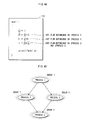
- the original program 110 is a sequential program executing the processes in the order from (Process 1) to (Process 5), as shown in FIG. 3.
- a sequential program includes processes related to each other in terms of a nonessential descriptive order when obtaining a calculation result.
- the descriptive order-related processes can produce the same calculation result as obtained in a sequential execution even if the execution order of the processes is changed. Furthermore, these processes are shared by multiple processors and executed in parallel. To detect descriptive order-related processes from a sequential program is called detection of parallelism.
- the program conversion unit 102 detects parallelism from the original program 110 as follows. In order to detect the parallelism, the program conversion unit 102 analyzes each process of the original program 110 from the beginning and examines whether there is data dependence.
- the instruction 1001-namely, (Process 2)- refers to the value of a variable a substituted in (Process 1), and therefore has a flow dependence on (Process 1).
- the flow dependence here means a relationship in which, for example, (Process 2) can be executed only after the execution of (Process 1).
- (Process 4) refers to the value of a variable b substituted in (Process 2) and the value of a variable c substituted in (Process 3), it has a flow dependence on (Process 2) and (Process 3).
- FIG. 4B shows an essential function structure of the original program 110, not the descriptive structure.
- (Process 2) or (Process 3) is executed after the execution of (Process 1). Since (Process 2) and (Process 3) are in a parallel relationship to each other, their execution order does not matter, and (Process 4) is executed after both (Process 2) and (Process 3) are executed.
- Process 1 is categorized as Group 1
- Process 2 as Group 2
- Process 3 as Group 3
- Process 4 as Group 4.
- the program conversion unit 102 generates an identity transformation in one or more groups among Groups 1 to 4.
- the identity transformation means a different process that produces the same calculation result.
- the program conversion unit 102 changes an operator used or adds a constant and/or a variable to thereby generate an identity transformation.
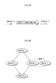
- the program conversion unit 102 generates, in Group 3, (Process 3') which is an identity transformation of (Process 3), as shown in FIG. 5A.
- (Process 3') is a process in which a is shifted two bits to the left, and has the same calculation result as that of a * 4 of (Process 3).
- FIG. 5B shows a function structure of the original program 110 after (Process 3') is generated as described above. As shown in the figure, in the original program 110 after the generation of (Process 3'), one process among (Process 2) and processes belonging to Group 3 is executed after the execution of (Process 1).
- the program conversion unit 102 generates a dummy process in one or more groups among Groups 1 to 4.
- the dummy process is a process that is inserted into the original program 110 in order to introduce complexity into the original program 110 and has no influence on a result output from the original program 110.
- the program conversion unit 102 generates, in Group 2, (Process 2') which is a dummy process of (Process 2), as shown in FIG. 6A.
- FIG. 6B shows a function structure of the original program 110 after (Process 2') is generated as described above.
- any one of the following is executed after the execution of (Process 1): one or more processes of Group 2, including (Process 2); (Process 3) of Group 3; and (Process 3') of Group 3.
- (Process 2) and one of (Process 3) and (Process 3') are executed, (Process 4) is executed.
- the dummy process (Process 2') may or may not be executed.
- the execution order among (Process 2), (Process 2'), and one of (Process 3) and (Process 3') does not matter.
- the program conversion unit 102 generates function data 120 by converting each of (Process 1), (Process 2), (Process 2'), (Process 3), (Process 3') and (Process 4) into a function.
- FIG. 7 shows the function data 120.
- the program conversion unit 102 incorporates variables used into a single structure 1011 called "struct val_t" in order to integrate the types of arguments, and converts (Process 1) into "funcA”, (Process 2) into “funcB”, (Process 3') into "funcC1", (Process 3) into “funcC”, (Process 4) into "funcD” and (Process 2') into “funcDummy” to thereby generate data 1012.
- the program conversion unit 102 sends the generated function data 120 and function structure to the program generation unit 104.
- the function structure is data used for determining the processing order of each function and generated by converting, for example, a function structure 250 shown in FIG. 17 into data. Note that there is no limitation to a data type of the function structure held by the program generation apparatus 10.
- FIG. 8 shows the function ID table 130.
- the function IDs of funcA, funcB, funcC, funcC1, funcD, and funcDummy are "0", “1", "5", "2", “4" and "3", respectively.
- the function ID assigning unit 103 sends the generated function ID table 130 to the program generation unit 104.
- the program generation unit 104 prestores therein function call program generation information.
- "while(!FuncSelector(&val));” 144 indicates updating val->n and performing loop iteration until FuncSelector returns "1".
- the function call program generation information is merely an example and not limited to this style.
- 145 indicates outputting a value of d when the loop of the while statement is finished.
- the program generation unit 104 writes the function data 120 to the function call program generation information to thereby generate the function call program 140 shown in FIG. 9.
- the program generation unit 104 prestores therein function call order-determining program generation information.
- 152 shows the following (Eq. 1).
- (Eq. 1) is an algorithm of a pseudo-random number generation called the linear congruential method, and is a recursive equation generating a random number sequence ⁇ X 0 , X 1 , X 2 , X 3 , ... ⁇ consisting of random numbers not less than 0 but less than m.
- (Eq. 1) is a recurrence equation generating a different random number sequence by changing the constant term b.
- the constant term b is referred to as the "initial value b".
- the program generation unit 104 writes a function name in "FuncSelector( )" to set “FuncSelector(struct val_t*a )".
- the program generation unit 104 determines the execution order of each function based on the function structure, and writes to the function call order-determining program generation information, a variable "f_a” storing whether funcA has been processed, a variable "f_b” storing whether funcB has been processed, and a variable "f_c” storing whether funcC or funcC1 has been processed. Since funcC and funcC1 are identity transformations, only one of them has to be processed, and therefore the same variable "f_c" is used.
- Each variable takes a value "0” or “1” with “0” indicating the function has not been processed and "1” indicating the function has been processed.
- the program generation unit 104 generates a switch statement 153 from the function ID table 130 and a function structure.
- case0 indicates a process to be executed when the value of x generated in 152 is "0".
- the program generation unit 104 processes funcA, then changes the variable f_a to "1", and returns "0" to the function call program 140.
- case1 indicates a process to be executed when the value of X generated in 152 is "1".
- the program generation unit 104 processes funcB, then changes the variable f_b to "1", and returns "0" to the function call program 140.
- case2 indicates a process to be executed when the value of x generated in 152 is "2".
- x 2
- the program generation unit 104 processes funcC1, then changes the variable f_c to "1", and returns "0" to the function call program 140.
- the program generation unit 104 determines from the function ID table 130 that a function having the function ID "3" is funcDumy, and writes case3:funcDummy(a);return(0); in the switch statement 153.
- case3 indicates a process executed when the value of x generated in 152 is "3".
- the program generation unit 104 executes funcDummy which is a dummy process, and returns "0".
- case4 indicates a process to be executed when the value of x generated in 152 is "4".
- x 4
- the program generation unit 104 processes funcD and returns "1" to the function call program 140.
- case5 indicates a process to be executed when the value of x generated in 152 is "5".
- the program generation unit 104 processes funcC, then changes the variable f_c to "1" , and returns "0" to the function call program 140.
- the program generation unit 104 writes default : return (0) in the function call order-determining program generation information. default indicates a process to be executed when none of case0 to case5 is satisfied. That is, when the value of x generated in 152 is none of 0, 1, 2, 3, 4, and 5, the program generation unit 104 returns "0" to the function call program 140.
- the program generation unit 104 sends to the compile/link unit 105, the function ID table 130 received from the function ID assigning unit 103, the generated function call program 140, and the generated function call order-determining program 150.
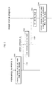
- the program conversion unit 102 reads the original program 110 stored in the original program storing unit 101, analyzes each process included in the read original program 110, and examines dependency of each process (Step S200).
- the program conversion unit 102 detects parallel processable portions based on the result of the dependency examination (Step S201).
- the program conversion unit 102 groups each process, and generates an identity transformation in one or more groups (Step S202).
- the program conversion unit 102 generates, in Group 3, (Process 3') which is an identity transformation of (Process 3).
- the program conversion unit 102 generates a dummy process in one or more groups (Step S203).
- the program conversion unit 102 generates, in Group 2, (Process 2') which is a dummy process of (Process 2).
- the program conversion unit 102 incorporates variables of (Process 1) to (Process 4) included in the original program 110 and variables of the identity transformation (Process 3') and the dummy process (Process 2') into a single structure, and converts each process into a function to thereby generate the function data 120 of FIG. 7 (Step S204) .
- the function ID assigning unit 103 assigns to each function converted by the program conversion unit 102, a function ID which uniquely identifies the function (Step S205), and generates the function ID table 130 of FIG. 8, composed of function names and function IDs (Step S206).
- the program generation unit 104 reads the function call order-determining program generation information (Step S211), and writes a function name in "FuncSelector ( )" of the read function call order determining generation information to set "FuncSelector(struct val_t*a)" (Step S212).
- the program generation unit 104 generates "case" for each of all function IDs included in the function ID table 130 (Step S214) . Specifically speaking, in the function ID table 130, function IDs from 0 to 5 and function names corresponding to the function IDs are written. The program generation unit 104 generates case 0 to case 5 shown in FIG. 10. Once generating cases corresponding to all the function IDs, the program generation unit 104 generates "default:return(0)" (Step S215) .
- the program generation unit 104 completes a switch statement by including cases and default generated in Steps S214 and S215, and includes the switch statement in the function call order-determining program generation information to thereby generate the function call order-determining program 150 of FIG. 10 (Step S216). Subsequently, the compile/line unit 105 compiles and links the function ID table 130, the function call program 140, and the function call order-determining program 150 to generate a program executable format (Step S217).
- the program execution unit 202 receives the program executable format from the reading unit 201 and stores it in the memory 203.
- the program execution unit 202 also calls the program executable format from the memory and executes it.
- the inside of the program execution unit 202 of FIG. 1 shows functional elements of the program execution unit 202.
- the program execution unit 202 is composed of: a program load unit 211; a table storage unit 212; a function call unit 213; and an execution unit 214. The following explains the program execution unit 202 based on these functional elements.
- the program load unit 211 instructs the reading unit 201 to read the program executable format from the storage apparatus 30, and receives the program executable format from the reading unit 201.
- the program load unit 211 loads into the memory 203, the function call program 140 and the function call order-determining program 150 in the received program executable format.
- the program load unit 211 also adds addresses, each of which indicates the position of a function included in the function call program 140 loaded into the memory 203, to the function ID table 130 received from the reading unit 201 and thereby generates a function ID table 220 shown in FIG. 12.
- the program load unit 211 stores the generated function ID table 220 in the table storage unit 212.
- the table storage unit 212 receives the function ID table 220 from the program load unit 211 and stores it therein.
- the function ID table 220 associates, for each function, a function name with a function ID and its position in the memory, as shown in FIG. 12. For example, an address indicating the position in the memory 203 where the function "funcA" identified by the function ID "0" is "0 ⁇ 07e9500".
- the function call unit 213 includes a call state storing unit, and stores the following information:
- the function call unit 213 assigns X 1 in (Eq. 1) to obtain X 2 .
- the function call unit 213 determines whether to execute a function having the function ID X 2 , based on each information of the call state storing unit.
- the function call unit 213 obtains a corresponding address from the function ID table 220, and calls the function from the memory 203 and sends this to the execution unit 214.
- the function call unit 213 changes a variable held by the call state storing unit, which indicates whether the function has been executed or not, to a state showing "executed".
- the function call unit 213 sequentially assigns X n in (Eq. 1) to obtain X n+1 .
- the function call unit 213 repeats the above process until funcD is called and executed. Once funcD is executed, the function call unit 213 ends the process. Note that, in the case where a function ID matching the obtained X n is not found in the function ID table 220, the function call unit 213 assigns X n in (Eq. 1), and discards X n after obtaining X n+1 .
- the execution unit 214 executes a function received from the function call unit 213.
- the function call unit 213 generates a random number (Step S303), and sets 0 to n (Step S304) .
- Step S307 When the function name obtained in Step S307 is funcDummy (YES in Step S308), the function call unit 213 proceeds to Step S312 and proceeds processing, whereas when the function name is not funcDummy (NO in Step S308), the function call unit 213 checks the call state (Step S309). Specifically speaking, the function call unit 213 judges whether the internal call state storing unit stores therein the same function name as one obtained in Step S307.
- Step S310 When the call state storing unit stores the same function name, which namely means that a function having the function name obtained in Step S307 has already processed (YES in Step S310), the function call unit 213 proceeds to Step S316 and proceeds processing.
- the call state storing unit does not store the same function name, which namely means that a function having the function name obtained in Step S307 has yet to be processed (NO in Step S310)
- the function call unit 213 checks the function structure of the call state storing unit.
- Step S307 When the processing order of the function name obtained in Step S307 is not correct (NO in Step S311), the function call unit 213 proceeds to Step S317 and proceeds processing.
- the function call unit 213 obtains, from the function ID table 220 stored in the table storage unit 212, an address of the function name obtained in Step S307-i.e. an address indicating the position, in the memory 203, of a function corresponding to the same function ID as X n obtained in Step S306 (Step S312).
- the function call unit 213 obtains the address "0 ⁇ 07e9500".
- the function call unit 213 calls a function from a position in the memory 203, indicated by the address obtained in Step S312 (Step S313), and sends the function to the execution unit 214.
- the execution unit 214 receives the function from the function call unit 213 and executes this (Step S314).
- the function call unit 213 stores the function name of the executed function in the call state storing unit as a processed function (Step S315).
- the function call unit 213 judges whether to end the process. In the case where all the functions have been processed, the function call unit 213 determines to end the process (YES in Step S316) and then ends the process. If there are unprocessed functions (NO in Step S316), the function call unit 213 sets n+1 to n (Step S317), returns to Step S306, and proceeds processing.
- a table of FIG. 15 shows specific examples of random number sequences obtained from (Eq. 1) included in the function call order-determining program 150 and (Eq. 2) included in the function call program 140 when the initial value b is changed.
- Table 240 of FIG. 16 shows specific examples of execution orders of functions in the case where the initial value b is changed.
- the function call unit 213 obtains, from the function ID table 220, the address "0 ⁇ 07e9500" of funcA whose function ID is 0, calls, from the memory 203, funcA in the position indicated by the obtained address, and sends this to the execution unit 214.
- the execution unit 214 executes funcA.
- the function call unit 213 determines, from the function ID table 220, a function whose function ID is 1 is funcB, and determines, from information stored in the call state storing unit, that funcB has yet to be executed. In addition, the function call unit 213 also determines from the information stored in the call state storing unit that the execution order is correct.
- the function call unit 213 obtains the address "0 ⁇ 07e9800" of funcB from the function ID table, and calls, from the memory 203, funcB in the position indicated by the obtained address and sends this to the execution unit 214.
- the execution unit 214 executes funcB.
- the function call unit 213 determines from the function ID table 220 that a function whose function ID is 4 is funcD. Since the information stored in the call state storing unit indicates that funcC or funcC1 has yet to be executed, the function call unit 213 determines that the execution order is incorrect.
- the function call unit 213 determines, from the function ID table 220, a function whose function ID is 5 is funcC, and determines, from information stored in the call state storing unit, that funcC has yet to be executed. In addition, the function call unit 213 also determines from the information stored in the call state storing unit that the execution order is correct.
- the function call unit 213 obtains the address "0 ⁇ 07e9900" of funcC from the function ID table, and calls, from the memory 203, funcC in the position indicated by the obtained address and sends this to the execution unit 214.
- the execution unit 214 executes funcC.
- the function call unit 213 determines, from the function ID table 220, a function whose function ID is 2 is funcC1. Since the information stored in the call state storing unit indicates that funcC has been executed, the function call unit 213 determines not to execute funcC1 here.
- the function call unit 213 obtains, from the function ID table 220, the address "0 ⁇ 07eb050" of funcDummy whose function ID is 3, and calls, from the memory 203, funcDummy in the position indicated by the obtained address and sends this to the execution unit 214.
- the execution unit 214 executes funcDummy.
- the function call unit 213 determines that funcA whose function ID is 0 has already been executed.
- the function call unit 213 determines that funcB whose function ID is 1 has already been executed.
- the function call unit 213 determines from the function ID table 220 that a function whose function ID is 4 is funcD. Since the information stored in the call state storing unit indicates that funcB and one of funcC and funcC1 have been executed, the function call unit 213 determines that the execution order is correct. The function call unit 213 obtains the address "0 ⁇ 07eb010" of funcD whose function ID is 4 from the function ID table 220, and calls, from the memory 203, funcD in the position indicated by the obtained address and sends this to the execution unit 214. The execution unit 214 executes funcD.
- the function call unit 213 obtains, from the function ID table 220, an address of funcDummy whose function ID is 3, and calls, from the memory 203, funcDummy in the position indicated by the obtained address and sends this to the execution unit 214.
- the execution unit 214 executes funcDummy.
- the function call unit 213 determines, from the function ID table 220, a function whose function ID is 2 is funcC1.
- the function call unit 213 determines, from the information stored in the call state storing unit, that both funcC1 and funcC have yet to be executed.
- the function call unit 213 also determines from the information stored in the call state storing unit that the execution order is correct.
- the function call unit 213 obtains the address of funcC1 from the function ID table 220, and calls, from the memory 203, funcC1 in the position indicated by the obtained address and sends this to the execution unit 214.
- the execution unit 214 executes funcC1.
- the function call unit 213 determines, from the function ID table 220, a function whose function ID is 5 is funcC. Since the information stored in the call state storing unit indicates that funcC1 has been executed, the function call unit 213 determines not to execute funcC here.
- the function call unit 213 determines from the function ID table 220 that a function whose function ID is 4 is funcD. Since the information stored in the call state storing unit indicates that funcB has yet to be executed, the function call unit 213 determines that the execution order is incorrect.
- the function call unit 213 determines, from the function ID table 220, a function whose function ID is 1 is funcB, and determines, from information stored in the call state storing unit, that funcB has yet to be executed. In addition, the function call unit 213 also determines from the information stored in the call state storing unit that the execution order is correct.
- the function call unit 213 obtains the address of funcB from the function ID table 220, and calls, from the memory 203, funcB in the position indicated by the obtained address and sends this to the execution unit 214.
- the execution unit 214 executes funcB.
- the function call unit 213 determines that funcA whose function ID is 0 has already been executed.
- the function call unit 213 obtains, from the function ID table 220, an address of funcDummy whose function ID is 3, and calls, from the memory 203, funcDummy in the position indicated by the obtained address and sends this to the execution unit 214.
- the execution unit 214 executes funcDumny.
- the function call unit 213 determines that funcC1 whose function ID is 2 has already been executed.
- the function call unit 213 determines, from the function ID table 220, a function whose function ID is 5 is funcC. Since the information stored in the call state storing unit indicates that funcC1 has been executed, the function call unit 213 determines not to execute funcC here.
- the function call unit 213 determines, from the function ID table 220, a function whose function ID is 4 is funcD. Since the information stored in the call state storing unit indicates that funcB and one of funcC or funcC1 have been executed, the function call unit 213 determines that the execution order is correct.
- the function call unit 213 obtains the address of funcD whose function ID is 4 from the function ID table 220, and calls, from the memory 203, funcD in the position indicated by the obtained address and sends this to the execution unit 214.
- the execution unit 214 executes funcD.
- the function call unit 213 determines processing of all functions is finished when funcD is executed, and ends the processing.
- funcA, funcDummy, funcC1 funcB, funcDummy, and funcD are executed in the stated order.
- funcA, funcC, funcDummy, funcB, funcDummy, and funcD are executed in the stated order.
- the program generation apparatus 10 may analyze an original program and generate a program executable format that decides the execution order of functions according to function groups created by grouping functions based on an attribute of each function included in the original program.
- the function structure 250 includes a sequential group 251, a parallel group 252, and an identity group 254.
- the sequential group 251 is composed of funcA 261, the parallel group 252 and funcD 266.
- the parallel group 252 is composed of a group 253 and the identity group 254.
- the identity group 254 is composed of funcC 264 and funcC1 265.
- the program generation apparatus 10 generates a function call program for executing the sequential group 251 in the following manner: 261, 252 and 266 are executed in the stated order; regarding the parallel group 252, the group 253 and the identity group 254 are executed in the order randomly decided at the execution; regarding the identity group 254, one of funcC 264 and funcC1 265 is randomly selected and executed; and funcDummy 263 is decided whether to be executed, and when funcDummy 263 is decided to be executed, it is then decided randomly at the execution how many times funcDummy 263 is to be executed.
- the program execution apparatus 20 executes the function call program generated by the program generation apparatus 10 and thereby executes functions in an order different for each execution.
- An information processing system 2 is explained next as the second embodiment of the present invention.
- the information processing system 2 is characterized by generating multiple execution path patterns at the generation of the program executable format, and selecting and executing one of the generated multiple execution path patterns at the execution of the program.
- the program generation apparatus 10a and program execution apparatus 20a are both computer systems similarly to the program generation apparatus 10 and program execution apparatus 20 of Embodiment 1, and the storage apparatus 30a is an optical disk.
- the program generation apparatus 10a generates a program executable format from an original program (S401), and subsequently generates an execution path pattern list (Step S402).
- the program generation apparatus 10a writes the generated program executable format and execution path pattern list to the storage apparatus 30a (Step S403).
- the storage apparatus 30a stores therein the program executable format and execution path pattern list (Step S404) .
- the program execution apparatus 20a reads a program executable format and an execution path pattern list from the storage apparatus 30a (Step S405).
- the program execution apparatus 20a selects an initial value from the execution path pattern list (Step S406), and executes each process of the program executable format in the order determined in accordance with the selected initial value (Step S407).
- the program generation apparatus 10a has a configuration in which the execution path pattern generation unit 107a is added to the program generation apparatus 10 of FIG. 1.
- the original program storing unit 101a, program conversion unit 102a, function ID assigning unit 103a, program generation unit 104a, compile/link unit 105a and writing unit 106a have the same functions as the original program storing unit 101, program conversion unit 102, function ID assigning unit 103, program generation unit 104, compile/link unit 105 and writing unit 106, individually.
- the original program storing unit 101a has the original program of FIG. 3, and the program conversion unit 102a converts the original program 110 to generate the function data 120 of FIG. 7.
- the function ID assigning unit 103a assigns an identifier to each function included in the function data 120 and generates the function ID table 130 of FIG. 8.
- the program generation unit 104a generates the function call program 140 of FIG. 9 and the function call order-determining program 150 of FIG. 10.
- the execution path pattern generation unit 107a is an component distinguishing the program generation apparatus 10a of the 2nd embodiment, as described above.
- the execution path pattern generation unit 107a generates an execution path pattern list.
- the execution path pattern generation unit 107a receives the function call program 140 and function call order-determining program 150 generated by the program generation unit 104a and outputs, to the compile/link unit 105a, the received function call program 140 and function call order-determining program 150 and the generated execution path pattern list.
- FIG. 20 shows a data configuration of an execution path pattern list 300.
- the execution path pattern list 300 is a specific example of an execution path pattern list generated by the execution path pattern generation unit 107a. As shown in the figure, the execution path pattern list 300 comprises four pieces of pattern information 301, 302, 303 and 304. Each pattern information piece includes an index, an execution path pattern value and a flag.
- the execution path pattern values each associated with an index is a random number generated by the execution path pattern generation unit 107a.
- the flags are set to either 0 or 1, where 0 indicates that the associated execution path pattern value has not been selected at the execution of the program execution format performed by the program execution apparatus 20a and 1 indicates that the associated execution path pattern value has already been selected.
- the compile/link unit 105a receives from the execution path pattern generation unit 107a, the function call program 140, the function call order-determining program 150 and the execution path pattern list. The compile/link unit 105a compiles and links these received programs and data to thereby generate a program executable format. The compile/link unit 105a outputs the generated program executable format to the writing unit106a.
- the writing unit 106a writes the program executable format output from the compile/link unit 105a to the storage apparatus 30a.
- the execution path pattern generation unit 107a of the program generation apparatus 10a decides the execution path pattern count N (Step S411).
- the execution path pattern count N a predetermined number prestored in the execution path pattern generation unit 107a may be used as N, or alternatively, a value input to an external input apparatus by the user may be received and used as N.
- the execution path pattern generation unit 107a sets the execution path pattern list therein (Step S412) .
- the column of the index includes numerical values from 0 to (N-1) in order beginning from the top of the column. In the column of the flag, 0 is written to all. The column of the execution path pattern value is blank with no data being written.
- the execution path pattern generation unit 107a judges whether the random number r generated in Step S414 has already been included in the execution path pattern values of the execution path pattern list (Step S415). In the case where r is included in the execution path pattern list (YES in Step S415), the execution path pattern generation unit 107a returns to Step S414 and proceeds processing. In the case where r is not included in the execution path pattern list (NO in Step S415), the execution path pattern generation 107a writes r into the execution path pattern list (Step S416).
- N represents the execution path pattern count decided in Step S411. In the case of 1 ⁇ N (NO in Step S418) , the execution path pattern generation 107a returns to Step S414 and proceeds processing.
- the execution path pattern generation unit 107a outputs the generated execution path pattern list to the compile/link unit 105a (Step S419).
- each component is the same as a counterpart of the program execution apparatus 20 of Embodiment 1.
- the program execution apparatus 20 disclosed in Embodiment 1 generates, at the execution of a program, a random number which is used as an initial value, and executes the program in the order decided in accordance with the initial value.
- the program execution apparatus 20a of the present embodiment selects, at the execution of a program, one execution path pattern value from the execution path pattern list of FIG. 20, which is used as an initial value, and executes the program in the order decided in accordance with the initial value.
- the reading unit 201a of the program execution apparatus 20a reads the function call program 140 and the function call order-determining program 150 from the storage apparatus 30a.
- the program load unit 211a loads into the memory 203a, the function call program 140 and function call order-determining program 150 read by the reading unit 201a (Step S431).
- the reading unit 201a reads the function ID table 130 from the storage apparatus 30a.
- the program load unit 211a stores addresses, each of which indicates the position of a function in the memory 203a, in the function ID table 130 (Step S432) to generate the function ID table 220 (FIG. 12).
- the table storage unit 212a stores therein the generated function ID table 220.
- the program execution apparatus 20a also reads the execution path pattern list 300 from the storage apparatus 30a and stores the read execution path pattern list 300 in the memory 203a.
- the function call unit 213a of the program execution unit 202a adds up values of flags, each of which is included in respective pattern information in the execution path pattern list 300, and sets the sum total as F (Step S433).
- the function call unit 213a judges whether F matches the execution path pattern value N (Step S434) .
- Step S434 the function call unit 213a resets all the flag values included in the respective pattern information in the execution path pattern list 300 to 0 (Step S435) . Subsequently, the function call unit 213a proceeds to Step S433 and proceeds processing.
- F # N NO in Step S434
- the function call unit 213a generates a random number R (Step S436), and specifies a value of R mod N as the index (Step S437).
- R mod N represents a remainder obtained by dividing R by N.
- the function call unit 213a reads, from the execution path pattern list 300 stored in the memory 203a, a flag value included in pattern information that has the specified index (Step S438) .
- Step S439 the function call unit 213a returns to Step S436 and proceeds processing.
- the function call unit 213a sets the flag value by changing from 0 to 1 (Step S440), reads an execution path pattern value associated with the specified index from the execution path pattern list 300 (Step S441), and sets the read execution path pattern value as r.
- the function call unit 213a obtains, from the function ID table 220 stored in the table storage unit 212a, a function name whose function ID is the same as X n acquired in Step S442 (Step S451) .
- the function call unit 213a proceeds to Step S456 and proceeds processing.
- the function call unit 213a checks the call state (Step S453) . Specifically speaking, the function call unit 213a judges whether the call state storing unit located internally has the same function name as one obtained in Step S451.
- the call state storing unit has the same information as one stored in the call state storing unit of the function call unit 213 in the program execution apparatus 20 of Embodiment 1.
- Step S454 the function call unit 213a proceeds to Step 460 and proceeds processing.
- the function call unit 213a checks the function structure of the call state storing unit.
- Step S451 When the processing order of the function name obtained in Step S451 is not correct (NO in Step S455) , the function call unit 213a proceeds to Step S461 and proceeds processing.
- the function call unit 213a obtains, from the function ID table 220 stored in the table storage unit 212a, an address of the function name obtained in Step S451-i.e. an address indicating the position, in the memory, of a function corresponding to the same function ID as X n obtained in Step S442 (Step S456) .
- the function call unit 213a calls a function from a position in the memory 203a, indicated by the address obtained in Step S456 (Step S457) , and sends the function to the execution unit 214a.
- the execution unit 214a receives the function from the function call unit 213a and executes this (Step S458) .
- the function call unit 213a stores the function name of the executed function in the call state storing unit as a processed function (Step S459) .
- the function call unit 213a judges whether to end the process (Step S460). In the case where all the functions have been processed, the function call unit 213a determines to end the process (YES in Step S460) and then ends the process. If there are unprocessed functions (NO in Step S460), the function call unit 213a sets n+1 to n (Step S461), returns to Step S442, and proceeds processing.
- An information processing system 3 is explained next as Embodiment 3 of the present invention.
- the information processing system 3 is characterized by generating a program executable format, testing the generated program executable format whether it operates appropriately, extracts multiple execution path patterns which operate appropriately, and selecting and executing one of the appropriately-operating execution path patterns at the execution of the program.
- the program generation apparatus 10b, program execution apparatus 20b, and program testing apparatus 40b are computer systems.
- the storage apparatuses 30b and 50b are optical disks.
- the program generation apparatus 10b has the same configuration and function as the program generation apparatus 10 (FIG. 1) disclosed in Embodiment 1.
- the program execution apparatus 20b has the same configuration and function as the program execution apparatus 20a disclosed in Embodiment 2.
- the program testing apparatus 40b is a component unique to Embodiment 3.
- the program testing apparatus 40b reads a program executable format from the storage apparatus 30b and executes this.
- the program testing apparatus 40b selects multiple execution path patterns which operate appropriately (Step S503), and generates an execution path pattern list (Step S504).
- the program testing apparatus 40b sends the program executable format and the execution pattern list to the program execution apparatus 20b via the storage apparatus 50b (Step S505).
- the program execution apparatus 20b reads the program executable format and execution path pattern list from the storage apparatus 50b.
- the program execution apparatus 20b selects an initial value from the execution path pattern list (Step S506), and executes each process of the program executable format in the order decided in accordance with the selected initial value (Step S507).
- the program generation apparatus 10b comprises an original program storing unit, a program conversion unit, a function ID assigning unit, a program conversion unit, a compile/link unit and a writing unit.
- the original program storing unit has the original program 110 shown in FIG. 3 and the execution results of the original program 110.
- the original program storing unit sends the original program 110 to the program conversion unit while sending the execution results of the original program 110 to the writing unit.
- the program conversion unit generates the function data 120 shown in FIG. 7 by converting the original program 110.
- the function ID assigning unit assigns an identifier to each function included in the function data 120 and generates the function ID table 130 of FIG. 8.
- the program generation unit generates the function call program 140 of FIG. 9 and the function call order-determining program 150 of FIG. 10.
- the compile/link unit receives the function call program 140 and function call order-determining program 150 from the program generation unit.
- the compile/link unit compiles and links these received programs and data to thereby generate a program executable format.
- the compile/link unit outputs the generated program executable format to the writing unit.
- the writing unit writes the program executable format output from the compile/link unit to the storage apparatus 30b. In addition, the writing unit writes to the storage apparatus 30b, the execution results of the original program 110 output from the original program storing unit.
- the program testing apparatus 40b has a configuration in which the execution path pattern generation unit 404b and writing unit 405b are added to the program execution apparatus 20 (FIG. 1) disclosed in Embodiment 1.
- the reading unit 401b reads the program executable format and the execution results of the original program 110 from the storage apparatus 30b, and sends the execution results to the execution path pattern generation unit 404b while sending the program executable format to the program load unit 411b.
- the program load unit 411b receives the program executable format from the reading unit 401b, and loads into the memory 403b, the function call program 140 and function call order-determining program 150 in the received program executable format.
- the program load unit 411b also adds addresses, each of which indicates the position of a function included in the function call program 140 loaded into the memory 403b, to the function ID table 130 and thereby generates the function ID table 220 shown in FIG. 12.
- the program load unit 411b stores the generated function ID table 220 in the table storage unit 412b.
- the table storage unit 412b receives the function ID table 220 from the program load unit 411b and stores it therein.
- the function call unit 413b has a call state storing unit, which stores therein the information described in the above embodiments.
- the function call unit 413b receives an initial value r from the execution path pattern generation unit 404b, calls functions from the memory 403b in the order decided in accordance with the received initial value r, and sends them to the execution unit 414b.
- the execution unit 414b executes functions received from the function call unit 413b. In addition, the execution unit 414b sends the execution results of the program to the execution path pattern generation unit 404b.
- the execution path pattern generation unit 404b has the same function as the execution path pattern generation unit 107a which is a component of the program generation apparatus 10a disclosed in Embodiment 2. That is, the execution path pattern generation unit 404b generates an execution path pattern list.
- the execution path pattern generation unit 404b differs from the execution path pattern generation unit 107a in comparing the result of the program executable format executed based on the generated execution path pattern and the execution result of the original program 110, and generates a list consisting only of execution path patterns with the two execution results that have been determined to match in the comparison.
- the execution path pattern generation unit 107a only generates multiple execution path patterns, and does not examine whether the generated execution path patterns individually matches the execution results of the original program 110.
- the execution path pattern generation unit 404b sends the generated execution path pattern list to the writing unit 405b.
- the writing unit 405b writes to the storage apparatus 50b, the execution path pattern list generated by the execution path pattern generation unit 404b and the program executable format stored in the memory 403b.
- the memory 403b is, specifically speaking, structured with RAM and ROM, and stores the function call program 140 and the function call order-determining program 150 written thereto by the program load unit 411b.
- the execution path pattern generation unit 404b decides the execution path pattern count N (Step S511).
- the execution path pattern generation unit 404b also obtains an execution result Vall of the original program 110 from the storage apparatus 30b via the reading unit 401b (Step S512).
- the execution path pattern generation unit 404b sets therein the execution path pattern list (Step S513).
- the column of the index includes numerical values from 0 to (N-1) in order beginning from the top of the column. In the column of the flag, 0 is written to all. The column of the execution path pattern value is blank with no data being written.
- the execution path pattern generation unit 404b judges whether the random number r generated in Step S515 has already included in the execution path pattern values of the execution path pattern list (Step S516) . In the case where r is included in the execution path pattern list (YES in Step S516), the execution path pattern generation unit 404b returns to Step S515 and proceeds processing. In the case where r is not included in the execution path pattern list (NO in Step S516), the program execution unit 402b performs the execution process of the program executable format using r as an initial value (Step S518).
- the execution path pattern generation unit 404b receives an execution result Val2 of the program executable format from the execution unit 414b (Step S518).
- the execution path pattern generation unit 404b compares the execution result vall of the original program 110 and the execution result Val2 of the program executable format performed using the initial value r (Step S519).
- Step S515 When Val1 ⁇ Val2 (NO in Step S519), the execution path pattern generation unit 404b returns to Step S515 and proceeds processing.
- Step S522 the execution path pattern generation 404b returns to Step S515 and proceeds processing.
- the execution path pattern generation unit 404b outputs the generated execution path pattern list to the writing unit 405b.
- each component of the program execution apparatus 20b is the same as a counterpart of the program execution apparatus 20a disclosed in Embodiment 2. That is, the program execution apparatus 20b selects one execution path pattern value from the execution path pattern list stored in the memory 203b at the execution of a program, uses the selected execution path pattern value as an initial value, and executes the program in the order decided in accordance with the initial value.
- a program 401 of FIG. 27A is structured by deleting funcA, funcB, funcC1 funcC, funcD and funcDummy from the function call program 140 of FIG. 9.
- a program 402 of FIG. 27B decides the call order, makes a jump with a got statement, and executes an instruction.
- a chaos function As a way of deciding the call order of functions, a chaos function, for example, may be used.
- a chaos function is characterized by behaving in a very complicated, irregular and unstable manner and making the estimation of the next state impossible, although it is based on a deterministic system where the entire subsequent states are principally decided once a state (i.e. initial value) at one point is decided.
- a cellular automaton for example, may be used to decide the call order of functions.
- a cellular automaton is a mathematical model in which discrete states change in discrete time steps according to a set regulation, and is characterized in that the state of n is decided from the initial value and the state of the neighborhood n-1.
- FIG. 28 is a flowchart showing a procedure of deciding function IDs using a cellular automaton.
- (a n 1 , a n 2 , a n 3 ) represents a state after a lapse of n from the initial value (a 0 1 , a 0 2 , a 0 3 ).
- Step S603 the procedure moves to Step S605.
- a n 1 calculated in Step S604 is set as a function ID (Step S605). All functions to be processed are called, and whether to end the procedure is judged. When it is determined to end the procedure (YES in Step S606), the function ID determining process using the cellular automaton is finished. When it is determined not to end the procedure (NO in Step S606), n is changed to n+1 (Step S607) and the procedure moves to Step S603 and is proceeded.
- a table 600 shown in FIG. 30 shows a specific example of the order of functions to be executed when each element is calculated as in the table 500 of FIG. 29 and a n 1 is the function ID.
- the program execution apparatus 20 may tell time at the execution and set b based on the time, or may read a value held in a specified storage area and set b based on the value.
- the program testing apparatus executes a program based on each initial value, and measures the execution time, which is a time period from the execution start to the end.
- the program testing apparatus may be configured so as to determine the execution is an inappropriate operation when the measured execution time is a predetermined time period or more, and to determine the execution is an appropriate operation when the execution time is less than the predetermined time.
- the program testing apparatus may make judgments of appropriate and inappropriate operations using the method shown in the above embodiments together with the method of measuring the execution time.
- these random number sequences are not generated by the program execution apparatus, but may be generated, in Embodiment 2, by the program generation apparatus and, in Embodiment 3, by the program testing apparatus
- the present invention may also be the computer program or digital signal to be transmitted via networks, as represented by telecommunications, wire/wireless communications, and the Internet, or via data broadcasting.
- the present invention may also be a computer system having a microprocessor and memory, wherein the memory stores the computer program and the microprocessor operates according to the computer program.
- the computer program or digital signal may be recorded on the above storage medium and transferred to an independent computer system, or alternatively, may be transferred to an independent computer system via the above network. Then, the independent computer system may execute the computer program or digital signal.
- the method for assembling integrated circuits is not limited to LSI, and a dedicated communication circuit or a general-purpose processor may be used to achieve this.
- a FPGA Field Programmable Gate Array
- a reconfigurable processor which allows reconfiguration of the connection and setting of circuit cells inside the LSI, may be used. If technology for forming integrated circuits that replaces LSIs is introduced, owing to advance in semiconductor technology or different technology derived therefrom, the integration of functional blocks may naturally be accomplished using such technology. There is also a possibility of application of biotechnology to the integrated circuit technology.
- the present invention includes a structure in which two or more of the above embodiments and modifications are combined.
- the present invention can be used as a mechanism for generating execution formats of programs difficult to be analyzed by users in industries which manufacture and sell apparatuses having therein programs undesirable to be analyzed by people other than authorized users.
Landscapes
- Engineering & Computer Science (AREA)
- Theoretical Computer Science (AREA)
- Software Systems (AREA)
- Technology Law (AREA)
- Computer Hardware Design (AREA)
- Computer Security & Cryptography (AREA)
- Physics & Mathematics (AREA)
- General Engineering & Computer Science (AREA)
- General Physics & Mathematics (AREA)
- Multimedia (AREA)
- Debugging And Monitoring (AREA)
- Devices For Executing Special Programs (AREA)
- Storage Device Security (AREA)
- Stored Programmes (AREA)
Applications Claiming Priority (2)
| Application Number | Priority Date | Filing Date | Title |
|---|---|---|---|
| JP2004190366 | 2004-06-28 | ||
| PCT/JP2005/011602 WO2006001365A1 (fr) | 2004-06-28 | 2005-06-24 | Dispositif de création de programme, dispositif de test de programme, dispositif d'exécution de programme, système de traitement des informations |
Publications (1)
| Publication Number | Publication Date |
|---|---|
| EP1758395A1 true EP1758395A1 (fr) | 2007-02-28 |
Family
ID=35781815
Family Applications (1)
| Application Number | Title | Priority Date | Filing Date |
|---|---|---|---|
| EP05765082A Withdrawn EP1758395A1 (fr) | 2004-06-28 | 2005-06-24 | Dispositif de création de programme, dispositif de test de programme, dispositif d'exécution de programme, système de traitement des informations |
Country Status (5)
| Country | Link |
|---|---|
| US (1) | US8307354B2 (fr) |
| EP (1) | EP1758395A1 (fr) |
| JP (1) | JP4783289B2 (fr) |
| CN (1) | CN1977531A (fr) |
| WO (1) | WO2006001365A1 (fr) |
Cited By (1)
| Publication number | Priority date | Publication date | Assignee | Title |
|---|---|---|---|---|
| WO2020193583A1 (fr) * | 2019-03-28 | 2020-10-01 | Banks And Acquirers International Holding | Procédé d'exécution de code sécurisé, dispositifs, système et programmes correspondants |
Families Citing this family (21)
| Publication number | Priority date | Publication date | Assignee | Title |
|---|---|---|---|---|
| WO2006115219A1 (fr) * | 2005-04-21 | 2006-11-02 | Matsushita Electric Industrial Co., Ltd. | Dispositif et procede rendant illisible un programme |
| WO2006115217A1 (fr) * | 2005-04-21 | 2006-11-02 | Matsushita Electric Industrial Co., Ltd. | Dispositif de conversion de programme et programme de conservation de secret |
| CN100565541C (zh) * | 2005-04-21 | 2009-12-02 | 松下电器产业株式会社 | 程序变换装置和变换方法 |
| US20080104704A1 (en) * | 2006-10-27 | 2008-05-01 | Ravikumar Mohandas | Security for physically unsecured software elements |
| JP5300294B2 (ja) | 2008-03-25 | 2013-09-25 | パナソニック株式会社 | 処理装置、難読化装置、プログラムおよび集積回路 |
| US8302210B2 (en) * | 2009-08-24 | 2012-10-30 | Apple Inc. | System and method for call path enforcement |
| CN102713839B (zh) * | 2009-10-08 | 2015-11-25 | 爱迪德技术有限公司 | 用于动态函数调用系统中的积极自我修改的系统和方法 |
| KR20140053756A (ko) | 2010-03-31 | 2014-05-08 | 어데토 캐나다 코포레이션 | 어플리케이션을 보호하기 위한 링크와 로드 방법 |
| KR101824044B1 (ko) * | 2011-05-17 | 2018-01-31 | 삼성전자주식회사 | 부호화 출력 기능을 구비한 데이터 저장 장치 및 시스템 |
| US8918768B2 (en) * | 2012-12-06 | 2014-12-23 | Apple Inc. | Methods and apparatus for correlation protected processing of data operations |
| US9721120B2 (en) | 2013-05-14 | 2017-08-01 | Apple Inc. | Preventing unauthorized calls to a protected function |
| US9633052B2 (en) * | 2013-05-17 | 2017-04-25 | Oracle International Corporation | System and method for decomposition of code generation into separate physical units though execution units |
| US8997060B2 (en) * | 2013-07-31 | 2015-03-31 | International Business Machines Corporation | Parallel program analysis and branch prediction |
| US9576116B2 (en) | 2013-12-26 | 2017-02-21 | Nxp B.V. | Secure software components anti-reverse-engineering by table interleaving |
| US9495111B2 (en) * | 2014-10-10 | 2016-11-15 | The Boeing Company | System and method for reducing information leakage from memory |
| DE102016119750B4 (de) * | 2015-10-26 | 2022-01-13 | Infineon Technologies Ag | Vorrichtungen und Verfahren zur Mehrkanalabtastung |
| JP6747104B2 (ja) * | 2016-06-30 | 2020-08-26 | オムロン株式会社 | セーフティシステム、プログラム、および方法 |
| US10082975B1 (en) | 2017-03-02 | 2018-09-25 | Micron Technology, Inc. | Obfuscation-enhanced memory encryption |
| JP7004938B2 (ja) | 2018-09-14 | 2022-01-21 | 富士通株式会社 | 最適化装置および最適化装置の制御方法 |
| JP7079711B2 (ja) * | 2018-10-17 | 2022-06-02 | Kddi株式会社 | 変換装置、変換方法、変換プログラム及び難読プログラム |
| US12153722B2 (en) * | 2020-12-23 | 2024-11-26 | Intel Corporation | Apparatus, systems, and methods to protect hardware and software |
Family Cites Families (11)
| Publication number | Priority date | Publication date | Assignee | Title |
|---|---|---|---|---|
| JPH0245829A (ja) | 1988-07-11 | 1990-02-15 | Intel Corp | 媒体に格納されているコンピュータプログラムウの無許可アクセスを検出する方法および回路 |
| US6668325B1 (en) * | 1997-06-09 | 2003-12-23 | Intertrust Technologies | Obfuscation techniques for enhancing software security |
| JP2000305453A (ja) * | 1999-04-21 | 2000-11-02 | Nec Corp | 暗号化装置,復号装置,および暗号化・復号装置 |
| US6594761B1 (en) * | 1999-06-09 | 2003-07-15 | Cloakware Corporation | Tamper resistant software encoding |
| US7080257B1 (en) * | 2000-03-27 | 2006-07-18 | Microsoft Corporation | Protecting digital goods using oblivious checking |
| JP2003330729A (ja) | 2002-05-14 | 2003-11-21 | Mitsubishi Electric Corp | コンパイラ装置 |
| JP3851228B2 (ja) * | 2002-06-14 | 2006-11-29 | 松下電器産業株式会社 | プロセッサ、プログラム変換装置及びプログラム変換方法、並びにコンピュータプログラム |
| US7254586B2 (en) * | 2002-06-28 | 2007-08-07 | Microsoft Corporation | Secure and opaque type library providing secure data protection of variables |
| US7584354B2 (en) * | 2003-01-31 | 2009-09-01 | Intel Corporation | Implementing portable content protection to secure secrets |
| US7340734B1 (en) * | 2003-08-27 | 2008-03-04 | Nvidia Corporation | Method and apparatus to make code more difficult to reverse engineer |
| US8220058B2 (en) * | 2003-09-25 | 2012-07-10 | Oracle America, Inc. | Rendering and encryption engine for application program obfuscation |
-
2005
- 2005-06-24 JP JP2006528614A patent/JP4783289B2/ja not_active Expired - Fee Related
- 2005-06-24 WO PCT/JP2005/011602 patent/WO2006001365A1/fr not_active Ceased
- 2005-06-24 CN CNA2005800215924A patent/CN1977531A/zh active Pending
- 2005-06-24 US US11/629,907 patent/US8307354B2/en active Active
- 2005-06-24 EP EP05765082A patent/EP1758395A1/fr not_active Withdrawn
Non-Patent Citations (1)
| Title |
|---|
| See references of WO2006001365A1 * |
Cited By (2)
| Publication number | Priority date | Publication date | Assignee | Title |
|---|---|---|---|---|
| WO2020193583A1 (fr) * | 2019-03-28 | 2020-10-01 | Banks And Acquirers International Holding | Procédé d'exécution de code sécurisé, dispositifs, système et programmes correspondants |
| FR3094515A1 (fr) * | 2019-03-28 | 2020-10-02 | Ingenico Group | procédé d’exécution de code sécurisé, dispositifs, système et programmes correspondants |
Also Published As
| Publication number | Publication date |
|---|---|
| US20080215862A1 (en) | 2008-09-04 |
| JP4783289B2 (ja) | 2011-09-28 |
| WO2006001365A1 (fr) | 2006-01-05 |
| JPWO2006001365A1 (ja) | 2008-04-24 |
| US8307354B2 (en) | 2012-11-06 |
| CN1977531A (zh) | 2007-06-06 |
Similar Documents
| Publication | Publication Date | Title |
|---|---|---|
| EP1758395A1 (fr) | Dispositif de création de programme, dispositif de test de programme, dispositif d'exécution de programme, système de traitement des informations | |
| US8392884B2 (en) | Test case automatic generation method for testing proactive GSM application on SIM cards | |
| US5819097A (en) | Industrial controller compiler with expandable instruction set | |
| US20080307006A1 (en) | File mutation method and system using file section information and mutation rules | |
| CN106547520B (zh) | 一种代码路径分析方法及装置 | |
| CN113031967B (zh) | 一种代码转换方法及装置 | |
| JP2012208830A (ja) | プログラムテスト装置、プログラムテスト方法、およびプログラム | |
| CN108985063A (zh) | 一种恶意代码混淆检测方法、系统、计算机设备、介质 | |
| CN112487421B (zh) | 基于异质网络的安卓恶意应用检测方法及系统 | |
| CN108664471A (zh) | 文字识别纠错方法、装置、设备及计算机可读存储介质 | |
| CN1983295A (zh) | 病毒识别方法及装置 | |
| US6678739B1 (en) | System, method, and computer program product for compressing test pattern set | |
| CN113778890A (zh) | 代码测试方法、装置、电子设备及存储介质 | |
| CN106919403B (zh) | 云环境下基于Java字节码的多粒度代码克隆检测方法 | |
| JP7243834B2 (ja) | ソフトウェア解析装置、ソフトウェア解析方法及びプログラム | |
| CN113805861B (zh) | 基于机器学习的代码生成方法、代码编辑系统及存储介质 | |
| CN113946804B (zh) | 一种源代码的混淆方法和装置 | |
| KR102174475B1 (ko) | 머신러닝을 이용하여 애플리케이션의 난독화 또는 패킹 여부를 식별하는 시스템과, 그것을 포함하는 은폐된 멀웨어 탐지 분류 시스템 및 방법 | |
| CN113050948A (zh) | 动态库优化方法、装置、设备及存储介质 | |
| CN113439271B (zh) | 受保护操作处理 | |
| CN116796321A (zh) | 一种二进制代码同源性分析方法、装置、设备及存储介质 | |
| KR100924519B1 (ko) | 소프트웨어 보안 테스팅을 수행하기 위한 알려지지 않은파일 포맷 분석 시스템 및 방법 | |
| CN112612471B (zh) | 代码处理方法、装置、设备及存储介质 | |
| KR102140714B1 (ko) | 안드로이드 애플리케이션의 주요부분을 패턴화한 멀웨어 탐지 분류 방법 및 시스템 | |
| CN113138923A (zh) | 通过分析修改代码确定测试范围的方法及装置 |
Legal Events
| Date | Code | Title | Description |
|---|---|---|---|
| PUAI | Public reference made under article 153(3) epc to a published international application that has entered the european phase |
Free format text: ORIGINAL CODE: 0009012 |
|
| 17P | Request for examination filed |
Effective date: 20061228 |
|
| AK | Designated contracting states |
Kind code of ref document: A1 Designated state(s): AT BE BG CH CY CZ DE DK EE ES FI FR GB GR HU IE IS IT LI LT LU MC NL PL PT RO SE SI SK TR |
|
| DAX | Request for extension of the european patent (deleted) | ||
| RAP1 | Party data changed (applicant data changed or rights of an application transferred) |
Owner name: PANASONIC CORPORATION |
|
| STAA | Information on the status of an ep patent application or granted ep patent |
Free format text: STATUS: THE APPLICATION HAS BEEN WITHDRAWN |
|
| 18W | Application withdrawn |
Effective date: 20090917 |