EP1758745B1 - Anordnung zur aufhängung einer blattfeder an einem fahrzeug - Google Patents
Anordnung zur aufhängung einer blattfeder an einem fahrzeug Download PDFInfo
- Publication number
- EP1758745B1 EP1758745B1 EP05752070A EP05752070A EP1758745B1 EP 1758745 B1 EP1758745 B1 EP 1758745B1 EP 05752070 A EP05752070 A EP 05752070A EP 05752070 A EP05752070 A EP 05752070A EP 1758745 B1 EP1758745 B1 EP 1758745B1
- Authority
- EP
- European Patent Office
- Prior art keywords
- vehicle
- leaf spring
- arrangement
- suspension means
- suspension
- Prior art date
- Legal status (The legal status is an assumption and is not a legal conclusion. Google has not performed a legal analysis and makes no representation as to the accuracy of the status listed.)
- Expired - Lifetime
Links
Images



Classifications
-
- B—PERFORMING OPERATIONS; TRANSPORTING
- B60—VEHICLES IN GENERAL
- B60G—VEHICLE SUSPENSION ARRANGEMENTS
- B60G11/00—Resilient suspensions characterised by arrangement, location or kind of springs
- B60G11/02—Resilient suspensions characterised by arrangement, location or kind of springs having leaf springs only
- B60G11/10—Resilient suspensions characterised by arrangement, location or kind of springs having leaf springs only characterised by means specially adapted for attaching the spring to axle or sprung part of the vehicle
- B60G11/12—Links, pins, or bushes
-
- B—PERFORMING OPERATIONS; TRANSPORTING
- B60—VEHICLES IN GENERAL
- B60G—VEHICLE SUSPENSION ARRANGEMENTS
- B60G17/00—Resilient suspensions having means for adjusting the spring or vibration-damper characteristics, for regulating the distance between a supporting surface and a sprung part of vehicle or for locking suspension during use to meet varying vehicular or surface conditions, e.g. due to speed or load
- B60G17/02—Spring characteristics, e.g. mechanical springs and mechanical adjusting means
- B60G17/023—Spring characteristics, e.g. mechanical springs and mechanical adjusting means the mechanical spring being a leaf spring
-
- B—PERFORMING OPERATIONS; TRANSPORTING
- B60—VEHICLES IN GENERAL
- B60G—VEHICLE SUSPENSION ARRANGEMENTS
- B60G2202/00—Indexing codes relating to the type of spring, damper or actuator
- B60G2202/10—Type of spring
- B60G2202/11—Leaf spring
- B60G2202/112—Leaf spring longitudinally arranged
-
- B—PERFORMING OPERATIONS; TRANSPORTING
- B60—VEHICLES IN GENERAL
- B60G—VEHICLE SUSPENSION ARRANGEMENTS
- B60G2204/00—Indexing codes related to suspensions per se or to auxiliary parts
- B60G2204/10—Mounting of suspension elements
- B60G2204/12—Mounting of springs or dampers
- B60G2204/121—Mounting of leaf springs
-
- B—PERFORMING OPERATIONS; TRANSPORTING
- B60—VEHICLES IN GENERAL
- B60G—VEHICLE SUSPENSION ARRANGEMENTS
- B60G2204/00—Indexing codes related to suspensions per se or to auxiliary parts
- B60G2204/40—Auxiliary suspension parts; Adjustment of suspensions
- B60G2204/421—Pivoted lever mechanisms for mounting suspension elements, e.g. Watt linkage
-
- B—PERFORMING OPERATIONS; TRANSPORTING
- B60—VEHICLES IN GENERAL
- B60G—VEHICLE SUSPENSION ARRANGEMENTS
- B60G2204/00—Indexing codes related to suspensions per se or to auxiliary parts
- B60G2204/40—Auxiliary suspension parts; Adjustment of suspensions
- B60G2204/422—Links for mounting suspension elements
-
- B—PERFORMING OPERATIONS; TRANSPORTING
- B60—VEHICLES IN GENERAL
- B60G—VEHICLE SUSPENSION ARRANGEMENTS
- B60G2204/00—Indexing codes related to suspensions per se or to auxiliary parts
- B60G2204/40—Auxiliary suspension parts; Adjustment of suspensions
- B60G2204/43—Fittings, brackets or knuckles
Definitions
- the present invention relates to an arrangement for suspending a leaf spring on a vehicle according to the preamble to patent claim 1 and to a leaf spring suspension device according to the preamble to patent claim 18.
- Leaf spring devices for the spring-loaded suspension of vehicle wheel axles are usually provided with a front and a rear mounting for suspension of a leaf spring assembly disposed between these mountings on a vehicle frame.
- the leaf spring assembly can be rotatably connected to the mountings.
- the rear mounting often comprises two pivot points and an intervening link which allows the leaf spring assembly to be displaced somewhat to the rear (and back again) along the longitudinal direction of the vehicle in the event of elastic deflection.
- the leaf spring assembly further has some form of means for coupling together the leaf spring and a vehicle wheel axle at a position situated between the front and rear mounting.
- leaf spring devices according to the prior art are described in generic US-B-6 209 897 or JP 61075005 .
- the front mounting of the leaf spring breaks and then the leaf spring assembly is bent away rearward in relation to the vehicle.
- Such a spring assembly which is connected to the vehicle frame by the rear mounting, does though have a relatively high bending resistance, so that the force which is needed during a collision to bend away and/or deform the spring assembly, which, during the collision, can also end up resting against other components of the vehicle, makes a not insubstantial contribution to the overall deformation characteristics of the vehicle.
- One object of the invention is to provide an arrangement of the type described in the introduction, which arrangement is more favorable with respect to its deformation characteristics should the arrangement be subjected to load during a collision.
- suspension means of the arrangement is provided with a built-in weakening 16 so as, in the event of a prespecified loading of the suspension means 3, and when the leaf spring 1 is connected to a vehicle 7 by means of the suspension means 3, to allow the suspension means 3 to collapse while the rear end 5 of the leaf spring 1 is moved rearward substantially past its, in normal running, rearmost position and/or is set free from the vehicle, means that the resistance from the leaf spring during a collision will be substantially reduced, which, in turn, can help to create a longer collision zone, for example in the front part of a truck.
- the invention also relates to a leaf spring device as claimed in patent claim 18.
- a truck provided with an inventive arrangement is illustrated in figure 1 .
- a leaf spring suspension device is disposed on the front wheel axle of the vehicle.
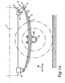
- the inventive arrangement for suspending a leaf spring 1 on a vehicle is illustrated in an enlarged view.
- leaf spring 1 is meant one or more leaves 2 made of a resilient material, such as steel, which have been coupled together to form a resilient unit.
- the arrangement comprises a means 3, which, at a first end 4, is connectable to a rear end 5 of a leaf spring 1 and, at a second end 6, is connectable to a vehicle, for example to a vehicle frame 7, for suspension of the leaf spring 1 on the vehicle.
- rear end 5 of a leaf spring 1 is meant the end which is disposed farthest back with respect to the normal direction of travel 30 of the vehicle.
- At the rear end 5 there is usually disposed one of normally two mountings 8, 9, disposed along the longitudinal direction of the vehicle, for the rotatable suspension of the leaf spring 1 on the vehicle.
- the inventive arrangement constitutes the rear mounting 9.
- the leaf spring 1 further has some form of means 35 for coupling together the leaf spring 1 and a vehicle wheel axle 11 at a position situated between the front 8 and the rear mounting 9.
- a rear mounting 90 configured according to the prior art is illustrated in figure 2 .
- the mounting 90 has a first component 120, which is fastened to a vehicle' frame 70 and which is provided with an axle journal 130 for rotatable suspension of the leaf spring 10.
- the first component 120 and the leaf spring 10 are connected by a link arm 140, which is disposed between the first axle journal 130 and a second axle journal 150 of the leaf spring 10.
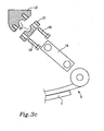
- FIG 3a , 3b and 3c an inventive arrangement is shown, in which the suspension means 3 is provided with a built-in weakening 16 so as, in the event of a prespecified loading of the suspension means 3, to allow the suspension means 3 to collapse.
- the suspension means 3 is provided with the built-in weakening 16 so as, in the event of said prespecified loading of the suspension means 3, and when the leaf spring 1 is connected to a vehicle, such as to a vehicle frame 7, by means of the suspension means 3, to allow the suspension means 3 to collapse while the rear end 5 of the leaf spring 1 is moved rearward substantially past its, in normal running, rearmost position and/or is set free from the vehicle 7.
- inventive suspension means 3 unlike the mounting 90 according to the prior art (illustrated in figure 2 ), is designed to collapse in a predictable manner should a prespecified force act upon the suspension means 3 in a prespecified direction.
- Such a suspension means 3 can contribute to a desired force transmission and a desired deformation zone in a vehicle on which the particular leaf spring 1 is disposed.
- the rear end 5 of the leaf spring 1 can therefore be moved to a position situated beyond the rearmost position which might be reached through the arrangement of a link arm 14 or corresponding component, and preferably the rear end 5 can be set free from the vehicle, so that the leaf spring 1, if the front mounting 8 breaks, can be moved rearward, while the rear mounting 9, and therefore the leaf spring 1 as a whole, makes no or only a minor contribution to the deformation strength of the vehicle in a collision.
- rearward movement is here meant, therefore, movement in a substantially opposite direction to the normal direction of travel 30 for a vehicle.
- the suspension means 3 preferably comprises a first component 12, which is connectable to the vehicle 7, and a second component 17, which is connectable to a rear end 5 of a leaf spring 1, and further comprises a member 18, which is arranged to connect the first 12 and second 17 component.
- the connecting member 18 is here arranged to collapse in the event of said prespecified load, so that the first 12 and second component 17 are separable from one another.
- the connecting member 18 is preferably a screw joint containing one or more screws 19, other connections might also be possible. For example, riveting, welding or some other joining method might be used to join the two components 12, 17 in the desired way.
- the arrangement can further comprise a first axle journal 13, which is preferably disposed between the first component 12 and the second component 17, a second axle journal 15 of the leaf spring 1, and a link arm 14 arranged to connect the second component 17 to the leaf spring 1 by the first and the second axle journal.
- the suspension means 3 can comprise such a link arm 14 for rotatable suspension of the leaf spring 1.
- suspension means 3 it is advantageous for the suspension means 3 to be adapted for suspension on a vehicle such that the interface between the first 12 and second component 17 has a principal extent in a plane 22 whose normal 23 has a component 24 directed horizontally rearward and a component 25 directed vertically downward in relation to the vehicle, see figure 3a .
- said horizontal component 24 is directed substantially parallel with the extent of the vehicle 7 in the longitudinal direction.
- the normal 23 can have a direction forming an angle ⁇ ranging from 0 to 60° in relation to a horizontal line 26 (which is parallel with the direction of travel 30 for the vehicle), and it preferably has a direction forming an angle ⁇ ranging from 20 to 45° in relation to the horizontal line 26.
- the suspension means 3 is preferably adapted to receive an axle journal 13 for force transmission between a vehicle 7 and a leaf spring 1.
- the connecting member 18 is arranged to hold together the first 12 and second component 17 so as to detain the axle journal 13 between the first 12 and second 17 component.
- the first component 12 and/or the second component 17 can be provided with a recess 27 for receiving the axle journal 13.
- Figure 3b illustrates, for the exemplification of the invention, forces F K , F D of an inventive suspension means 3 which is adapted to collapse upon application of a minimal force F K in a direction 20 which is substantially different than the vertical direction 21.
- the size of the force F K for which the suspension means 3 is adapted to collapse is less than the force F D which the suspension means 3 is capable of transmitting from a leaf spring 1 to the vehicle 7 in said principal force transmission direction 21.
- the suspension means 3 is in this case adapted to collapse upon application of a force F K in a direction substantially parallel, or almost parallel, with said normal 23 of the plane 22 between the first 12 and second 17 component upon application of a minimal force F K chosen from within the range 10-40 kN.
- the arrangement is further adapted for suspension of a front wheel axle on a truck for transmission of a force F D , from the rear end 5 of the leaf spring 1 to the vehicle 7, which force is of the order of magnitude 50 kN and is directed upward in the vertical direction 21.
- the invention also relates to a leaf spring suspension device for a vehicle, comprising a leaf spring 1 for spring-mounted suspension of a vehicle wheel axle 11, a front mounting 8 and a rear mounting 9 for suspension of the leaf spring 1 on a vehicle, for example on a vehicle frame 7.
- the rear mounting 9 comprises a suspension means 3, which is provided with a built-in weakening 16 so as, in the event of a prespecified loading of the suspension means 3, and when the leaf spring 1 is connected to a vehicle 7 by means of the suspension means 3, to allow the suspension means 3 to collapse while the rear end 5 of the leaf spring 1 is moved rearward substantially past its, in normal running, rearmost position and/or is set free from the vehicle 7.
- the suspension means 3 of the inventive leaf spring device can here be configured in accordance with that which is described above for the suspension means 3.
Landscapes
- Engineering & Computer Science (AREA)
- Mechanical Engineering (AREA)
- Vehicle Body Suspensions (AREA)
- Springs (AREA)
Claims (19)
- Anordnung zum Aufhängen einer Blattfeder (1) an einem Fahrzeug (7) mit einer Aufhängeeinrichtung (3), die an einem ersten Ende (4) mit einem hinteren Ende (5) der Blattfeder (1) und an einem zweiten Ende (6) mit dem Fahrzeug (7) für eine Aufhängung der Blattfeder (1) an dem Fahrzeug verbindbar ist, dadurch gekennzeichnet, dass die Aufhängeeinrichtung (3) mit einer eingebauten Schwächung (16) versehen ist, so dass im Falle einer vorbestimmten Belastung der Aufhängeeinrichtung (3) und wenn die Blattfeder (1) mit dem Fahrzeug (7) mit Hilfe der Aufhängeeinrichtung (3) verbunden ist, ein Kollabieren der Aufhängeeinrichtung (3) zugelassen wird, während das hintere Ende (6) der Blattfeder (1) nach hinten an ihrer bei Normalfahrt hintersten Stellung wesentlich vorbei bewegt und/oder frei vom Fahrzeug (7) gesetzt wird.
- Anordnung nach Anspruch 1, dadurch gekennzeichnet, dass die Aufhängeeinrichtung (3) eine erstes Bauteil (12), die mit dem Fahrzeug (7) verbindbar ist, ein zweites Bauteil (17), die mit dem hinteren Ende (5) der Blattfeder (1) verbindbar ist und ein Element (18) aufweist, das angeordnet ist, um das erste (12) und das zweite (17) Bauteil zu verbinden, wobei das Verbindungselement (18) für ein Kollabieren im Falle der vorbestimmten Belastung angeordnet ist, so dass das erste und zweite Bauteil (12.17) voneinander trennbar sind.
- Anordnung nach Anspruch 2, dadurch gekennzeichnet, dass das Verbindungselement (18) eine Schraubverbindung ist.
- Anordnung nach einem der vorhergehenden Ansprüche, dadurch gekennzeichnet, dass die Aufhängeeinrichtung (3) einen Verbindungsarm (14) für eine drehbare Aufhängung der Blattfeder (1) aufweist.
- Anordnung nach Anspruch 2 oder 3, dadurch gekennzeichnet, dass die Aufhängeeinrichtung (3) für ein solches Aufhängen an dem Fahrzeug (7) angepasst ist, dass die Trennfläche zwischen dem ersten (12) und dem zweiten (17) Bauteil eine Haupterstreckung in einer Ebene (22) hat, deren Normale (23) eine horizontal nach hinten gerichtete Komponente und eine vertikal nach unten bezogen auf das Fahrzeug (7) gerichtete Komponente (25) hat.
- Anordnung nach Anspruch 5, dadurch gekennzeichnet, dass die horizontale Komponente (24) im Wesentlichen parallel zu der Erstreckung des Fahrzeugs in der Längsrichtung gerichtet ist.
- Anordnung nach Anspruch 5 oder 6, dadurch gekennzeichnet, dass die Normale (23) eine solche Richtung hat, dass sie einen Winkel (α) bildet, der bezogen auf eine horizontale Linie (26) von 0° bis 60° reicht.
- Anordnung nach Anspruch 5 oder 6, dadurch gekennzeichnet, dass die Normale (23) eine solche Richtung hat, dass sie einen Winkel (α) bezogen auf eine horizontale Linie (26) bildet, der von 20 bis 45° reicht.
- Anordnung nach einem der Ansprüche 2 bis 8, dadurch gekennzeichnet, dass die Aufhängeeinrichtung (3) für die Aufnahme eines Achsenlagers (13) für die Kraftübertragung zwischen dem Fahrzeug (7) und der Blattfeder (1) angepasst ist, wobei das Verbindungselement (18) angeordnet ist, um in dem Fall, in welchem eine Belastung kleiner als die vorbestimmte Belastung ist, das erste Bauteil (12) und das zweite Bauteil (17) so zusammen zu halten, dass das Achsenlager (13) zwischen dem ersten und dem zweiten Bauteil (12, 17) festgehalten ist.
- Anordnung nach Anspruch 9, dadurch gekennzeichnet, dass das erste Bauteil (12) und/oder das zweite Bauteil (17) mit einer Aussparung (27) für die Aufnahme des Achsenlagers (13) versehen ist/sind.
- Anordnung nach Anspruch 4 und 9, dadurch gekennzeichnet, dass der Verbindungsarm (14) zwischen dem Lagerhals (13) und der Blattfeder (1) angeordnet ist.
- Anordnung nach einem der vorhergehenden Ansprüche, dadurch gekennzeichnet, dass die Aufhängeeinrichtung (3) für ein Kollabieren bei Anlegen einer Minimalkraft (FK) in eine Richtung (20) angepasst ist, die wesentlich anders als die Hauptkraftübertragungsrichtung (21) der Aufhängeeinrichtung (7) von der Blattfeder (1) zum Fahrzeug (7) ist.
- Anordnung nach Anspruch 12, dadurch gekennzeichnet, dass die Aufhängeeinrichtung (3) für ein Kollabieren bei Anlegen einer minimalen Kraft (FK) in eine Richtung (20) angepasst ist, die wesentlich anders als die Vertikalrichtung (21) ist.
- Anordnung nach Anspruch 12 oder 13, dadurch gekennzeichnet, dass die Größe der Kraft (FK) für die die Aufhängeeinrichtung (3) für ein Kollabieren angepasst ist, kleiner ist als die Kraft (FD), die die Aufhängeeinrichtung (3) von der Blattfeder (1) zum Fahrzeug (7) in der Hauptkraftübertragungsrichtung (21) übertragen kann.
- Anordnung nach einem der Ansprüche 5 bis 8, dadurch gekennzeichnet, dass die Aufhängeeinrichtung (3) für ein Kollabieren bei Anlegen einer Kraft (FK) in eine Richtung angepasst ist, die im Wesentlichen parallel oder fast parallel zu der erwähnten Normalen (23) ist.
- Anordnung nach einem der vorhergehenden Ansprüche, dadurch gekennzeichnet, dass die Aufhängeeinrichtung (3) für ein Kollabieren bei Anlegen einer minimalen Kraft (FK) angepasst ist, die innerhalb des Bereichs von 10 bis kN gewählt wird.
- Anordnung nach einem der vorhergehenden Ansprüche, dadurch gekennzeichnet, dass die Anordnung für die Aufhängung einer Vorderradachse (11) eines Lastkraftwagens angepasst ist.
- Blattfederaufhängungsvorrichtung für ein Fahrzeug mit einer Blattfeder (1) für eine federgehaltene Aufhängung einer Fahrzeugradachse (11) und mit einer vorderen und hinteren Halterung (8, 9) für die Aufhängung der Blattfeder (1) an dem Fahrzeug (7), dadurch gekennzeichnet, dass die hintere Haltung (8) eine Aufhängeeinrichtung (3) aufweist, die mit einer eingebauten Schwächung (16) versehen ist, so dass im Falle einer vorbestimmten Belastung der Aufhängeeinrichtung (3) und wenn die Blattfeder (1) mit dem Fahrzeug (7) mit Hilfe der Aufhängeeinrichtung (3) verbunden ist, ein Kollabieren der Aufhängeeinrichtung (3) zugelassen ist, während das hintere Ende (5) der Blattfeder (1) nach hinten an ihrer in normaler Fahrrichtung hintersten Position wesentlich vorbei bewegt und/oder von dem Fahrzeug (7) freigesetzt wird.
- Fahrzeug mit einer Anordnung nach einem der Ansprüche 1 bis 17.
Applications Claiming Priority (2)
| Application Number | Priority Date | Filing Date | Title |
|---|---|---|---|
| SE0401583A SE527302C2 (sv) | 2004-06-16 | 2004-06-16 | En anordning för upphängning av en bladfjäder hos ett fordon |
| PCT/SE2005/000889 WO2005123425A1 (en) | 2004-06-16 | 2005-06-10 | Arrangement for suspending a leaf spring on a vehicle |
Publications (2)
| Publication Number | Publication Date |
|---|---|
| EP1758745A1 EP1758745A1 (de) | 2007-03-07 |
| EP1758745B1 true EP1758745B1 (de) | 2008-06-11 |
Family
ID=32906822
Family Applications (1)
| Application Number | Title | Priority Date | Filing Date |
|---|---|---|---|
| EP05752070A Expired - Lifetime EP1758745B1 (de) | 2004-06-16 | 2005-06-10 | Anordnung zur aufhängung einer blattfeder an einem fahrzeug |
Country Status (8)
| Country | Link |
|---|---|
| US (1) | US20070090623A1 (de) |
| EP (1) | EP1758745B1 (de) |
| CN (1) | CN1968834B (de) |
| AT (1) | ATE398033T1 (de) |
| BR (1) | BRPI0512148A (de) |
| DE (1) | DE602005007490D1 (de) |
| SE (1) | SE527302C2 (de) |
| WO (1) | WO2005123425A1 (de) |
Families Citing this family (7)
| Publication number | Priority date | Publication date | Assignee | Title |
|---|---|---|---|---|
| JP5620755B2 (ja) * | 2010-08-31 | 2014-11-05 | 日野自動車株式会社 | サスペンション装置 |
| JP5735235B2 (ja) * | 2010-08-31 | 2015-06-17 | 日野自動車株式会社 | サスペンション装置 |
| CN105113472B (zh) * | 2015-09-09 | 2017-04-26 | 江苏佳佩环保机械设备有限公司 | 一种格栅清污机移动装置 |
| CN105501317B (zh) * | 2015-12-28 | 2018-02-13 | 勾长虹 | 基于行走系统可调的半挂车装置 |
| KR102506765B1 (ko) * | 2018-04-17 | 2023-03-07 | 현대자동차주식회사 | 리프스프링의 아이부 부시 장치 |
| EP4000971A1 (de) * | 2020-11-24 | 2022-05-25 | Volvo Truck Corporation | Verfahren und steuereinheit zur steuerung eines fahrgestellsystems in einem fahrzeug mit einer blattfeder |
| US11685486B2 (en) * | 2021-01-14 | 2023-06-27 | Saudi Arabian Oil Company | Resilient bumper and bumper system |
Family Cites Families (4)
| Publication number | Priority date | Publication date | Assignee | Title |
|---|---|---|---|---|
| US2063216A (en) * | 1932-11-30 | 1936-12-08 | Fed Spring Company | Resilient connection |
| GB427104A (en) * | 1933-10-12 | 1935-04-12 | Vernon Anthony Trier | Improvements in or relating to spring suspension apparatus for vehicles |
| GB2112496A (en) * | 1981-12-30 | 1983-07-20 | Leyland Vehicles | Vehicle suspension element |
| US6209897B1 (en) * | 1999-07-15 | 2001-04-03 | Paccar Inc | Apparatus and method for mounting a suspension system |
-
2004
- 2004-06-16 SE SE0401583A patent/SE527302C2/sv not_active IP Right Cessation
-
2005
- 2005-06-10 BR BRPI0512148-5A patent/BRPI0512148A/pt not_active IP Right Cessation
- 2005-06-10 WO PCT/SE2005/000889 patent/WO2005123425A1/en not_active Ceased
- 2005-06-10 DE DE602005007490T patent/DE602005007490D1/de not_active Expired - Lifetime
- 2005-06-10 EP EP05752070A patent/EP1758745B1/de not_active Expired - Lifetime
- 2005-06-10 AT AT05752070T patent/ATE398033T1/de not_active IP Right Cessation
- 2005-06-10 CN CN2005800201071A patent/CN1968834B/zh not_active Expired - Fee Related
-
2006
- 2006-12-18 US US11/612,463 patent/US20070090623A1/en not_active Abandoned
Also Published As
| Publication number | Publication date |
|---|---|
| DE602005007490D1 (de) | 2008-07-24 |
| CN1968834B (zh) | 2010-11-10 |
| CN1968834A (zh) | 2007-05-23 |
| EP1758745A1 (de) | 2007-03-07 |
| ATE398033T1 (de) | 2008-07-15 |
| SE0401583L (sv) | 2005-12-17 |
| SE0401583D0 (sv) | 2004-06-16 |
| WO2005123425A1 (en) | 2005-12-29 |
| US20070090623A1 (en) | 2007-04-26 |
| SE527302C2 (sv) | 2006-02-07 |
| BRPI0512148A (pt) | 2008-02-12 |
Similar Documents
| Publication | Publication Date | Title |
|---|---|---|
| EP3693201B1 (de) | Brennstoffzellenfahrzeug | |
| US7229088B2 (en) | Shackle assembly | |
| KR102174834B1 (ko) | 자동차 휠 서스펜션용 스프링 장치 | |
| JP5374588B2 (ja) | 中空軸−接続装置 | |
| US9944142B2 (en) | Wheel suspension for a vehicle axle | |
| US20180022388A1 (en) | Vehicle frame | |
| US20110079979A1 (en) | Vehicle suspension arm | |
| EP1667859B1 (de) | Lenkachsenaufhängung | |
| US5615906A (en) | Tandem axle suspension with leaf spring guided forward axle suspension and torque and torque beam guided rear axle suspension connected by a load equalizing bolster beam | |
| CN101242986A (zh) | 包括联接到侧梁的、形式为小型车架的空心体部的连接装置的支承机动车前端组件的结构以及相应的车辆 | |
| EP0825042A2 (de) | Vorrichtung zur Stabilisierung | |
| US20070090623A1 (en) | Arrangement for suspending a leaf spring on a vehicle | |
| US6789812B2 (en) | Vehicle antisway bar | |
| US20020030340A1 (en) | Automotive suspension system for increasing roll safety | |
| FR3041569A1 (fr) | Bras inferieur avec renfort fusible | |
| JP2018188039A (ja) | サスペンションアーム | |
| JP2010241349A (ja) | 車両用スタビライザバー取付機構 | |
| JP2018131137A (ja) | 車両の内装構造 | |
| US9725109B2 (en) | Steering column with decoupling J-slider | |
| EP0340738A2 (de) | Fahrzeugaufhängungssystem | |
| EP3480084A1 (de) | Anordnung eines lkw-fahrerhauses | |
| WO2015087441A1 (ja) | 車両のフレーム | |
| EP1182064A2 (de) | Fahrerhauslagerung | |
| CN212242967U (zh) | 离合踏板装置和具有它的车辆 | |
| US20090302592A1 (en) | Support structure for mounting on a frame of a vehicle |
Legal Events
| Date | Code | Title | Description |
|---|---|---|---|
| PUAI | Public reference made under article 153(3) epc to a published international application that has entered the european phase |
Free format text: ORIGINAL CODE: 0009012 |
|
| 17P | Request for examination filed |
Effective date: 20070116 |
|
| AK | Designated contracting states |
Kind code of ref document: A1 Designated state(s): AT BE BG CH CY CZ DE DK EE ES FI FR GB GR HU IE IS IT LI LT LU MC NL PL PT RO SE SI SK TR |
|
| 17Q | First examination report despatched |
Effective date: 20070702 |
|
| DAX | Request for extension of the european patent (deleted) | ||
| GRAP | Despatch of communication of intention to grant a patent |
Free format text: ORIGINAL CODE: EPIDOSNIGR1 |
|
| GRAS | Grant fee paid |
Free format text: ORIGINAL CODE: EPIDOSNIGR3 |
|
| RIN1 | Information on inventor provided before grant (corrected) |
Inventor name: SPRATLEY, LUIS Inventor name: PREIJERT, STEFAN |
|
| GRAA | (expected) grant |
Free format text: ORIGINAL CODE: 0009210 |
|
| AK | Designated contracting states |
Kind code of ref document: B1 Designated state(s): AT BE BG CH CY CZ DE DK EE ES FI FR GB GR HU IE IS IT LI LT LU MC NL PL PT RO SE SI SK TR |
|
| REG | Reference to a national code |
Ref country code: GB Ref legal event code: FG4D |
|
| REG | Reference to a national code |
Ref country code: CH Ref legal event code: EP |
|
| REF | Corresponds to: |
Ref document number: 602005007490 Country of ref document: DE Date of ref document: 20080724 Kind code of ref document: P |
|
| REG | Reference to a national code |
Ref country code: IE Ref legal event code: FG4D |
|
| REG | Reference to a national code |
Ref country code: SE Ref legal event code: TRGR |
|
| PG25 | Lapsed in a contracting state [announced via postgrant information from national office to epo] |
Ref country code: FI Free format text: LAPSE BECAUSE OF FAILURE TO SUBMIT A TRANSLATION OF THE DESCRIPTION OR TO PAY THE FEE WITHIN THE PRESCRIBED TIME-LIMIT Effective date: 20080611 Ref country code: SI Free format text: LAPSE BECAUSE OF FAILURE TO SUBMIT A TRANSLATION OF THE DESCRIPTION OR TO PAY THE FEE WITHIN THE PRESCRIBED TIME-LIMIT Effective date: 20080611 |
|
| PG25 | Lapsed in a contracting state [announced via postgrant information from national office to epo] |
Ref country code: PL Free format text: LAPSE BECAUSE OF FAILURE TO SUBMIT A TRANSLATION OF THE DESCRIPTION OR TO PAY THE FEE WITHIN THE PRESCRIBED TIME-LIMIT Effective date: 20080611 Ref country code: AT Free format text: LAPSE BECAUSE OF FAILURE TO SUBMIT A TRANSLATION OF THE DESCRIPTION OR TO PAY THE FEE WITHIN THE PRESCRIBED TIME-LIMIT Effective date: 20080611 |
|
| PG25 | Lapsed in a contracting state [announced via postgrant information from national office to epo] |
Ref country code: LT Free format text: LAPSE BECAUSE OF FAILURE TO SUBMIT A TRANSLATION OF THE DESCRIPTION OR TO PAY THE FEE WITHIN THE PRESCRIBED TIME-LIMIT Effective date: 20080611 Ref country code: IS Free format text: LAPSE BECAUSE OF FAILURE TO SUBMIT A TRANSLATION OF THE DESCRIPTION OR TO PAY THE FEE WITHIN THE PRESCRIBED TIME-LIMIT Effective date: 20081011 Ref country code: CZ Free format text: LAPSE BECAUSE OF FAILURE TO SUBMIT A TRANSLATION OF THE DESCRIPTION OR TO PAY THE FEE WITHIN THE PRESCRIBED TIME-LIMIT Effective date: 20080611 |
|
| PG25 | Lapsed in a contracting state [announced via postgrant information from national office to epo] |
Ref country code: SK Free format text: LAPSE BECAUSE OF FAILURE TO SUBMIT A TRANSLATION OF THE DESCRIPTION OR TO PAY THE FEE WITHIN THE PRESCRIBED TIME-LIMIT Effective date: 20080611 Ref country code: RO Free format text: LAPSE BECAUSE OF FAILURE TO SUBMIT A TRANSLATION OF THE DESCRIPTION OR TO PAY THE FEE WITHIN THE PRESCRIBED TIME-LIMIT Effective date: 20080611 Ref country code: PT Free format text: LAPSE BECAUSE OF FAILURE TO SUBMIT A TRANSLATION OF THE DESCRIPTION OR TO PAY THE FEE WITHIN THE PRESCRIBED TIME-LIMIT Effective date: 20081111 Ref country code: ES Free format text: LAPSE BECAUSE OF FAILURE TO SUBMIT A TRANSLATION OF THE DESCRIPTION OR TO PAY THE FEE WITHIN THE PRESCRIBED TIME-LIMIT Effective date: 20080922 Ref country code: BE Free format text: LAPSE BECAUSE OF FAILURE TO SUBMIT A TRANSLATION OF THE DESCRIPTION OR TO PAY THE FEE WITHIN THE PRESCRIBED TIME-LIMIT Effective date: 20080611 |
|
| PLBE | No opposition filed within time limit |
Free format text: ORIGINAL CODE: 0009261 |
|
| STAA | Information on the status of an ep patent application or granted ep patent |
Free format text: STATUS: NO OPPOSITION FILED WITHIN TIME LIMIT |
|
| PG25 | Lapsed in a contracting state [announced via postgrant information from national office to epo] |
Ref country code: EE Free format text: LAPSE BECAUSE OF FAILURE TO SUBMIT A TRANSLATION OF THE DESCRIPTION OR TO PAY THE FEE WITHIN THE PRESCRIBED TIME-LIMIT Effective date: 20080611 Ref country code: DK Free format text: LAPSE BECAUSE OF FAILURE TO SUBMIT A TRANSLATION OF THE DESCRIPTION OR TO PAY THE FEE WITHIN THE PRESCRIBED TIME-LIMIT Effective date: 20080611 Ref country code: BG Free format text: LAPSE BECAUSE OF FAILURE TO SUBMIT A TRANSLATION OF THE DESCRIPTION OR TO PAY THE FEE WITHIN THE PRESCRIBED TIME-LIMIT Effective date: 20080911 |
|
| 26N | No opposition filed |
Effective date: 20090312 |
|
| PG25 | Lapsed in a contracting state [announced via postgrant information from national office to epo] |
Ref country code: MC Free format text: LAPSE BECAUSE OF NON-PAYMENT OF DUE FEES Effective date: 20090630 |
|
| REG | Reference to a national code |
Ref country code: CH Ref legal event code: PL |
|
| REG | Reference to a national code |
Ref country code: IE Ref legal event code: MM4A |
|
| PG25 | Lapsed in a contracting state [announced via postgrant information from national office to epo] |
Ref country code: CH Free format text: LAPSE BECAUSE OF NON-PAYMENT OF DUE FEES Effective date: 20090630 Ref country code: LI Free format text: LAPSE BECAUSE OF NON-PAYMENT OF DUE FEES Effective date: 20090630 Ref country code: IE Free format text: LAPSE BECAUSE OF NON-PAYMENT OF DUE FEES Effective date: 20090610 |
|
| PG25 | Lapsed in a contracting state [announced via postgrant information from national office to epo] |
Ref country code: GR Free format text: LAPSE BECAUSE OF FAILURE TO SUBMIT A TRANSLATION OF THE DESCRIPTION OR TO PAY THE FEE WITHIN THE PRESCRIBED TIME-LIMIT Effective date: 20080912 |
|
| PG25 | Lapsed in a contracting state [announced via postgrant information from national office to epo] |
Ref country code: LU Free format text: LAPSE BECAUSE OF NON-PAYMENT OF DUE FEES Effective date: 20090610 |
|
| PG25 | Lapsed in a contracting state [announced via postgrant information from national office to epo] |
Ref country code: HU Free format text: LAPSE BECAUSE OF FAILURE TO SUBMIT A TRANSLATION OF THE DESCRIPTION OR TO PAY THE FEE WITHIN THE PRESCRIBED TIME-LIMIT Effective date: 20081212 |
|
| PG25 | Lapsed in a contracting state [announced via postgrant information from national office to epo] |
Ref country code: TR Free format text: LAPSE BECAUSE OF FAILURE TO SUBMIT A TRANSLATION OF THE DESCRIPTION OR TO PAY THE FEE WITHIN THE PRESCRIBED TIME-LIMIT Effective date: 20080611 |
|
| PG25 | Lapsed in a contracting state [announced via postgrant information from national office to epo] |
Ref country code: CY Free format text: LAPSE BECAUSE OF FAILURE TO SUBMIT A TRANSLATION OF THE DESCRIPTION OR TO PAY THE FEE WITHIN THE PRESCRIBED TIME-LIMIT Effective date: 20080611 |
|
| REG | Reference to a national code |
Ref country code: FR Ref legal event code: PLFP Year of fee payment: 11 |
|
| PGFP | Annual fee paid to national office [announced via postgrant information from national office to epo] |
Ref country code: GB Payment date: 20150604 Year of fee payment: 11 Ref country code: SE Payment date: 20150604 Year of fee payment: 11 |
|
| PGFP | Annual fee paid to national office [announced via postgrant information from national office to epo] |
Ref country code: IT Payment date: 20150618 Year of fee payment: 11 Ref country code: NL Payment date: 20150604 Year of fee payment: 11 |
|
| PGFP | Annual fee paid to national office [announced via postgrant information from national office to epo] |
Ref country code: FR Payment date: 20150630 Year of fee payment: 11 |
|
| REG | Reference to a national code |
Ref country code: SE Ref legal event code: EUG |
|
| REG | Reference to a national code |
Ref country code: NL Ref legal event code: MM Effective date: 20160701 |
|
| PG25 | Lapsed in a contracting state [announced via postgrant information from national office to epo] |
Ref country code: SE Free format text: LAPSE BECAUSE OF NON-PAYMENT OF DUE FEES Effective date: 20160611 |
|
| GBPC | Gb: european patent ceased through non-payment of renewal fee |
Effective date: 20160610 |
|
| REG | Reference to a national code |
Ref country code: FR Ref legal event code: ST Effective date: 20170228 |
|
| PG25 | Lapsed in a contracting state [announced via postgrant information from national office to epo] |
Ref country code: FR Free format text: LAPSE BECAUSE OF NON-PAYMENT OF DUE FEES Effective date: 20160630 |
|
| PG25 | Lapsed in a contracting state [announced via postgrant information from national office to epo] |
Ref country code: GB Free format text: LAPSE BECAUSE OF NON-PAYMENT OF DUE FEES Effective date: 20160610 Ref country code: NL Free format text: LAPSE BECAUSE OF NON-PAYMENT OF DUE FEES Effective date: 20160701 |
|
| PG25 | Lapsed in a contracting state [announced via postgrant information from national office to epo] |
Ref country code: IT Free format text: LAPSE BECAUSE OF NON-PAYMENT OF DUE FEES Effective date: 20160610 |
|
| PGFP | Annual fee paid to national office [announced via postgrant information from national office to epo] |
Ref country code: DE Payment date: 20180613 Year of fee payment: 14 |
|
| REG | Reference to a national code |
Ref country code: DE Ref legal event code: R119 Ref document number: 602005007490 Country of ref document: DE |
|
| PG25 | Lapsed in a contracting state [announced via postgrant information from national office to epo] |
Ref country code: DE Free format text: LAPSE BECAUSE OF NON-PAYMENT OF DUE FEES Effective date: 20200101 |