EP1759178B1 - Transducteur du type transducteur de vibrations - Google Patents
Transducteur du type transducteur de vibrations Download PDFInfo
- Publication number
- EP1759178B1 EP1759178B1 EP05754571.7A EP05754571A EP1759178B1 EP 1759178 B1 EP1759178 B1 EP 1759178B1 EP 05754571 A EP05754571 A EP 05754571A EP 1759178 B1 EP1759178 B1 EP 1759178B1
- Authority
- EP
- European Patent Office
- Prior art keywords
- measuring tube
- transducer
- support element
- vibration
- previous
- Prior art date
- Legal status (The legal status is an assumption and is not a legal conclusion. Google has not performed a legal analysis and makes no representation as to the accuracy of the status listed.)
- Expired - Lifetime
Links
Images




Classifications
-
- G—PHYSICS
- G01—MEASURING; TESTING
- G01F—MEASURING VOLUME, VOLUME FLOW, MASS FLOW OR LIQUID LEVEL; METERING BY VOLUME
- G01F1/00—Measuring the volume flow or mass flow of fluid or fluent solid material wherein the fluid passes through a meter in a continuous flow
- G01F1/76—Devices for measuring mass flow of a fluid or a fluent solid material
- G01F1/78—Direct mass flowmeters
- G01F1/80—Direct mass flowmeters operating by measuring pressure, force, momentum, or frequency of a fluid flow to which a rotational movement has been imparted
- G01F1/84—Coriolis or gyroscopic mass flowmeters
- G01F1/8409—Coriolis or gyroscopic mass flowmeters constructional details
-
- G—PHYSICS
- G01—MEASURING; TESTING
- G01F—MEASURING VOLUME, VOLUME FLOW, MASS FLOW OR LIQUID LEVEL; METERING BY VOLUME
- G01F1/00—Measuring the volume flow or mass flow of fluid or fluent solid material wherein the fluid passes through a meter in a continuous flow
- G01F1/76—Devices for measuring mass flow of a fluid or a fluent solid material
- G01F1/78—Direct mass flowmeters
- G01F1/80—Direct mass flowmeters operating by measuring pressure, force, momentum, or frequency of a fluid flow to which a rotational movement has been imparted
- G01F1/84—Coriolis or gyroscopic mass flowmeters
- G01F1/8409—Coriolis or gyroscopic mass flowmeters constructional details
- G01F1/8413—Coriolis or gyroscopic mass flowmeters constructional details means for influencing the flowmeter's motional or vibrational behaviour, e.g., conduit support or fixing means, or conduit attachments
-
- G—PHYSICS
- G01—MEASURING; TESTING
- G01F—MEASURING VOLUME, VOLUME FLOW, MASS FLOW OR LIQUID LEVEL; METERING BY VOLUME
- G01F1/00—Measuring the volume flow or mass flow of fluid or fluent solid material wherein the fluid passes through a meter in a continuous flow
- G01F1/76—Devices for measuring mass flow of a fluid or a fluent solid material
- G01F1/78—Direct mass flowmeters
- G01F1/80—Direct mass flowmeters operating by measuring pressure, force, momentum, or frequency of a fluid flow to which a rotational movement has been imparted
- G01F1/84—Coriolis or gyroscopic mass flowmeters
- G01F1/8409—Coriolis or gyroscopic mass flowmeters constructional details
- G01F1/8413—Coriolis or gyroscopic mass flowmeters constructional details means for influencing the flowmeter's motional or vibrational behaviour, e.g., conduit support or fixing means, or conduit attachments
- G01F1/8418—Coriolis or gyroscopic mass flowmeters constructional details means for influencing the flowmeter's motional or vibrational behaviour, e.g., conduit support or fixing means, or conduit attachments motion or vibration balancing means
-
- G—PHYSICS
- G01—MEASURING; TESTING
- G01F—MEASURING VOLUME, VOLUME FLOW, MASS FLOW OR LIQUID LEVEL; METERING BY VOLUME
- G01F1/00—Measuring the volume flow or mass flow of fluid or fluent solid material wherein the fluid passes through a meter in a continuous flow
- G01F1/76—Devices for measuring mass flow of a fluid or a fluent solid material
- G01F1/78—Direct mass flowmeters
- G01F1/80—Direct mass flowmeters operating by measuring pressure, force, momentum, or frequency of a fluid flow to which a rotational movement has been imparted
- G01F1/84—Coriolis or gyroscopic mass flowmeters
- G01F1/8409—Coriolis or gyroscopic mass flowmeters constructional details
- G01F1/8422—Coriolis or gyroscopic mass flowmeters constructional details exciters
-
- G—PHYSICS
- G01—MEASURING; TESTING
- G01F—MEASURING VOLUME, VOLUME FLOW, MASS FLOW OR LIQUID LEVEL; METERING BY VOLUME
- G01F1/00—Measuring the volume flow or mass flow of fluid or fluent solid material wherein the fluid passes through a meter in a continuous flow
- G01F1/76—Devices for measuring mass flow of a fluid or a fluent solid material
- G01F1/78—Direct mass flowmeters
- G01F1/80—Direct mass flowmeters operating by measuring pressure, force, momentum, or frequency of a fluid flow to which a rotational movement has been imparted
- G01F1/84—Coriolis or gyroscopic mass flowmeters
- G01F1/8409—Coriolis or gyroscopic mass flowmeters constructional details
- G01F1/8427—Coriolis or gyroscopic mass flowmeters constructional details detectors
-
- G—PHYSICS
- G01—MEASURING; TESTING
- G01F—MEASURING VOLUME, VOLUME FLOW, MASS FLOW OR LIQUID LEVEL; METERING BY VOLUME
- G01F1/00—Measuring the volume flow or mass flow of fluid or fluent solid material wherein the fluid passes through a meter in a continuous flow
- G01F1/76—Devices for measuring mass flow of a fluid or a fluent solid material
- G01F1/78—Direct mass flowmeters
- G01F1/80—Direct mass flowmeters operating by measuring pressure, force, momentum, or frequency of a fluid flow to which a rotational movement has been imparted
- G01F1/84—Coriolis or gyroscopic mass flowmeters
- G01F1/845—Coriolis or gyroscopic mass flowmeters arrangements of measuring means, e.g., of measuring conduits
- G01F1/8468—Coriolis or gyroscopic mass flowmeters arrangements of measuring means, e.g., of measuring conduits vibrating measuring conduits
- G01F1/8472—Coriolis or gyroscopic mass flowmeters arrangements of measuring means, e.g., of measuring conduits vibrating measuring conduits having curved measuring conduits, i.e. whereby the measuring conduits' curved center line lies within a plane
-
- G—PHYSICS
- G01—MEASURING; TESTING
- G01F—MEASURING VOLUME, VOLUME FLOW, MASS FLOW OR LIQUID LEVEL; METERING BY VOLUME
- G01F1/00—Measuring the volume flow or mass flow of fluid or fluent solid material wherein the fluid passes through a meter in a continuous flow
- G01F1/76—Devices for measuring mass flow of a fluid or a fluent solid material
- G01F1/78—Direct mass flowmeters
- G01F1/80—Direct mass flowmeters operating by measuring pressure, force, momentum, or frequency of a fluid flow to which a rotational movement has been imparted
- G01F1/84—Coriolis or gyroscopic mass flowmeters
- G01F1/845—Coriolis or gyroscopic mass flowmeters arrangements of measuring means, e.g., of measuring conduits
- G01F1/8468—Coriolis or gyroscopic mass flowmeters arrangements of measuring means, e.g., of measuring conduits vibrating measuring conduits
- G01F1/849—Coriolis or gyroscopic mass flowmeters arrangements of measuring means, e.g., of measuring conduits vibrating measuring conduits having straight measuring conduits
Definitions
- the invention relates to a vibration-type transducer suitable, in particular, for use in a Coriolis mass flowmeter.
- such measuring devices are often used, which cause Coriolis forces in the fluid by means of a transducer of the vibration type and an attached control and evaluation electronics and derived therefrom a measuring signal representing the mass flow produce.
- Vibrating measuring tubes of such sensors cause known - induced to lateral bending vibrations about an imaginary axis of vibration connecting the inlet end and the outlet end - in the fluid flowing Coriolis mechanism.
- the measuring tubes of such, for example, used in Coriolis mass flow meters transducers during operation at a momentary resonance frequency of a natural natural vibration form, esp. At constant-controlled oscillation amplitude, excited. Since this resonant frequency is especially dependent on the instantaneous density of the fluid, it is possible by means of commercially available Coriolis mass flowmeters In addition to the mass flow and the density of flowing fluids are measured.
- a major disadvantage of the above-described transducer is that due to mutual lateral deflections of the predominantly oscillating in Nutzmode single measuring tube gleichfrequent oscillating transverse forces can act on the pipeline and that these shear forces can be compensated independently only with a very high technical complexity of the density of the medium to be measured ,
- the inlet side and the outlet side acting on the pipe transverse forces include those in the EP-A 317 340 , of the US-A 53 98 554 , of the US-A 55 31 126 , of the US-A 56 91 485 , of the US Pat. No. 5,796,012 . US-A 59 79 246 or the
- WO-A 00 14 485 shown transducers each have at least one one-piece or multi-part counter-oscillator, which is fixed in each case on the inlet side and outlet side of the measuring tube.
- Such transducers with counteroscillators have esp. In such applications proven in which the fluid to be measured has a substantially constant or only to a very small extent variable density, ie in such applications in which acting on the connected pipe resulting from the The lateral forces generated by the measuring tube and the opposing forces generated by the counteroscillator can be set in advance to zero without further ado.
- the problem of density-dependent imbalances is in principle solved by adapting an amplitude response of the coupling elements or counter-oscillator to the measuring tube oscillations by means of variable spring stiffnesses dependent on the instantaneous oscillation amplitude such that the transverse forces generated by the vibrating measuring tube and counteroscillator are mutually different partially compensate.
- the disadvantage of the proposed transducer here is to be considered that despite technically very complex designs of the compensation mechanism a complete neutralization of the lateral forces generated by the measuring tube is neither practically nor theoretically possible.
- the invention consists in a transducer of the vibration type according to claim 1 or claim 2.
- the at least one coupling element is repeatedly subjected to elastic deformations due to relative movements of the oscillating measuring tube and the carrier element.
- the at least one coupling element measuring tube and carrier element connects resiliently together.
- the measuring tube in particular its oscillation shape in the excited oscillation mode, is substantially symmetrical, in particular rotationally symmetrical, with respect to an imaginary reference axis lying in the effective direction of the exciter force.
- the first support member has an effective also in the effective direction of the transverse force spring stiffness, which is different from the spring stiffness of the measuring tube, esp.
- the spring stiffness of the measuring tube is chosen lower than the spring stiffness of the first support member.
- the first support member is formed so that its mass is kept larger than a total mass of measuring tube with fluid contained therein.
- the excited oscillation mode essentially corresponds to a natural eigenmode of the measuring tube with the coupler arrangement acting on it.
- the vibrating measuring tube predominantly occupies a vibration mode with exactly three bending antinodes.
- an oscillation frequency of the bending oscillations of the measuring tube during operation is always kept lower than a lowest mechanical resonance frequency of the carrier element.
- the first carrier element extends at least in sections along the measuring tube.
- the measuring tube is at least partially enveloped by, in particular substantially tubular, formed first support member.
- the measuring tube and the first support member are mutually aligned substantially coaxially.
- the measuring tube communicates via a first connecting tube piece which opens into the inlet end and via a second connecting tube piece which leads into the outlet end, in particular aligned with the first connecting tube piece and / or with the oscillation axis.
- the first support member is formed as an inlet side and outlet side fixed to the measuring tube counter-oscillator and the measuring tube and the first support member via the first and the second connecting pipe piece vibrationally suspended in a, esp. Designed as a transducer housing, second support member ,
- Fig. 1 is a in a - not shown here - pipeline insertable measuring device for measuring at least one physical measurand - for example, a mass flow, m, a density, p, and / or a viscosity, ⁇ - a run in the pipeline, esp. flowing, fluid shown ,
- the measuring device comprises for this purpose a transducer of the vibration type which is flowed through during operation of the fluid to be measured.
- the transducer serves to generate in a fluid flowing through mechanical reaction forces, eg mass flow-dependent Coriolis forces, density-dependent inertial forces and / or viscosity-dependent frictional forces, the measurable, esp. Sensory detectable, act back on the transducer.
- the mass flow, m, the density, ⁇ , and / or the viscosity, ⁇ , of the fluid can be measured in the manner known to those skilled in the art.
- the mass flow, m, the density, ⁇ , and / or the viscosity, ⁇ of the fluid can be measured in the manner known to those skilled in the art.
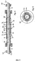
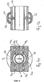
- the Fig. 2 to 6 Corresponding embodiments and embodiments of such vibration-type transducers are shown schematically.
- the transducer For guiding the fluid, the transducer comprises a single measuring tube 10 of a predeterminable measuring tube diameter, which is vibrated at least temporarily during operation and thus repeatedly, in particular cyclically, elastically deformed.
- the substantially smooth-walled, circular-cylindrical measuring tube 10 is supported for this purpose in a vibratable manner in a first support member 20 which is fixed in a suitably fixed manner on the inlet side and the outlet side.
- the first support member is tubular, esp. Coaxially aligned with the measuring tube 10, executed;
- the support member 20 may be formed, for example, as a transducer housing enclosing the measuring tube 10 and other components of the transducer.
- a support member 20 may instead of a support tube, for example, a in essential box-shaped support frame serve a. If necessary, but can also substantially along the measuring tube 10 extending support member 20, as well as in the EP-A 518,124 , of the US-A 57 05 754 or the US-A 62 23 605 shown to be formed as a solid support plate or as a box-shaped support frame. Further preferred embodiments of the carrier element 20 as well as other functions thereof will be explained in more detail below.
- a measuring tube 10 which is substantially straight in the process of being shown, it is also possible, in particular in a single plane, in particular S-shaped, for curved tubes, as used in the FIGS Fig.
- measuring tube 10 8 - 10 or eg in the DE-A 39 16 285 or EP-A 518,124 are shown, used as a measuring tube 10.
- An advantage of straight measuring tubes is, for example, that they can be emptied without leaving any residue in virtually any installation position, esp. Even after an in-line cleaning, with high security.
- measuring tubes are compared to a substantially omega-shaped or helically curved measuring tube much easier and therefore cheaper to produce.
- sensors with straight measuring tube usually have a comparison to sensors with curved measuring tube increased sensitivity to temperature fluctuations and concomitant axial length changes.
- measuring tube 10 For flowing the fluid through the measuring tube 10, as in the Fig. 2a . 3 or 8 to 10 shown, connected via an inlet side opening out the first connecting pipe section 11 and via an outlet-side opening second connecting pipe section 12 to the fluid supply and discharge, not shown here, pipeline.
- Measuring tube 10, inlet and outlet pipe section 11, 12 are aligned with each other and aligned to an imaginary longitudinal axis L, advantageously designed in one piece, so that for their production can serve as a single tubular semi-finished; if necessary, measuring tube 10 and pipe sections 11, 12 but also by means of individual, subsequently assembled, eg sixteengesch calendarter, semi-finished products can be produced.
- each of the two connecting pipe pieces 11, 12 is further formed in each case a flange 13 and 14, respectively; if necessary, the connecting pipe pieces 11, 12 but also directly to the pipeline, for example by means of welding or brazing, are connected.
- Fig. 1 In addition to the first support member 20, as well as from the synopsis of Fig. 1 . Fig. 2a and Fig. 3 or even from the Fig. 8 to 10 can be fixed to the connecting pipe pieces 11, 12, a second support member 100, which then, for example, instead of the first support member 20 as the measuring tube 10 receiving transducer housing can be configured, see. Fig. 1 ,
- the measuring tube 10 In operation of the transducer, the measuring tube 10 at least temporarily to bending vibrations, esp. In the range of a momentary natural natural frequency, so excited that in this excited vibration mode, the so-called Nutzmode, at least proportionately Bending oscillations around an inlet end and the outlet end of the measuring tube 10 imaginary connecting vibration axis performs. According to the invention, the measuring tube 10 is thereby excited to such a vibration mode in which it predominantly occupies a first vibration mode with at least three bending anti-vibration bellies. In other words, that natural natural vibration mode with three bending antinodes has the largest share in the instantaneous expression of the excited useful mode or its oscillation form.
- the first mode of vibration of the thus oscillating in the excited vibration mode, so predominantly three or more antinodes having, measuring tube 10 is substantially symmetrical, esp. Rotationally symmetrical, with respect to a direction of action of the excitation force, F exc , imaginary reference axis formed.
- the vibrating measuring tube 10 is deliberately excited so that it predominantly occupies a waveform with exactly three bending antinodes, that is, predominantly oscillates in the so-called f3 mode.
- Coriolis forces are thus induced by means of the measuring tube 10 vibrating in the manner described above in the fluid flowing therethrough. These in turn act on the measuring tube 10 and thus cause an additional, sensory detectable, not shown here, deformation of the measuring tube 10 according to a second waveform, which is coplanar and equal frequency superimposed on the excited Nutzmode of the straight measuring tube 10 here.
- the instantaneous manifestation of the deformation of the measuring tube 10 is, in particular, in terms of their amplitudes, of the instantaneous mass flow, m dependent.
- the so-called Coriolis mode e.g. serve a waveform with four antinodes or symmetrical waveforms with six or more antinodes.
- the transducer further comprises, in particular electrodynamic, exciter 40.
- This serves to one of a, not shown, control electronics fed, electrical excitation energy E exc , eg with a regulated current and / or a regulated Voltage, in one on the measuring tube 10, for example, pulse-shaped or harmonic, acting and this convert elastically deforming exciter force F exc in the manner described above.
- the excitation force F exc can here, as in Fig.
- energizing arrangement 40 for example, a plunger coil arrangement can be used, which has at least one cylindrical excitation coil attached to the measuring tube 10 or first support element 20, which is flowed through by a corresponding excitation current during operation, and a permanent magnet armature, which at least partially plunges into the exciter coil and which is located on the support element 20 on the measuring tube 10 is fixed.
- the exciter assembly 40 also, as in the US-A 45 24 610 shown to be realized by means of one or more electromagnets.
- the exciter assembly 40 such as in the WO-A 99 51 946 shown to realize by means of seismic pathogens.
- the transducer further comprises, in particular electrodynamic, sensor arrangement 50.
- the sensor arrangement 50 can be used, for example, a conventional sensor arrangement for such transducer, in which in the manner known to those skilled in at least one first sensor 51, Preferably, however, by means of a second sensor 52, the movements of the measuring tube 10, in particular on the inlet side and the outlet side, detected and converted into corresponding sensor signals S 1 , S 2 .
- sensors 51, 52 can, for example, as well as in Fig. 5 shown schematically, the vibrations of the measuring tube 10 and counter-oscillator 20 relatively measuring, electrodynamic velocity sensors or electrodynamic displacement sensors or acceleration sensors are used.
- measuring or optoelectronic sensor arrangements for detecting the vibrations of the measuring tube 10 can also be used by means of resistive or piezoelectric strain gauges.
- the sensor signals can be converted into the corresponding measured values in the manner known to the person skilled in the art by means of a corresponding, in particular digital, evaluation electronics.
- Both the above-mentioned control electronics for the exciter arrangement 40 and the evaluation electronics connected to the sensor arrangement 50 can be housed in an electronics housing 200, preferably attached to the converter housing 100.
- the exciter assembly 40 as well as in Fig. 3 and 4 shown, designed and arranged in the transducer so that it simultaneously, esp. Differentially, on measuring tube 10 and counter-oscillator 20 acts.
- the sensor assembly 50 may be designed and arranged in the transducer that the vibrations of measuring tube 10 and counter-oscillator 20 are detected differentially by them.
- the inner part is at least when using a straight measuring tube in an advantageous manner so that it is aligned with the two connecting pipe sections 11, 12 and at least partially within the measuring tube 10 lying first inertial main axis T 1 ; Vibration axis, Meßrohrlijnsachse L and inertial main axis T 1 are otherwise in in Fig. 3 shown embodiment practically coincident. Due to the laying of the center of mass MS of the inner part, esp.
- the operating modes assumed by the measuring tube 10 namely the above-mentioned bending oscillations in Nutz- and Coriolis mode, mechanically largely of possible torsional Vibrations of the measuring tube 10 about the main axis of inertia T 1 decoupled.
- This allows useful bending vibrations and useful torsional vibrations to be excited separately;
- disturbing torsional vibrations can equally effectively be separated from the bending vibrations in the useful and / or Coriolis mode.
- Both the relocation of the center of gravity MS and the first main axis of inertia T 1 toward the measuring tube longitudinal axis L can be considerably simplified, for example, that the inner part, ie measuring tube 10, support member 20 and the attached sensor and exciter assemblies 50, 40, formed and each other are arranged so that a mass distribution of the inner part along the MeßrohrlCodesachse L is substantially symmetrical, but at least invariant with respect to an imaginary rotation about the Meßrohrlticiansachse L by 180 ° (c2 symmetry), is.
- the here tubular, substantially coaxial with the measuring tube 10 arranged support member 20 is also formed largely axially symmetric with respect to the main axis of inertia T 1 , whereby the achievement of a symmetrical mass distribution of the inner part is considerably simplified and thus the center of mass MS in simple way is moved close to the Meßrohrlssensachse L out, see. Fig.
- the sensor and exciter assemblies 50, 40 are advantageously designed and arranged to each other on the measuring tube 10 and optionally on the counter-oscillator 20 that a mass moment of inertia generated by them is formed as concentric with the Meßrohrlssensachse L or at least kept as small as possible. This can be achieved, for example, by the fact that a common center of gravity of the sensor and exciter arrangement 50, 40 is likewise located as close as possible to the measuring tube longitudinal axis L and / or that a total mass of sensor and excitation arrangement 50, 40 is kept as small as possible.
- the exciter assembly 40 is designed for the purpose of separate Anrregung of torsional and / or bending vibrations of the measuring tube 10 or even for active braking of disturbing torsional vibrations and fixed to this and the counteroscillator 20 so that one of the bending vibrations generating force along an imaginary line of force acts on the measuring tube 10, which runs outside of a second inertial main axis T 2 perpendicular to the first main axis of inertia T 1 or intersects the latter in at most one point.
- the inner part is designed so that the second inertial main axis T 2 substantially coincides with the above-mentioned, in the effective direction of the excitation force, F exc , imaginary reference axis, see. Fig. 3 or 4 ,
- the exciter assembly 40 for this purpose at least one at least temporarily by the excitation current or a exciter subcurrent flowing through first exciter coil 41 a, which is fixed to a connected to the measuring tube 10 rigid lever 41 c and fixed on this and one from the outside on the counteroscillator 20 Armature 41 b differentially on the measuring tube 10 and the counteroscillator 20 acts.
- This arrangement also has the advantage that, on the one hand, the counter-oscillator 20 and thus also the transducer housing 100 are kept small in cross-section and nevertheless the exciter coil 41a, esp. Also during assembly, is easily accessible.
- the exciter assembly 40 has at least one arranged along a diameter of the measuring tube 10 second excitation coil 42a in the same manner as the exciter coil 41 a to the measuring tube 10 and the counteroscillator 20 is coupled.
- the exciter arrangement comprises two further excitation coils 43a, 44a, which are symmetrically arranged at least with respect to the second main axis of inertia T 2 , all of which are mounted in the transducer in the aforementioned manner.
- the outside of the second inertial main axis T 2 acting on the measuring tube 10 force can be generated by such two- or four-coil arrangements in a simple manner, for example, characterized in that one of the excitation coils, such as the exciter coil 41 a, a different inductance than the other or that one of the excitation coils, for example, the exciter coil 41 a, is traversed during operation of an exciter subcurrent, which is different from a respective exciter subcurrent of the respective other exciter coils.
- the sensor arrangement 50 comprises, as in Fig. 5 schematically illustrated, outside the second inertial main axis T 2 arranged on the measuring tube 10 fixed sensor coil 51 a.
- the sensor coil 51 a is as close as possible to an armature 51 b fixed to the counteroscillator 20 and magnetically coupled therewith in such a way that in the sensor coil a relative movement between the measuring tube 10 is changed by rotational and / or lateral relative position and / or relative distance and counter-oscillator 20 influenced, variable measuring voltage is induced. Due to the inventive arrangement of the sensor coil 51 a, both the above-mentioned torsional vibrations and the possibly excited bending vibrations can be detected in an advantageous manner at the same time. If necessary, however, the sensor coil 51a can do so also be fixed to the counter-oscillator 20 and in a corresponding manner the coupled thereto anchor 51 b on the measuring tube 10.
- the exciter assembly 40 and the sensor assembly 50 may be performed practically the same in their mechanical structure; Moreover, the aforementioned embodiments of the mechanical structure of the exciter assembly 40 can be transferred substantially to the mechanical structure of the sensor assembly 50 and vice versa.
- a conventional transducer of the type described would serve with a serving as a measuring tube 10 titanium tube having a nominal diameter of 18 mm, a wall thickness of about 1 mm and a length of about 660 mm and filled with water as a medium for the in Fig. 6 schematically shown f3-mode (dashed line) in about an oscillation frequency of 950 ... 1000 Hz and at a vibration amplitude of about 10 microns a resulting transverse force, Q 10 , as well Fig. 7 removable (dashed line), of a total of about 30 N result.
- a coupler arrangement 60 connected to measuring tube 10 and carrier element 20 is provided in the measuring transducer, which at least one with the vibrating measuring tube 10 and the support member 20 mechanically, esp. Spring-elastic, interacting first coupling element 61 comprises.
- the at least one coupling element 61 of the coupler arrangement 60 is in this case is mechanically coupled to the measuring tube 10 and the support member 20 so that it acts in a, esp. Central, area of one of the at least three antinodes on the measuring tube 10.
- the at least one coupling element 61 spring stiffness, c 60 the coupler assembly 60 to the effect.
- the measuring tube 10 is excited by means of the exciter assembly 40 so that the Nutzmode with the bending waveform mentioned above substantially corresponds to a natural eigenmode of the transducer, which essentially determined by the measuring tube 10 and the coupler 60 acting thereon is.
- the measuring tube 10 should oscillate in Nutzmode with a natural natural frequency, which is determined essentially by both the vibration characteristics of the measuring tube 10 with the fluid flowing through and by the vibration characteristics of the acting on the measuring tube 10 coupler assembly 60.
- the coupling element 61 may be, for example, essentially spring-elastic coupling elements with a positive spring constant, ie simple spiral or leaf springs or the like, which are fixed in a suitable manner both on the measuring tube 10 and on the carrier element 20.
- a positive spring constant ie simple spiral or leaf springs or the like
- those coupling elements which have an electrically adjustable negative spring constant, that is to say one or more magnetic coils through which a corresponding direct current flows, at least proportionally. this also the aforementioned US-A 55 31 126 ,
- the above-mentioned exciter arrangement with the exciter coils can simultaneously serve as a coupler arrangement.
- the at least one coupling element 61 is formed as a mechanical spring and, as in the Fig. 4a and 4b shown, also fixed to the one connected to the measuring tube 10 lever 41 c.
- the coupling element is also fixed directly on the counteroscillator.
- the coupling element is formed as a simple, possibly slightly curved in a plane, leaf spring, which is attached to a central portion of the lever 41 c, for example, as in Fig. 2a, b or 4 shown schematically, by soldering in a front side in the lever 41 c molded slot.
- a second, in particular to this substantially identical trained, second coupling element 62 is provided, which also acts in the region of one of the bending-Schwingungsbäuche of the measuring tube on this.
- the two coupling elements are arranged in the transducer so that the coupler assembly 60 is formed at least with respect to the above-mentioned, in the effective direction of the excitation force, F exc , imaginary reference axis is substantially symmetrical.
- the constant ⁇ is about 4000, while it is estimated to be about 600 for gauge tubes bent substantially S-shaped.
- the coupler assembly 60 then at least a 10-fold, using conventional materials and dimensions esp. To about a 20-fold, the Spring stiffness, c 10 , the measuring tube 10 is set.
- the application of the sizing rule in turn causes the spring stiffness, c 60
- the coupler arrangement at least a 0.8 times one in the effective direction of the transverse force, Q 0 , effective spring stiffness, c 10 , of the measuring tube 10 is set.
- the first carrier element 20 also has an effective spring stiffness, c 20 , in the effective direction of the transverse force, Q 0 , which is different from the spring stiffness, c 10 , of the measuring tube 10.
- the spring stiffness, c 10 , of the measuring tube 10 in a further advantageous embodiment of the invention, esp. By at least a 5-fold, lower than the spring stiffness, c 20 , the first support member 20.
- an oscillation frequency of the bending oscillations of the measuring tube 10 is selected so that it is always kept lower during operation, as a lowest mechanical resonance frequency of the support member 20th
- the rigid support member 20 is formed very heavy compared to the measuring tube 10. Accordingly, in this embodiment of the invention, a mass of the first support member 20 is selected so that a total mass of the measuring tube 10 with fluid contained therein is lower than this carrier element mass.
- Another advantage of the invention is also to be seen in the fact that the good results in terms of neutralization of the vibrating tube induced shear forces can surprisingly also be achieved when the measuring tube spanning, rigid first support member 20 and thus the entire sensor very easily are executed.
- the mass of the first support member 20 can also be chosen so that the total mass of the measuring tube 10 with contained therein Fluid is higher than this carrier element mass.
- a rigid and equally lightweight support element can when in Fig. 3 shown embodiment can be achieved in a simple manner, for example by laterally attached to the tubular support member 20 rod or bar-shaped reinforcements extending substantially parallel to the Meßrohrlticiansachse L.
- Another possibility for creating a comparatively lightweight, but also very rigid support member 20 is the use of appropriate materials with a high modulus of elasticity and a low density, such as glass, ceramic, glass ceramic, reinforced with glass and / or carbon fibers plastic or similar.
- the vibration characteristics additionally possibly - simultaneously or alternately - excited useful torsional oscillations around the above-mentioned inlet and outlet end of the measuring tube imaginarily connecting vibration axis, as for example in the case of transducers according to the US-B 68 40 109 can be stimulated, hardly influenced.
- the coupler arrangement 60 according to the invention is preferably to be designed so that a resultant line of action of all the spring forces generated by them substantially with the above-mentioned, in the effective direction of the excitation force, F exc , lying imaginary reference axis coincided.
- the coupler assembly 60 is also to be designed so that a distribution of all the spring forces generated by it is formed substantially symmetrically with respect to the aforesaid reference axis.
Landscapes
- Physics & Mathematics (AREA)
- Fluid Mechanics (AREA)
- General Physics & Mathematics (AREA)
- Measuring Volume Flow (AREA)
Claims (17)
- Transducteur du type à vibrations destiné à un fluide s'écoulant dans une conduite, lequel transducteur comprend :- un tube de mesure (10) vibrant au moins temporairement en fonctionnement, placé dans le cours de la conduite et destiné à guider le fluide- un premier élément support (20) fixé en une extrémité d'entrée et en une extrémité de sortie du tube de mesure (10),- un circuit d'excitation électromécanique (40) destiné à générer une force d'excitation, Fexc, variable dans le temps, faisant entrer en vibration le tube de mesure (10),- un circuit capteur (50) destiné à mesurer les vibrations du tube de mesure (10), ainsi que- un dispositif coupleur (60) relié avec le tube de mesure (10) et l'élément support (20), lequel dispositif coupleur comprend au moins un élément de couplage (61) interagissant mécaniquement, notamment de façon élastique, avec le tube de mesure (10) vibrant et l'élément support (20),- pour lequel le tube de mesure (10) est excité au moins temporairement, en fonctionnement, en un mode de vibration au moyen du circuit d'excitation (40), mode dans lequel il exécute au moins partiellement des vibrations de flexion autour d'un axe de vibration reliant de façon imaginaire l'extrémité d'entrée et l'extrémité de sortie du tube de mesure (10), de telle manière qu'il adopte pour l'essentiel une forme de vibration avec au moins trois ventres de vibration de flexion,- pour lequel l'au moins un élément de couplage (61) du dispositif coupleur (60) est couplé mécaniquement avec le tube de mesure (10) et l'élément support (20) de telle sorte à agir sur le tube de mesure (10) dans une zone, notamment centrale, de l'un des au moins trois ventres de vibration,- pour lequel le tube de mesure (10) est pour l'essentiel droit, et- pour lequel une rigidité élastique, c60, notamment pour l'essentiel constante, du dispositif coupleur (60), déterminée par l'au moins un élément de couplage (61), agissant entre le tube de mesure (10) et l'élément support (20), est supérieure à 0,5 fois, notamment dans la plage de 0,7 à 1,3 fois, un rapport, Q10/x0, qui représente une force transversale, Q10, se rapportant à une déviation latérale, X10, d'un point d'attaque, initiée globalement par le tube de mesure (10) vibrant côté entrée et côté sortie dans l'élément support (20) et/ou dans la conduite raccordée, point d'attaque au niveau duquel le dispositif coupleur (60) agit sur le tube de mesure (10), de telle sorte que la rigidité élastique du dispositif coupleur (60) est réglée à au moins 10 fois, notamment à au moins 20 fois, par rapport à une rigidité élastique, c10, agissant dans la direction d'action de la force transversale, Q10, du tube de mesure (10).
- Transducteur du type à vibrations destiné à un fluide s'écoulant dans une conduite, lequel transducteur comprend :- un tube de mesure (10) vibrant au moins temporairement en fonctionnement, placé dans le cours de la conduite et est destiné à guider le fluide- un premier élément support (20) fixé en une extrémité d'entrée et en une extrémité de sortie du tube de mesure (10),- un circuit d'excitation électromécanique (40) destiné à générer une force d'excitation, Fexc, variable dans le temps, faisant entrer en vibration le tube de mesure (10),- un circuit capteur (50) destiné à mesurer les vibrations du tube de mesure (10), ainsi que- un dispositif coupleur (60) relié avec le tube de mesure (10) et l'élément support (20), lequel dispositif coupleur comprend au moins un élément de couplage (61) interagissant mécaniquement, notamment de façon élastique, avec le tube de mesure (10) vibrant et l'élément support (20),- pour lequel le tube de mesure (10) est excité au moins temporairement, en fonctionnement, en un mode de vibration au moyen du circuit d'excitation (40), mode dans lequel il exécute au moins partiellement des vibrations de flexion autour d'un axe de vibration reliant de façon imaginaire l'extrémité d'entrée et l'extrémité de sortie du tube de mesure (10), de telle manière qu'il adopte pour l'essentiel une forme de vibration avec au moins trois ventres de vibration de flexion,- pour lequel l'au moins un élément de couplage (61) du dispositif coupleur (60) est couplé mécaniquement avec le tube de mesure (10) et l'élément support (20) de telle sorte à agir sur le tube de mesure (10) dans une zone, notamment centrale, de l'un des au moins trois ventres de vibration,- pour lequel le tube de mesure (10) est pour l'essentiel coudé, notamment pour l'essentiel coudé en forme de S, et- pour lequel une rigidité élastique, c60, notamment pour l'essentiel constante, du dispositif coupleur (60), déterminée par l'au moins un élément de couplage (61), agissant entre le tube de mesure (10) et l'élément support (20), est supérieure à 0,5 fois, notamment dans la plage de 0,7 à 1,3 fois, un rapport, Q10/x0, qui représente une force transversale, Q10, se rapportant à une déviation latérale, X10, d'un point d'attaque, initiée globalement par le tube de mesure (10) vibrant côté entrée et côté sortie dans l'élément support (20) et/ou dans la conduite raccordée, point d'attaque au niveau duquel le dispositif coupleur (60) agit sur le tube de mesure (10), de telle sorte que la rigidité élastique du dispositif coupleur (60) est réglée à au moins 0,8 fois par rapport à une rigidité élastique, c10, agissant dans la direction d'action de la force transversale, Q10, du tube de mesure (10).
- Transducteur selon la revendication 1 ou 2,- pour lequel le tube de mesure (10) est excité, en fonctionnement, au moyen d'un circuit d'excitation (40), au moins temporairement en un mode de vibration dans lequel il exécute au moins partiellement des vibrations torsionnelles autour de l'axe de vibration, ce même axe reliant pour l'essentiel de façon imaginaire l'extrémité d'entrée et l'extrémité de sortie du tube de mesure (10), et- pour lequel les éléments de couplage (61, 62) sont exécutés en tant que ressorts à lames, qui sont reliés à travers un levier (41 c) avec le tube de mesure (10).
- Transducteur selon l'une des revendications précédentes, pour lequel l'au moins un élément de couplage est soumis, en fonctionnement, de façon répétée à des déformations élastiques, en raison de mouvements relatifs du tube de mesure (10) vibrant et de l'élément support (20).
- Transducteur selon la revendication précédente, pour lequel l'au moins un élément de couplage (61) relie de façon élastique entre eux le tube de mesure (10) et l'élément support (20).
- Transducteur selon l'une des revendications précédentes, pour lequel le tube de mesure (10), notamment sa forme de vibration dans le mode de vibration excité, est pour l'essentiel symétrique, notamment en symétrie de révolution, par rapport à un axe de référence imaginaire situé dans la direction d'action de la force d'excitation, Fexc.
- Transducteur selon l'une des revendications précédentes, pour lequel le premier élément support (20) présente une rigidité élastique, c20, agissant également dans la direction d'action de la force transversale, Q10, laquelle rigidité est différente de la rigidité élastique, c10, du tube de mesure (10).
- Transducteur selon la revendication précédente, pour lequel la rigidité élastique, c10, du tube de mesure (10) est choisie inférieure à la rigidité élastique, c20, du premier élément support (20).
- Transducteur selon l'une des revendications précédentes, pour lequel une masse totale du tube de mesure (10), avec le fluide qu'il contient, est choisie inférieure à une masse du premier élément support.
- Transducteur selon l'une des revendications précédentes, pour lequel le mode de vibration excité correspond pour l'essentiel à un mode propre naturel du tube de mesure (10) avec le dispositif coupleur (60) agissant sur ce mode.
- Transducteur selon la revendication précédente, pour lequel le tube de mesure (10) vibrant adopte pour l'essentiel une forme de vibration avec exactement trois ventres de vibration de flexion.
- Transducteur selon l'une des revendications précédentes, pour lequel la fréquence des vibrations de flexion du tube de mesure (10), en fonctionnement, est toujours maintenue plus basse qu'une fréquence de résonance mécanique inférieure de l'élément support (20).
- Transducteur selon l'une des revendications précédentes, pour lequel le premier élément support (20) s'étend au moins partiellement le long du tube de mesure (10).
- Transducteur selon la revendication précédente, pour lequel le tube de mesure (10) est entouré au moins partiellement par le premier élément support (20) qui est pour l'essentiel de forme tubulaire.
- Transducteur selon la revendication précédente, pour lequel le tube de mesure (10) et le premier élément support (20) sont alignés entre eux pour l'essentiel de façon coaxiale.
- Transducteur selon l'une des revendications précédentes, pour lequel le tube de mesure (10) communique avec la conduite par l'intermédiaire d'un premier élément de tube de liaison (11) débouchant dans l'extrémité d'entrée et par l'intermédiaire d'un deuxième élément de tube de liaison (12) débouchant dans l'extrémité de sortie et notamment aligné par rapport au premier élément de tube de liaison (11) et/ou par rapport à l'axe de vibration.
- Transducteur selon la revendication précédente, pour lequel le premier élément support (20) est conçu en tant que contre-vibrateur (20) fixé côté entrée et côté sortie au tube de mesure (10), et pour lequel le tube de mesure et le premier élément support (20) sont suspendus de façon apte à vibrer dans un deuxième élément support (100) conçu notamment en tant que boîtier de transmetteur, par l'intermédiaire du premier et du deuxième élément de tube de liaison (11, 12).
Applications Claiming Priority (2)
| Application Number | Priority Date | Filing Date | Title |
|---|---|---|---|
| DE200410030392 DE102004030392A1 (de) | 2004-06-23 | 2004-06-23 | Meßwandler vom Vibrationstyp |
| PCT/EP2005/052817 WO2006000540A1 (fr) | 2004-06-23 | 2005-06-17 | Transducteur du type transducteur de vibrations |
Publications (2)
| Publication Number | Publication Date |
|---|---|
| EP1759178A1 EP1759178A1 (fr) | 2007-03-07 |
| EP1759178B1 true EP1759178B1 (fr) | 2017-08-09 |
Family
ID=35033713
Family Applications (1)
| Application Number | Title | Priority Date | Filing Date |
|---|---|---|---|
| EP05754571.7A Expired - Lifetime EP1759178B1 (fr) | 2004-06-23 | 2005-06-17 | Transducteur du type transducteur de vibrations |
Country Status (4)
| Country | Link |
|---|---|
| EP (1) | EP1759178B1 (fr) |
| DE (1) | DE102004030392A1 (fr) |
| DK (1) | DK1759178T3 (fr) |
| WO (1) | WO2006000540A1 (fr) |
Families Citing this family (18)
| Publication number | Priority date | Publication date | Assignee | Title |
|---|---|---|---|---|
| DE102005054855A1 (de) * | 2005-11-15 | 2007-05-16 | Flowtec Ag | Meßwandler vom Vibrationstyp |
| US7472607B2 (en) | 2005-11-15 | 2009-01-06 | Endress + Hauser Flowtec Ag | Measurement transducer of vibration type |
| US7490521B2 (en) | 2005-11-15 | 2009-02-17 | Endress + Hauser Flowtec Ag | Measurement transducer of vibration type |
| US7475603B2 (en) | 2005-11-15 | 2009-01-13 | Endress + Hauser Flowtec Ag | Measurement transducer of vibration-type |
| US8299015B2 (en) | 2006-07-25 | 2012-10-30 | Lipoxen Technologies Limited | Derivatisation of granulocyte colony-stimulating factor |
| DE102006062220A1 (de) * | 2006-12-22 | 2008-06-26 | Endress + Hauser Flowtec Ag | Meßwandler vom Vibrationstyp |
| DE102006062219A1 (de) * | 2006-12-22 | 2008-06-26 | Endress + Hauser Flowtec Ag | Meßwandler vom Vibrationstyp |
| DE102006062185A1 (de) * | 2006-12-22 | 2008-06-26 | Endress + Hauser Flowtec Ag | Meßwandler vom Vibrationstyp |
| DE102007050686A1 (de) * | 2007-10-22 | 2009-04-23 | Endress + Hauser Flowtec Ag | Meßwandler vom Vibrationstyp |
| DE102007062397A1 (de) * | 2007-12-20 | 2009-06-25 | Endress + Hauser Flowtec Ag | Meßwandler vom Vibrationstyp |
| DE102008035877A1 (de) * | 2008-08-01 | 2010-02-04 | Endress + Hauser Flowtec Ag | Meßwandler vom Vibrationstyp |
| US8336396B2 (en) * | 2009-03-11 | 2012-12-25 | Endress + Hauser Flowtec Ag | Measuring transducer of vibration-type, as well as an in-line measuring device having such a measuring transducer |
| DE102009060834B4 (de) * | 2009-12-29 | 2012-11-29 | Krohne Ag | Coriolis-Massedurchflussmessgerät |
| CN104995490B (zh) | 2012-12-30 | 2018-10-16 | 恩德斯+豪斯流量技术股份有限公司 | 振动型测量变换器以及形成有该测量变换器的测量系统 |
| EP2938972B1 (fr) * | 2012-12-30 | 2023-05-31 | Endress+Hauser Flowtec AG | Transducteur de type vibratoire ainsi que système de mesure formé avec celui-ci |
| WO2015130963A2 (fr) | 2014-02-27 | 2015-09-03 | Xenetic Biosciences, Inc. | Compositions et méthodes d'administration au cerveau de protéine insuline ou insulinoïde |
| WO2020099513A1 (fr) | 2018-11-13 | 2020-05-22 | Lipoxen Technologies Limited | Glyco-polysialylation de blinatumomab |
| CN110736454B (zh) * | 2019-11-15 | 2024-01-12 | 上海交通大学 | 适用于角速度测量的装置及测量方法 |
Family Cites Families (9)
| Publication number | Priority date | Publication date | Assignee | Title |
|---|---|---|---|---|
| US4109524A (en) * | 1975-06-30 | 1978-08-29 | S & F Associates | Method and apparatus for mass flow rate measurement |
| EP0759542B1 (fr) * | 1995-08-21 | 2004-11-10 | Oval Corporation | Débitmètre à effet Coriolis |
| US5979246A (en) * | 1998-02-09 | 1999-11-09 | Micro Motion, Inc. | Spring rate balancing of the flow tube and a balance bar in a straight tube Coriolis flowmeter |
| BR9912981B1 (pt) * | 1998-08-31 | 2012-01-10 | método e aparelho para um medidor de fluxo coriolis possuindo seu fator de calibragem do fluxo independente da densidade do material. | |
| DE19840782C2 (de) * | 1998-09-08 | 2001-09-06 | Krohne Messtechnik Kg | Massendurchflußmeßgerät |
| US6439060B1 (en) * | 1999-10-14 | 2002-08-27 | Fmc Technologies, Inc. | Dynamic counterbalance for Coriolis mass flowmeters |
| DE10020606A1 (de) * | 2000-04-27 | 2001-10-31 | Flowtec Ag | Vibrations-Meßgerät und Verfahren zum Messen einer Viskosität eines Fluids |
| US6487917B1 (en) * | 2000-05-02 | 2002-12-03 | Micro Motion, Inc. | Low thermal stress balance bar for a coriolis flowmeter |
| US6666098B2 (en) * | 2001-05-23 | 2003-12-23 | Endress + Hauser Flowtec Ag | Vibratory transducer |
-
2004
- 2004-06-23 DE DE200410030392 patent/DE102004030392A1/de not_active Withdrawn
-
2005
- 2005-06-17 WO PCT/EP2005/052817 patent/WO2006000540A1/fr not_active Ceased
- 2005-06-17 DK DK05754571.7T patent/DK1759178T3/en active
- 2005-06-17 EP EP05754571.7A patent/EP1759178B1/fr not_active Expired - Lifetime
Non-Patent Citations (1)
| Title |
|---|
| None * |
Also Published As
| Publication number | Publication date |
|---|---|
| DK1759178T3 (en) | 2017-10-09 |
| WO2006000540A1 (fr) | 2006-01-05 |
| EP1759178A1 (fr) | 2007-03-07 |
| DE102004030392A1 (de) | 2006-01-19 |
Similar Documents
| Publication | Publication Date | Title |
|---|---|---|
| EP1502085B1 (fr) | Transformateur de mesure de type a vibrations | |
| EP2122311B1 (fr) | Transducteur de mesure du type à vibrations | |
| EP1389300B1 (fr) | Transducteur de vibrations | |
| EP1381830B1 (fr) | Transducteur de mesure de type vibratoire | |
| EP1759178B1 (fr) | Transducteur du type transducteur de vibrations | |
| DE102007062397A1 (de) | Meßwandler vom Vibrationstyp | |
| DE102008035877A1 (de) | Meßwandler vom Vibrationstyp | |
| EP2201337B1 (fr) | Transducteur de vibrations | |
| DE10235322A1 (de) | Meßwandler vom Vibrationstyp | |
| DE10220827A1 (de) | Messwandler vom Vibrationstyp | |
| DE102005062007A1 (de) | Meßwandler vom Vibrationstyp | |
| EP1949048B1 (fr) | Convertisseur de mesure du type a vibrations | |
| EP1963793B1 (fr) | Convertisseur de mesure du type a vibrations | |
| DE102005062004A1 (de) | Meßwandler vom Vibrationstyp | |
| EP1223412B1 (fr) | Débitmètre massique de Coriolis monotubulaire courbé avec dispositif d'excitation symétrique | |
| DE102006062185A1 (de) | Meßwandler vom Vibrationstyp | |
| DE102006062219A1 (de) | Meßwandler vom Vibrationstyp |
Legal Events
| Date | Code | Title | Description |
|---|---|---|---|
| PUAI | Public reference made under article 153(3) epc to a published international application that has entered the european phase |
Free format text: ORIGINAL CODE: 0009012 |
|
| 17P | Request for examination filed |
Effective date: 20061213 |
|
| AK | Designated contracting states |
Kind code of ref document: A1 Designated state(s): AT BE BG CH CY CZ DE DK EE ES FI FR GB GR HU IE IS IT LI LT LU MC NL PL PT RO SE SI SK TR |
|
| DAX | Request for extension of the european patent (deleted) | ||
| 17Q | First examination report despatched |
Effective date: 20150915 |
|
| GRAP | Despatch of communication of intention to grant a patent |
Free format text: ORIGINAL CODE: EPIDOSNIGR1 |
|
| INTG | Intention to grant announced |
Effective date: 20170216 |
|
| GRAS | Grant fee paid |
Free format text: ORIGINAL CODE: EPIDOSNIGR3 |
|
| GRAA | (expected) grant |
Free format text: ORIGINAL CODE: 0009210 |
|
| AK | Designated contracting states |
Kind code of ref document: B1 Designated state(s): AT BE BG CH CY CZ DE DK EE ES FI FR GB GR HU IE IS IT LI LT LU MC NL PL PT RO SE SI SK TR |
|
| REG | Reference to a national code |
Ref country code: GB Ref legal event code: FG4D Free format text: NOT ENGLISH |
|
| REG | Reference to a national code |
Ref country code: CH Ref legal event code: EP Ref country code: AT Ref legal event code: REF Ref document number: 917346 Country of ref document: AT Kind code of ref document: T Effective date: 20170815 |
|
| REG | Reference to a national code |
Ref country code: IE Ref legal event code: FG4D Free format text: LANGUAGE OF EP DOCUMENT: GERMAN |
|
| REG | Reference to a national code |
Ref country code: DE Ref legal event code: R096 Ref document number: 502005015663 Country of ref document: DE |
|
| REG | Reference to a national code |
Ref country code: DK Ref legal event code: T3 Effective date: 20171003 |
|
| REG | Reference to a national code |
Ref country code: NL Ref legal event code: MP Effective date: 20170809 |
|
| REG | Reference to a national code |
Ref country code: LT Ref legal event code: MG4D |
|
| PG25 | Lapsed in a contracting state [announced via postgrant information from national office to epo] |
Ref country code: LT Free format text: LAPSE BECAUSE OF FAILURE TO SUBMIT A TRANSLATION OF THE DESCRIPTION OR TO PAY THE FEE WITHIN THE PRESCRIBED TIME-LIMIT Effective date: 20170809 Ref country code: NL Free format text: LAPSE BECAUSE OF FAILURE TO SUBMIT A TRANSLATION OF THE DESCRIPTION OR TO PAY THE FEE WITHIN THE PRESCRIBED TIME-LIMIT Effective date: 20170809 Ref country code: FI Free format text: LAPSE BECAUSE OF FAILURE TO SUBMIT A TRANSLATION OF THE DESCRIPTION OR TO PAY THE FEE WITHIN THE PRESCRIBED TIME-LIMIT Effective date: 20170809 Ref country code: SE Free format text: LAPSE BECAUSE OF FAILURE TO SUBMIT A TRANSLATION OF THE DESCRIPTION OR TO PAY THE FEE WITHIN THE PRESCRIBED TIME-LIMIT Effective date: 20170809 |
|
| PG25 | Lapsed in a contracting state [announced via postgrant information from national office to epo] |
Ref country code: PL Free format text: LAPSE BECAUSE OF FAILURE TO SUBMIT A TRANSLATION OF THE DESCRIPTION OR TO PAY THE FEE WITHIN THE PRESCRIBED TIME-LIMIT Effective date: 20170809 Ref country code: BG Free format text: LAPSE BECAUSE OF FAILURE TO SUBMIT A TRANSLATION OF THE DESCRIPTION OR TO PAY THE FEE WITHIN THE PRESCRIBED TIME-LIMIT Effective date: 20171109 Ref country code: GR Free format text: LAPSE BECAUSE OF FAILURE TO SUBMIT A TRANSLATION OF THE DESCRIPTION OR TO PAY THE FEE WITHIN THE PRESCRIBED TIME-LIMIT Effective date: 20171110 Ref country code: IS Free format text: LAPSE BECAUSE OF FAILURE TO SUBMIT A TRANSLATION OF THE DESCRIPTION OR TO PAY THE FEE WITHIN THE PRESCRIBED TIME-LIMIT Effective date: 20171209 Ref country code: ES Free format text: LAPSE BECAUSE OF FAILURE TO SUBMIT A TRANSLATION OF THE DESCRIPTION OR TO PAY THE FEE WITHIN THE PRESCRIBED TIME-LIMIT Effective date: 20170809 |
|
| PG25 | Lapsed in a contracting state [announced via postgrant information from national office to epo] |
Ref country code: CZ Free format text: LAPSE BECAUSE OF FAILURE TO SUBMIT A TRANSLATION OF THE DESCRIPTION OR TO PAY THE FEE WITHIN THE PRESCRIBED TIME-LIMIT Effective date: 20170809 Ref country code: RO Free format text: LAPSE BECAUSE OF FAILURE TO SUBMIT A TRANSLATION OF THE DESCRIPTION OR TO PAY THE FEE WITHIN THE PRESCRIBED TIME-LIMIT Effective date: 20170809 |
|
| REG | Reference to a national code |
Ref country code: DE Ref legal event code: R097 Ref document number: 502005015663 Country of ref document: DE |
|
| PG25 | Lapsed in a contracting state [announced via postgrant information from national office to epo] |
Ref country code: EE Free format text: LAPSE BECAUSE OF FAILURE TO SUBMIT A TRANSLATION OF THE DESCRIPTION OR TO PAY THE FEE WITHIN THE PRESCRIBED TIME-LIMIT Effective date: 20170809 Ref country code: SK Free format text: LAPSE BECAUSE OF FAILURE TO SUBMIT A TRANSLATION OF THE DESCRIPTION OR TO PAY THE FEE WITHIN THE PRESCRIBED TIME-LIMIT Effective date: 20170809 |
|
| PLBE | No opposition filed within time limit |
Free format text: ORIGINAL CODE: 0009261 |
|
| STAA | Information on the status of an ep patent application or granted ep patent |
Free format text: STATUS: NO OPPOSITION FILED WITHIN TIME LIMIT |
|
| REG | Reference to a national code |
Ref country code: FR Ref legal event code: PLFP Year of fee payment: 14 |
|
| 26N | No opposition filed |
Effective date: 20180511 |
|
| PG25 | Lapsed in a contracting state [announced via postgrant information from national office to epo] |
Ref country code: SI Free format text: LAPSE BECAUSE OF FAILURE TO SUBMIT A TRANSLATION OF THE DESCRIPTION OR TO PAY THE FEE WITHIN THE PRESCRIBED TIME-LIMIT Effective date: 20170809 |
|
| REG | Reference to a national code |
Ref country code: CH Ref legal event code: PL |
|
| REG | Reference to a national code |
Ref country code: BE Ref legal event code: MM Effective date: 20180630 |
|
| REG | Reference to a national code |
Ref country code: IE Ref legal event code: MM4A |
|
| PG25 | Lapsed in a contracting state [announced via postgrant information from national office to epo] |
Ref country code: MC Free format text: LAPSE BECAUSE OF FAILURE TO SUBMIT A TRANSLATION OF THE DESCRIPTION OR TO PAY THE FEE WITHIN THE PRESCRIBED TIME-LIMIT Effective date: 20170809 Ref country code: LU Free format text: LAPSE BECAUSE OF NON-PAYMENT OF DUE FEES Effective date: 20180617 |
|
| PG25 | Lapsed in a contracting state [announced via postgrant information from national office to epo] |
Ref country code: LI Free format text: LAPSE BECAUSE OF NON-PAYMENT OF DUE FEES Effective date: 20180630 Ref country code: CH Free format text: LAPSE BECAUSE OF NON-PAYMENT OF DUE FEES Effective date: 20180630 Ref country code: IE Free format text: LAPSE BECAUSE OF NON-PAYMENT OF DUE FEES Effective date: 20180617 |
|
| PG25 | Lapsed in a contracting state [announced via postgrant information from national office to epo] |
Ref country code: BE Free format text: LAPSE BECAUSE OF NON-PAYMENT OF DUE FEES Effective date: 20180630 |
|
| PGFP | Annual fee paid to national office [announced via postgrant information from national office to epo] |
Ref country code: ES Payment date: 20190604 Year of fee payment: 8 |
|
| REG | Reference to a national code |
Ref country code: AT Ref legal event code: MM01 Ref document number: 917346 Country of ref document: AT Kind code of ref document: T Effective date: 20180617 |
|
| PGFP | Annual fee paid to national office [announced via postgrant information from national office to epo] |
Ref country code: FR Payment date: 20190619 Year of fee payment: 15 |
|
| PG25 | Lapsed in a contracting state [announced via postgrant information from national office to epo] |
Ref country code: AT Free format text: LAPSE BECAUSE OF NON-PAYMENT OF DUE FEES Effective date: 20180617 |
|
| PG25 | Lapsed in a contracting state [announced via postgrant information from national office to epo] |
Ref country code: TR Free format text: LAPSE BECAUSE OF FAILURE TO SUBMIT A TRANSLATION OF THE DESCRIPTION OR TO PAY THE FEE WITHIN THE PRESCRIBED TIME-LIMIT Effective date: 20170809 |
|
| PG25 | Lapsed in a contracting state [announced via postgrant information from national office to epo] |
Ref country code: PT Free format text: LAPSE BECAUSE OF FAILURE TO SUBMIT A TRANSLATION OF THE DESCRIPTION OR TO PAY THE FEE WITHIN THE PRESCRIBED TIME-LIMIT Effective date: 20170809 Ref country code: HU Free format text: LAPSE BECAUSE OF FAILURE TO SUBMIT A TRANSLATION OF THE DESCRIPTION OR TO PAY THE FEE WITHIN THE PRESCRIBED TIME-LIMIT; INVALID AB INITIO Effective date: 20050617 |
|
| PG25 | Lapsed in a contracting state [announced via postgrant information from national office to epo] |
Ref country code: CY Free format text: LAPSE BECAUSE OF FAILURE TO SUBMIT A TRANSLATION OF THE DESCRIPTION OR TO PAY THE FEE WITHIN THE PRESCRIBED TIME-LIMIT Effective date: 20170809 |
|
| REG | Reference to a national code |
Ref country code: DK Ref legal event code: EBP Effective date: 20200630 |
|
| PG25 | Lapsed in a contracting state [announced via postgrant information from national office to epo] |
Ref country code: FR Free format text: LAPSE BECAUSE OF NON-PAYMENT OF DUE FEES Effective date: 20200630 |
|
| PGFP | Annual fee paid to national office [announced via postgrant information from national office to epo] |
Ref country code: IT Payment date: 20210625 Year of fee payment: 17 |
|
| PG25 | Lapsed in a contracting state [announced via postgrant information from national office to epo] |
Ref country code: DK Free format text: LAPSE BECAUSE OF NON-PAYMENT OF DUE FEES Effective date: 20200630 |
|
| PGFP | Annual fee paid to national office [announced via postgrant information from national office to epo] |
Ref country code: GB Payment date: 20220622 Year of fee payment: 18 |
|
| P01 | Opt-out of the competence of the unified patent court (upc) registered |
Effective date: 20230601 |
|
| PG25 | Lapsed in a contracting state [announced via postgrant information from national office to epo] |
Ref country code: IT Free format text: LAPSE BECAUSE OF NON-PAYMENT OF DUE FEES Effective date: 20220617 |
|
| PGFP | Annual fee paid to national office [announced via postgrant information from national office to epo] |
Ref country code: DE Payment date: 20230620 Year of fee payment: 19 |
|
| GBPC | Gb: european patent ceased through non-payment of renewal fee |
Effective date: 20230617 |
|
| PG25 | Lapsed in a contracting state [announced via postgrant information from national office to epo] |
Ref country code: GB Free format text: LAPSE BECAUSE OF NON-PAYMENT OF DUE FEES Effective date: 20230617 |
|
| REG | Reference to a national code |
Ref country code: DE Ref legal event code: R119 Ref document number: 502005015663 Country of ref document: DE |
|
| PG25 | Lapsed in a contracting state [announced via postgrant information from national office to epo] |
Ref country code: DE Free format text: LAPSE BECAUSE OF NON-PAYMENT OF DUE FEES Effective date: 20250101 |