EP2201337B1 - Transducteur de vibrations - Google Patents
Transducteur de vibrations Download PDFInfo
- Publication number
- EP2201337B1 EP2201337B1 EP08841933.8A EP08841933A EP2201337B1 EP 2201337 B1 EP2201337 B1 EP 2201337B1 EP 08841933 A EP08841933 A EP 08841933A EP 2201337 B1 EP2201337 B1 EP 2201337B1
- Authority
- EP
- European Patent Office
- Prior art keywords
- measuring tube
- transducer
- oscillator
- counter
- oscillation
- Prior art date
- Legal status (The legal status is an assumption and is not a legal conclusion. Google has not performed a legal analysis and makes no representation as to the accuracy of the status listed.)
- Not-in-force
Links
Images



Classifications
-
- G—PHYSICS
- G01—MEASURING; TESTING
- G01F—MEASURING VOLUME, VOLUME FLOW, MASS FLOW OR LIQUID LEVEL; METERING BY VOLUME
- G01F1/00—Measuring the volume flow or mass flow of fluid or fluent solid material wherein the fluid passes through a meter in a continuous flow
- G01F1/76—Devices for measuring mass flow of a fluid or a fluent solid material
- G01F1/78—Direct mass flowmeters
- G01F1/80—Direct mass flowmeters operating by measuring pressure, force, momentum, or frequency of a fluid flow to which a rotational movement has been imparted
- G01F1/84—Coriolis or gyroscopic mass flowmeters
- G01F1/845—Coriolis or gyroscopic mass flowmeters arrangements of measuring means, e.g., of measuring conduits
- G01F1/8468—Coriolis or gyroscopic mass flowmeters arrangements of measuring means, e.g., of measuring conduits vibrating measuring conduits
- G01F1/849—Coriolis or gyroscopic mass flowmeters arrangements of measuring means, e.g., of measuring conduits vibrating measuring conduits having straight measuring conduits
-
- G—PHYSICS
- G01—MEASURING; TESTING
- G01F—MEASURING VOLUME, VOLUME FLOW, MASS FLOW OR LIQUID LEVEL; METERING BY VOLUME
- G01F1/00—Measuring the volume flow or mass flow of fluid or fluent solid material wherein the fluid passes through a meter in a continuous flow
- G01F1/76—Devices for measuring mass flow of a fluid or a fluent solid material
- G01F1/78—Direct mass flowmeters
- G01F1/80—Direct mass flowmeters operating by measuring pressure, force, momentum, or frequency of a fluid flow to which a rotational movement has been imparted
- G01F1/84—Coriolis or gyroscopic mass flowmeters
- G01F1/8409—Coriolis or gyroscopic mass flowmeters constructional details
-
- G—PHYSICS
- G01—MEASURING; TESTING
- G01F—MEASURING VOLUME, VOLUME FLOW, MASS FLOW OR LIQUID LEVEL; METERING BY VOLUME
- G01F1/00—Measuring the volume flow or mass flow of fluid or fluent solid material wherein the fluid passes through a meter in a continuous flow
- G01F1/76—Devices for measuring mass flow of a fluid or a fluent solid material
- G01F1/78—Direct mass flowmeters
- G01F1/80—Direct mass flowmeters operating by measuring pressure, force, momentum, or frequency of a fluid flow to which a rotational movement has been imparted
- G01F1/84—Coriolis or gyroscopic mass flowmeters
- G01F1/8409—Coriolis or gyroscopic mass flowmeters constructional details
- G01F1/8413—Coriolis or gyroscopic mass flowmeters constructional details means for influencing the flowmeter's motional or vibrational behaviour, e.g., conduit support or fixing means, or conduit attachments
-
- G—PHYSICS
- G01—MEASURING; TESTING
- G01F—MEASURING VOLUME, VOLUME FLOW, MASS FLOW OR LIQUID LEVEL; METERING BY VOLUME
- G01F1/00—Measuring the volume flow or mass flow of fluid or fluent solid material wherein the fluid passes through a meter in a continuous flow
- G01F1/76—Devices for measuring mass flow of a fluid or a fluent solid material
- G01F1/78—Direct mass flowmeters
- G01F1/80—Direct mass flowmeters operating by measuring pressure, force, momentum, or frequency of a fluid flow to which a rotational movement has been imparted
- G01F1/84—Coriolis or gyroscopic mass flowmeters
- G01F1/8409—Coriolis or gyroscopic mass flowmeters constructional details
- G01F1/8413—Coriolis or gyroscopic mass flowmeters constructional details means for influencing the flowmeter's motional or vibrational behaviour, e.g., conduit support or fixing means, or conduit attachments
- G01F1/8418—Coriolis or gyroscopic mass flowmeters constructional details means for influencing the flowmeter's motional or vibrational behaviour, e.g., conduit support or fixing means, or conduit attachments motion or vibration balancing means
-
- G—PHYSICS
- G01—MEASURING; TESTING
- G01F—MEASURING VOLUME, VOLUME FLOW, MASS FLOW OR LIQUID LEVEL; METERING BY VOLUME
- G01F1/00—Measuring the volume flow or mass flow of fluid or fluent solid material wherein the fluid passes through a meter in a continuous flow
- G01F1/76—Devices for measuring mass flow of a fluid or a fluent solid material
- G01F1/78—Direct mass flowmeters
- G01F1/80—Direct mass flowmeters operating by measuring pressure, force, momentum, or frequency of a fluid flow to which a rotational movement has been imparted
- G01F1/84—Coriolis or gyroscopic mass flowmeters
- G01F1/8409—Coriolis or gyroscopic mass flowmeters constructional details
- G01F1/8422—Coriolis or gyroscopic mass flowmeters constructional details exciters
-
- G—PHYSICS
- G01—MEASURING; TESTING
- G01F—MEASURING VOLUME, VOLUME FLOW, MASS FLOW OR LIQUID LEVEL; METERING BY VOLUME
- G01F1/00—Measuring the volume flow or mass flow of fluid or fluent solid material wherein the fluid passes through a meter in a continuous flow
- G01F1/76—Devices for measuring mass flow of a fluid or a fluent solid material
- G01F1/78—Direct mass flowmeters
- G01F1/80—Direct mass flowmeters operating by measuring pressure, force, momentum, or frequency of a fluid flow to which a rotational movement has been imparted
- G01F1/84—Coriolis or gyroscopic mass flowmeters
- G01F1/8409—Coriolis or gyroscopic mass flowmeters constructional details
- G01F1/8427—Coriolis or gyroscopic mass flowmeters constructional details detectors
Definitions
- the invention relates to a, in particular suitable for use in a Coriolis mass flow meter, transducer of the vibration type with at least one at least temporarily vibrating measuring tube for guiding medium to be measured, a counteroscillator which is fixed to the inlet side of the measuring tube to form a first coupling zone and the is fixed to the measuring tube on the outlet side to form a second coupling zone, an exciter arrangement for driving at least the measuring tube and a sensor arrangement for detecting vibrations of at least the measuring tube.
- in-line gauges In industrial metrology, esp. In connection with the control and monitoring of automated process engineering processes, to determine characteristic process parameters, such as a mass flow, density, viscosity, etc., of flowing in a pipeline media, such as liquids and / or gases, are often used, esp. Designed as Coriolis mass flow meter, in-line gauges, by means of a transducer of the vibration type and an attached operating and evaluation, in the flowing medium forces, such as Coriolis forces, induce and derived from these generate the measuring signal corresponding to at least one parameter.
- Such in-line gauges with a vibration-type transducer have long been known and have become equally established in industrial use. Examples of such transducers, esp.
- Each of the transducers shown therein comprises at least one substantially straight, in operation vibrating measuring tube for guiding the medium, which communicates measuring tube via an inlet side inlet tube piece and communicates via an outlet side opening Auslenfinrohr choir with the pipe.
- each of the transducers shown each comprise at least one one-piece or multi-part counter-oscillator, which is coupled to the measuring tube on the inlet side to form a first coupling zone and the output side coupled to the measuring tube to form a second coupling zone and which is also vibrated at least partially in operation ,
- each of the transducers shown each comprise at least one one-piece or multi-part counter-oscillator, which is coupled to the measuring tube on the inlet side to form a first coupling zone and the output side coupled to the measuring tube to form a second coupling zone and which is also vibrated at least partially in operation ,
- the US-A 52 91 792 of the US Pat. No.
- the counteroscillator is usually substantially tubular and substantially straight and also arranged in the transducer such that the measuring tube is at least partially encased by the counteroscillator and measuring tube and counteroscillator are aligned substantially coaxially.
- Transducers of the type in question further comprise an excitation device, the measuring tube during operation, driven by a suitably conditioned electrical drive signal, by means of at least one acting on it electro-mechanical, esp.
- Electro-dynamic, vibration exciter to bending vibrations usually as predominantly as possible or exclusively in a single imaginary - hereinafter referred to as the primary vibration level - excited tube vibration plane, which intersects the two coupling zones imaginary.
- Such transducers have a sensor arrangement, esp.
- Electro-dynamic, vibration sensors for at least selective detection of inlet-side and outlet-side vibrations of the measuring tube and for generating mass flow influenced by the electrical sensor signals.
- the exciter assembly has at least one electrodynamic and / or differentially acting on measuring tube and counteroscillator, vibration exciter, while the sensor assembly comprises an inlet side, usually also electrodynamic, vibration sensor and a substantially identical outlet-side vibration sensor.
- the vibration exciter is usually formed by means of a at least temporarily flowed through by a current and at least temporarily interspersed by a magnetic coil and an at least one coil interacting, esp. In this dipping, anchor, which is fixed according to the measuring tube.
- the exciter assembly is usually designed and placed in the transducer that it acts substantially centrally of the measuring tube.
- the at least one vibration exciter and as far as the exciter arrangement is further, as for example in the in the US Pat. No. 5,796,010 , of the US-B 68 40 109 , of the US-B 70 77 014 or the US-B 70 17 424 proposed transducers, at least selectively fixed along an imaginary central circumferential line of the measuring tube outside of this, while, for example, in the US-A 48 23 614 the excitation arrangement is formed by means of two non-fixed in the center of the measuring tube to this vibration exciter.
- the vibration sensors of the sensor arrangement are usually in each case by means of at least one usually at the counteroscillator fixed, at least temporarily traversed by a current and at least Temporarily formed by a magnetic field interspersed coil and a fixed to the measuring tube formed with the at least one coil cooperating anchor.
- Each of the aforementioned coils is also connected by means of at least one pair of electrical connection lines with the mentioned operating and evaluation electronics of the in-line measuring device.
- the leads are usually performed as short as possible from the coils on the counteroscillator towards the converter housing.
- the transducer as, inter alia, in the EP-A 831 306 , of the US-A 57 36 653 , of the US-A 53 81 697 or the WO-A 01/02 816 proposed, even more, esp.
- the detection of rather secondary quantities such as temperature, acceleration, strain, tension, etc., serving at least by means of measuring tube, counteroscillator and the respective exciter and sensor assembly formed inside part or arranged in the vicinity Have sensors.
- measuring transducers with straight measuring tube is compared to those with curved measuring tube, for example, that the measuring tube in almost any mounting position, esp. Even after an in-line cleaning, with high security even empty residue. Furthermore, such measuring tubes are compared to a curved measuring tube much easier and therefore cheaper to produce and cause in operation mostly one lower pressure loss.
- a straight measuring tube is known to cause Coriolis forces in the medium flowing therethrough when the same measuring tube is excited to bending vibrations in the primary vibration plane according to a first mode of natural vibration, the so-called drive or payload mode.
- conventional transducers of the aforementioned type for example, such as in the US-A 52 91 792 , of the US-B 68 40 109 , of the US-B 70 77 014 or the US-B 70 17 424 proposed, in which the measuring tube is oscillated in Nutzmode primarily in the imaginary primary plane of vibration, these Coriolis forces in turn cause selbigen bending oscillations coplanare in Nutzmode - so also performed in the primary vibration level - bending vibrations according to a second natural mode of mostly higher order, but in any case other symmetry properties - the so-called Coriolis or Meßmode - superimposed.
- the measuring tubes of such transducers esp.
- Such which are used in Coriolis mass flow meters, excited in Nutzmode on a momentary resonance frequency of the first natural mode, esp.
- a momentary resonance frequency of the first natural mode esp.
- this resonant frequency is particularly dependent on the instantaneous density of the medium, at least the density of flowing media can also be measured directly by means of commercially available Coriolis mass flow meters in addition to the mass flow rate.
- a particular problem of the above-described transducer with a straight measuring tube consists, as for example in the US-A 52 91 792 or US-B 70 77 014 discussed, however, in that they not only have the above-mentioned natural vibration modes, in which the measuring tube performs bending vibrations in said primary vibration level, but also such natural vibration mode in which the measuring tube bending vibrations in a further imaginary, to the primary vibration plane substantially orthogonal and the two coupling zones imaginary intersecting secondary vibration plane can perform, and that those modes in the secondary vibration level naturally without vibration of taking special measures have approximately the same resonant frequency as the respectively corresponding vibration mode in the primary vibration plane.
- any measurement inaccuracies may result from unwanted and therefore disturbing oscillations in the secondary oscillation plane which are very close to the oscillation frequencies of the useful mode in addition to the desired excited useful mode in the primary oscillation plane lie.
- coplanar additional oscillation modes caused by corresponding Coriolis forces would then also be induced in the secondary oscillation plane to the undesiredly excited equal-frequency oscillation mode.
- Cause of such disturbances can be, for example, vibrations in the connected pipeline or also from the flowing medium outgoing, usually broadband noise.
- the sensor signals can have, for example, a thoroughly harmful characteristic beating for their signal processing as well as for the vibration control based on the sensor signals.
- vibration movements in the secondary vibration plane may cause the sensor signals to have temporarily excessive signal levels, with the result that the sensor signals receiving and processing input amplifiers must be correspondingly elaborately dimensioned and thus are relatively expensive.
- the measuring tube is applied in its center with a corresponding acting as extending substantially in the radial direction to the measuring tube and counter-oscillator extending in the transducer, here U-shaped, stiffening spring formed spring element, which is the Stiffness measuring tube for the Coriolis mode in the primary vibration level not significantly affected. It can thereby be achieved that the oscillation frequency of the oscillations in the Nutzmode sufficiently strong stands out from the frequency of unwanted, ie disturbing vibrations and thus the influence of such disturbing vibrations is largely suppressed.
- a disadvantage of such a centrally acting, rather selectively acting on the measuring tube stiffening spring is the fact that unabated asymmetric vibration modes can be excited in the secondary vibration level, such as the counterpart to the Coriolis mode in the primary vibration plane, along with the above described disadvantages.
- a central, ie acting at the location of maximum vibration amplitude stiffening spring must be designed according to mechanically stable and vibration resistant.
- US-A 56 02 345 proposed webs only with relatively high effort to attach and adjust, esp. Even with application of this principle to a single measuring tube with coaxially arranged, tubular counteroscillator.
- An object of the invention is therefore to improve transducers of the aforementioned type with at least one temporarily vibrating measuring tube and a counter-oscillator fixed on the measuring tube to the effect that, compared to the solutions presented, even more efficient separation of the resonant frequencies of the oscillation modes in the primary and secondary vibration level can be achieved. This in particular even with respect to at least the aforementioned webs comparable or lower manufacturing costs.
- the invention consists in a vibration-type transducer for a medium flowing in a pipeline, according to the independent claim 1.
- Advantageous embodiments of the invention are set forth in the dependent claims.
- the invention consists in the use of a transducer of the type mentioned above in an in-line measuring device designed, for example, as a Coriolis mass flowmeter, density measuring device, viscosity measuring device or the like for measuring and / or monitoring at least one parameter, for example a mass flow rate of a density and / or a viscosity of a medium flowing in a pipeline.
- One of the basic ideas of the invention is, inter alia, for frequency separation Instead of only acting centrally on the measuring tube spring elements such Federlemente use that attack away from both the center and from the aforementioned coupling zones and thus effectively suppress symmetrical as well as asymmetric interference.
- This has the advantage that so disturbances of the mostly asymmetric Meßmodes, for example, as a result of unilaterally applied to the pipeline in-line meter attacking and / or wobbling movements of the in-line measuring device about one of its main axes of inertia causing time-varying forces, be very effectively suppressed in a very simple way.
- the vibration axis is clearly defined by the spring elements and kept largely stationary even in case of disturbances from the outside.
- a particularly effective frequency separation can be achieved, for example, by using substantially rod-shaped or rod-shaped spring elements, which are arranged in the transducer so that they extend substantially in the secondary vibration plane.
- a relative movement between the absorber tube and the measuring tube perpendicular to the useful and Coriolis mode in the primary oscillation plane is thereby practically blocked.
- selbige spring elements are arranged in the transducer so that they extend substantially radially to the measuring tube and / or counter-oscillator.
- rod-shaped spring elements esp. In comparison to the mentioned ends fixed to the measuring tube webs, can be inexpensively manufactured and mounted, the mode of action is significantly more efficient compared to conventionally used spring elements.
- the Fig. 1 is an insertable into a - not shown - piping, for example, designed as a Coriolis mass flowmeter, density meter, Viskosticiansmeß réelle or the like, in-line measuring device, the measuring and / or monitoring of at least one parameter, such as a mass flow, a density, viscosity, etc., of a medium flowing in the pipe.
- the in-line measuring device comprises a vibration-type transducer electrically connected to a measuring device in an appropriate electronics housing 200 - not shown here - operating and evaluation of the in-line measuring device, which is flowed through in accordance with the medium to be measured ,
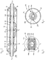
- FIG. 2 to 4 is an example of a concrete embodiment of the basic structure of such a transducer of the vibration type shown schematically in different sectional views.
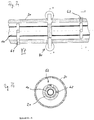
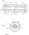
- the basic mechanical structure and its mode of action of the transducer shown by way of example with those of those in the US-A 2007/0119265 . US-A 2007/0119264 . US-B 66 91 583 , of the US-B 68 40 109 shown transducer comparable. Further embodiments and embodiments of the transducer according to the invention as well as details thereof are also in the FIGS. 6a, 6b . 7a, 7b . 8a, 8b and 9 are shown.
- the transducer serves to generate in a medium flowing through mechanical reaction forces, eg mass flow-dependent Coriolis forces, density-dependent inertial forces and / or viscosity-dependent frictional forces measurable, esp. Sensory detectable, act back on the transducer. Derived from these reaction forces , for example, a mass flow rate m, a density ⁇ and / or a viscosity ⁇ of the medium can be measured in the manner known to those skilled in the art.
- mechanical reaction forces eg mass flow-dependent Coriolis forces, density-dependent inertial forces and / or viscosity-dependent frictional forces measurable, esp. Sensory detectable
- the medium transducer For guiding the medium transducer comprises at least one - in the embodiment shown here, only substantially straight - measuring tube 10, which is vibrated during operation and thereby, oscillating about a static rest position, repeatedly elastically deformed, wherein the transducer at least a first has natural vibration mode in which at least the measuring tube can perform bending vibrations in an imaginary primary vibration level XZ.
- this imaginary primary vibration plane XZ also practically corresponds to the plane of the drawing Fig.
- the transducer In addition to the first natural vibration mode in the imaginary primary vibration plane XZ, the transducer also naturally has at least one second natural vibration mode in which at least the measuring tube can execute bending vibrations in an imaginary secondary vibration plane YZ substantially orthogonal to the imaginary primary vibration plane XZ.
- a counter-oscillator 20 is provided in the measuring transducer - substantially straight and substantially parallel to the measuring tube 10. This one is, as well as in Fig. 2 shown, with the formation of a - initially an inlet end of the measuring tube 10 defining - first coupling zone 11 # inlet side and the formation of a - virtually an outlet end of the measuring tube 10 defining - second coupling zone 12 # outlet side respectively fixed to the measuring tube 10.
- the counteroscillator 20 may be tubular or box-shaped and, for example, connected at the inlet end and at the outlet end with the measuring tube 10 that, as is quite common in such transducers, is substantially coaxially aligned with the measuring tube 10 and thus the measuring tube 10 from the counter-oscillator 20th at least partially encased.
- the counteroscillator 20 is designed much heavier than the measuring tube 10th
- the measuring tube 10 is connected to the inlet tube piece 11 via an inlet side in the region of the first coupling zone and via an outlet side in the region of the second coupling zone, in particular to the inlet tube piece 11 substantially identical to the medium. or laxative - not shown here - pipeline connected.
- Inlet pipe piece 11 and outlet pipe piece 12 are substantially straight in the illustrated embodiment and aligned with each other, the measuring tube 10 and an imaginary longitudinal axis L practically connecting the coupling zones.
- the measuring tube 10, inlet and outlet tube 11, 12 may be made in one piece, so that their manufacture can serve as a single tubular semi-finished.
- inlet tube piece 11 and outlet tube piece 12 are each formed by segments of a single, one-piece tube, these, if necessary, but also by means of individual, subsequently assembled, eg welded together, semifinished products are produced.
- the measuring tube is further formed so that it extends between the two coupling zones with substantially constant, esp. Kreisringförmigem, cross-section.
- the measuring tube 10 is formed substantially cylindrical.
- the measuring tube 10 is - as already mentioned several times - at least temporarily to lateral bending vibrations in the imaginary primary vibration level XZ, esp.
- Nutzmode at least proportionally, especially predominantly, audungt according to a natural first mode of natural vibration.
- the bending oscillations in the payload mode are aligned substantially transversely to an essentially coincident, in particular coincident, bending oscillation axis which is essentially coincident with the longitudinal axis L and connects the two coupling zones 11 #, 12 # to one another imaginarily.
- the measuring tube is excited during operation by means of the exciter arrangement at least temporarily so that it oscillates predominantly or exclusively in the imaginary primary vibration plane.
- the measuring tube 10th thereby excited with an oscillation frequency, f exc , which corresponds as closely as possible to a natural resonant frequency of the so-called f1 -Eigenmodes of the measuring tube 10, ie a symmetrical eigenmode in which, as in FIGS. 5b to 5d shown schematically, the vibrating, but not flowed through by the medium measuring tube 10 is bent substantially symmetrically with respect to a vertical axis to the longitudinal axis L substantially symmetrical and thereby essentially has a single antinode, see.
- f exc oscillation frequency
- measuring tube 10 and counteroscillator 20 thus oscillate in operation at least temporarily and / or proportionately laterally in a payload mode in which they jointly execute essentially coplanar bending oscillations in the imaginary primary oscillation plane XZ.
- the instantaneous expression of the deformation of the measuring tube 10 is, esp. In terms of their amplitudes, also dependent on the instantaneous mass flow m.
- the so-called Coriolismode as is customary in such transducers, for example, the natural mode of the anti-symmetric f2 -Eigenmodes, So serve those with two antinodes and / or the natural mode of the anti-symmetric f4 -Eigenmodes with four antinodes.
- measuring tube 10 and counter-oscillator 20 are further dimensioned so that the empty measuring tube 10 has a lowest natural natural frequency, f 10 , which is greater than or equal to a lowest natural natural frequency, f 20, of the counter-oscillator 20.
- measuring tube 10 and counter-oscillator 20 are dimensioned so that the filled with water measuring tube 10 has a lowest natural natural frequency, f 10, H2O , which is at least equal to a lowest natural natural frequency, f 20 , of the counter-oscillator 20.
- a further embodiment of the invention is also provided to tune measuring tube 10 and counter-oscillator 20 with respect to their vibration properties to each other so that a lowest natural natural frequency, f 10 , H2O measuring tube 10 even at least 1.1 times a lowest natural natural frequency, f 20 , the counter-oscillator 20 corresponds when it is completely filled with water.
- a natural resonant frequency, f 10, air of the f1 eigenmode of the empty measuring tube would approximately at 550 Hz
- a natural resonant frequency, f 10, H2O the f1 -Eigenmodes of the water-filled measuring tube would be about 450 Hz.
- the measuring tube 10 also leads, esp. Also based on the in the US-B 68 40 109 shown in operation, at least temporarily, esp.
- Torsional vibration axis, bending vibration axis as well as the longitudinal axis L may, as is quite common in such transducers, be substantially coincident.
- the transducer For generating mechanical oscillations of the measuring tube 10 - be it bending vibrations and / or torsional oscillations - the transducer further comprises a, in particular electrodynamic, exciter arrangement 40.
- This serves to inform a correspondingly conditioned electrical drive signal by means of the operating and evaluation electronics, For example, with a regulated current and / or a regulated voltage, fed electrical excitation energy E exc in a on the measuring tube 10, for example, pulsed, clocked or harmonious, acting and this convert elastically deforming exciter force F exc in the manner described above.
- the excitation force F exc can here, as in Fig.
- the excitation order as well with such transducers quite common, also designed and arranged in the transducer that it acts substantially centrally of the measuring tube and / or at least selectively fixed along an imaginary central peripheral line of the measuring tube outside of this.
- electrodynamic plunger coil assembly with a fixed to the counteroscillator 20 cylindrical excitation coil, which is traversed in operation by a corresponding excitation current, and with a at least partially immersed in the exciter coil permanent magnet armature, the insb. centered, is fixed to the measuring tube 10 serve.
- the exciter assembly 40 may be e.g. also be realized as an electromagnet or as a seismic exciter.
- a sensor arrangement which is customary for such measuring transducers can be used, in which, in the manner known to the person skilled in the art, by means of an inlet-side, from the first coupling zone 11 # spaced on the measuring tube 10 placed first vibration sensor 50A and by means of an outlet side, spaced from the second coupling zone 12 # placed on the measuring tube 10, esp.
- second vibration sensor 50B detects the movements of the measuring tube 10 and be converted into a corresponding first or second sensor signal S 1 , S 2 .
- sensors 50A, 50B for example, the oscillations relative to the counteroscillator, for example differential measuring, electrodynamic velocity sensors or else electrodynamic displacement sensors or acceleration sensors can be used.
- electrodynamic sensor arrangements or in addition to the same can also be used by means of resistive or piezoelectric strain gauges measuring or opto-electronic sensors for detecting the vibrations of the measuring tube 10.
- the exciter assembly 40 such as in Fig. 2 or Fig. 3 shown schematically, so formed and arranged in the transducer so that it simultaneously, esp. Differentially, on measuring tube 10 and counter-oscillator 20 acts.
- the exciter arrangement 40 for this purpose has at least one first excitation coil 41a, which is at least temporarily energized by the excitation current or an excitation subcurrent, fixed to a lever 41c connected to the measuring tube 10 and via this and an armature fixed externally to the counteroscillator 20 41b differentially on the measuring tube 10 and the counteroscillator 20 acts.
- This arrangement also has the advantage that, on the one hand, the counter-oscillator 20 and thus also the transducer housing 100 are kept small in cross-section and nevertheless the exciter coil 41a, esp. Also during assembly, is easily accessible.
- this embodiment of the exciter assembly 40 is that any used, esp.
- bobbin 41d are also fixed to the counteroscillator 20 and thus virtually no influence have the resonance frequencies of the measuring tube 10.
- the exciter coil 41a can also be supported by the counteroscillator 20 and, accordingly, the armature 41b of the measuring tube 10.
- the sensor arrangement 50 can also be designed and arranged in the transducer such that the vibrations of the measuring tube 10 and counteroscillator 20 are detected differentially by it.
- the sensor arrangement 50 comprises a sensor coil 51a fixed to the measuring tube 10.
- the sensor coil 51a is arranged as close as possible to an armature 51b fixed to the counteroscillator 20 and magnetically coupled therewith in such a way that a variable measuring voltage is induced in the sensor coil, the lateral relative movements between the measuring tube 10 and counteroscillator 20 changing by a relative distance between sensor coil and armature and / or a relative position of the sensor coil with respect to the armature changing rotational relative movements between the measuring tube 10 and counter-oscillator 20 is influenced.
- the sensor coil 51a can also be fixed to the counter-oscillator 20 and, in a corresponding manner, the armature 51b coupled to it on the measuring tube 10.
- vibration exciters and vibration sensors according to the same principle of action, esp. Essentially form each other structurally. Furthermore, it is also possible to fix coil and / or armature of excitation and / or sensor arrangement waiving a mediating lever each directly on the measuring tube or the counteroscillator.
- measuring tube 10, counteroscillator 20 and the attached sensor and exciter assemblies 40, 50 are further coordinated with respect to their mass distribution, that the thus formed, by means of the input and the outlet tube piece 11, 12 suspended inner part of the transducer one Mass center MS has, at least within the measuring tube 10, but preferably as close as possible to the Meßrohrlteilsachse L.
- the inner part is further designed such that it has a first inertial main axis T 1 aligned with the inlet pipe piece 11 and the outlet pipe piece 12 and lying at least partially within the measuring pipe 10.
- the inner part of the transducer is designed according to a further embodiment of the invention such that a first inertial main axis T 1 thereof coincides with the upper longitudinal axis L substantially. Further, according to a further embodiment of the invention, the inner part of the transducer is designed such that a second inertial main axis T 2 thereof substantially coincides with the above-mentioned central axis.
- leads are provided, which are performed at least partially within the converter housing.
- the leads may be at least proportionally formed as electrical, at least partially wrapped in an electrical insulation wires, eg inform of "twisted pair" cables, ribbon cables and / or coaxial cables.
- the connection lines can also be formed, at least in sections, by means of conductor tracks of a, in particular flexible, optionally painted circuit board.
- the transducer according to the invention as well as from the synopsis of FIGS. 2 and 5a to 5d can be seen, to further improve the accuracy and based on the in the above-mentioned US-A 2007/0186685 .
- US-B 66 91 583 , or US-B 68 40 109 proposed transducer further comprises in the region of the first coupling zone with the inlet pipe piece 11 and the measuring tube 10 coupled first boom 15, the-as in Fig.
- the mode of action of the inner part thus formed corresponds to that in the mentioned US-A 2007/0186685 .
- US-A 2007/0119265 US-A 2007/0119264 .
- US-B 66 91 583 or US-B 68 40 109 shown Interior parts.
- each of the two arms 15, 16 may be formed, for example, substantially tubular or sleeve-shaped, so that it is practically pushed by means of a pushed onto the counteroscillator 20, esp. Metallic, sleeve can be formed, in particular, even if the counteroscillator 20 has already been connected to the measuring tube 10.
- each of the sleeves 15, 16 forming sleeves has at least one annular groove, cf. also for that mentioned US-A 2007/0186685 . US-A 2007/0119264 or US-A 2007/0119265 ,
- any of the materials customary for such transducers such as e.g. Steel, titanium, tantalum, zirconium, etc., or appropriate combinations of these materials can be used.
- the use of titanium for the measuring tube 10 and the inlet tube 11 and the outlet tube 12 has been found to be particularly suitable, for example, for reasons of cost savings, both for the counteroscillator 20 and the optionally provided boom 15, 16 and for the converter housing 30 the use of steel is quite beneficial.
- transducer not only natural vibration modes both in the imaginary primary vibration level XZ and in the orthogonal notional secondary vibration plane YZ but also that at least some of the vibration modes in the secondary vibration plane YZ may have such a natural resonant frequency, which may be substantially equal to a natural resonant frequency of a corresponding vibration mode in the primary vibration level XZ.
- Such mutually corresponding oscillation modes can also each have waveforms of the same order, ie in each case the same number of nodes.
- a first spring element 61 and a second spring element 62 are also provided in the transducer according to the invention.
- Each of the at least two, for example, substantially identical design, spring elements is - as well as in the Fig. 6a to 8b schematically illustrated - fixed with a respective measuring tube-side first end on the measuring tube 10 and with a respective counter-oscillating second end on the counter-oscillator 20, for example, in each case at the same distance from the center of the measuring tube.
- the spring elements are arranged in the transducer such that each of the two spring elements 61, 62 is anchored both from each of the two coupling zones 11 #, 12 # and from the excitation arrangement 40 at a distance with measuring tube and counteroscillator and insofar from the two coupling zones 11 #. , 12 # and spaced from the exciter assembly 40 acts on measuring tube and counter-oscillator.
- the first spring element 61 is at a distance from the second spring element 62 fixed to measuring tube and counteroscillator, so that so both the measuring tube ends and the counteroscillator ends of the two spring elements 61, 62 are each spaced apart.
- the spring elements 61, 62 each with the measuring tube side first end to form a respective substantially rigid and / or substantially backlash-free storage on the measuring tube and the counteroscillator side second end to form a respective substantially rigid and / or im essential play-free storage to fix the counter-oscillator.
- the first spring element in a lying between the first coupling zone 11 # and the at least one vibration exciter inlet side region fixed to measuring tube and counter-oscillator.
- This refinement is further provided to fix the second spring element in a lying between the second coupling zone 12 # and the at least one vibration exciter outlet side region of measuring tube and counteroscillator.
- the spring element 61, 62 as well as from the synopsis of Fig. 7a and 7b it can be seen so arranged in the transducer that the first spring element 61 along a parallel to the longitudinal axis L extending imaginary lateral line of the measuring tube 10 fixed to selbigem, which also parallel to this imaginary side line of the measuring tube 10, along which the second spring element 62 with its meßrohr facilityen end fixed to the measuring tube is substantially diametrically opposite.
- the two spring elements 61, 62 also point symmetrical with respect to a center of gravity of the measuring tube 10 or the mentioned center of mass MS of the transducer are arranged in selbigen.
- the measuring tube-side ends of the two spring elements 61, 62 should advantageously lie on a common imaginary diagonal of the transducer passing through the center of gravity; Similarly, then the counter-oscillator ends of the two spring elements 61, 62 are on a common further, also passing through the center of gravity imaginary diagonal of the transducer.
- This arrangement of the spring elements has the advantage that not only very effective frequency shifts between resonant frequencies of corresponding vibration modes in the primary and secondary vibration level can be achieved, but also also in a very simple way an additional frequency shift between the resonant frequencies of the aforementioned torsional vibrations of the measuring tube and those of Lateral vibrations, esp. Those in the primary vibration level, can be realized without thereby significantly hindering the excitation of the torsional vibrations as such.
- the at least two spring element 61, 62 are formed and arranged in the transducer, that by means of the two spring elements a lowest natural frequency of the above-mentioned first natural vibration mode is set smaller in the imaginary primary vibration level, as a lowest natural frequency of the second natural Vibration mode in the imaginary secondary vibration plane.
- the transducer form so that a frequency difference between the lowest natural frequency of the first natural vibration mode and the lowest natural frequency of the second natural vibration mode greater than 50 Hz, esp. Greater than 100 Hz, is set.
- each of the two spring elements 61, 62 has a spring rigidity, of which one bending vibration of the measuring tube in the primary vibration plane XZ inhibiting primary component is different from a bending vibration of the measuring tube in the secondary Vibration level YZ inhibiting secondary component.
- each of the two spring elements 61, 62 is formed and arranged in the transducer so that the primary component of the spring stiffness is smaller in each case than the associated secondary component.
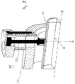
- the aforementioned difference between primary and associated secondary component can be achieved for the respective spring element, for example, in a simple manner that - as for example from the synopsis of FIGS. 6a and b apparent or as in Fig. 9 exemplified by the first spring element 61 - each of the spring elements each as an elongated body, such as a rod, a coil spring, a leaf spring or the like, formed and arranged in each case in the transducer that it is in operation due to Bending vibrations of the measuring tube 10 in the primary plane of vibration to a both respective spring element ends imaginarily connecting longitudinal axis is bent transversely in the manner of a clamped at both ends string.
- each of the, in particular identical, spring elements are each formed by means of a, esp. Metallic, rod.
- a metallic rod as a spring element has, apart from a comparatively simple, nevertheless very robust construction of the spring elements, at the same time very good spring action, in particular the advantage that in the production of standardized, in this respect also cost-effective mass-produced readily be used can.
- each of the elongated body designed, esp. Rod-shaped or rod-shaped, spring elements extends substantially in the radial direction of the measuring tube and / or counter-oscillator.
- the two spring elements are placed in the transducer so that each of the two spring elements is arranged in an imaginary extending through the inlet-side region and the outlet region straight cutting plane of the measuring tube.
- each of the two, for example, rod-shaped or rod-shaped, spring elements is mounted proportionately at imaginary points of intersection of the measuring tube with the imaginary secondary vibration level YZ. It is further provided that each of the two spring elements is mounted proportionately at imaginary points of intersection of the counter-oscillator with the secondary vibration plane YZ.
- both are preferably so arranged in the transducer that they are effectively within the secondary vibration plane YZ.
- the spring elements are further arranged in the transducer, that the first spring element is fixed at least in the vicinity of an inlet-side peripheral line of the measuring tube to the latter along which said first vibration sensor here on the inlet side - effectively detected movements of the measuring tube, and that second spring element is fixed to the latter at least in the vicinity of an outlet-side peripheral line of the measuring tube, along which the mentioned second vibration sensor - here outlet side - detected movements of the measuring tube effectively.
- the spring element are further arranged in the transducer so that the first spring element and the aforementioned first vibration sensor are each proportionately fixed along at least the extent of the common inlet side circumference of the measuring tube to the latter, and that the second spring element and the aforementioned second vibration sensor each proportionately along at least the extent far common outlet-side circumference of the measuring tube are fixed to this.
- the spring elements are fixed along a in the primary vibration plane biegeschwingendem measuring tube substantially non-distorting neutral fiber of the measuring tube to selbigem.
- the counteroscillator executes during operation at least temporarily bending vibrations about the bending vibration axis
- the spring elements are fixed along a in bending-bending counter-oscillator substantially non-distorting neutral fiber of the counter-oscillator to selbigem.
- the attachment of the spring elements along the neutral fibers of measuring tube and counter-oscillator can be achieved, for example, that the torsional vibrations of the measuring tube to the torsional vibration axis substantially coincident with the bending vibration axis effectively inhibiting spring stiffness of the spring elements is minimized and thus only a small effect on the behavior of the Measuring transducer in torsionsschwingendem measuring tube has.
- the transducer comprises, as well as in the Fig. 8a schematically, further an additional third spring element 63 and a fourth spring element 64.
- The, for example, in turn, substantially identical, spring elements are again arranged in the transducer so that each of the four now Spring elements 61, 62, 63, 64 - as well as from the synopsis of Fig. 2 and Fig. 8a can be seen-each of the coupling zones 11 #, 12 # as well as the exciter assembly 40 spaced from the measuring tube 10 and counter-oscillator 20 is fixed.
- the spring elements 61, 62, 63, 64 are further arranged in the transducer so that each of the four spring elements is also each spaced from each of the respective other three spring elements.
- the spring elements are arranged so that - as from the synopsis of Fig. 8a and 8b readily apparent - pairs spring elements together, here so the first and third spring element 61, 63 on the one hand and the second and fourth spring element 62, 64 on the other hand, in each case substantially diametrically opposed.
- the transducer according to the invention is characterized by a variety of settings that allow the expert in the knowledge of the present invention, a separation of resonant frequencies of selected modes of vibration of the measuring tube in the primary and secondary vibration level to achieve a high quality, esp. Even after a specification of external or internal mounting dimensions of the transducer.
- the parameters to be set for the actual implementation in detail for the required stiffness of the spring elements as well as their respective optimal positioning in the transducer can be adapted accordingly to the nominal diameter DN actually provided for the measuring tube 10 as well as the insertion length provided for the measuring tube ,
- the transducer according to the invention is both for measuring tubes with rather smaller nominal sizes DN in the range of less than 40 mm and in particular for use in piping with a caliber of more than 50 mm and, consequently, for measuring tubes with nominal widths of substantially greater than 40 mm well suited.
Landscapes
- Physics & Mathematics (AREA)
- Fluid Mechanics (AREA)
- General Physics & Mathematics (AREA)
- Measuring Volume Flow (AREA)
Claims (15)
- Transducteur du type à vibrations pour un produit s'écoulant dans une conduite, lequel transducteur comprend :- un tube de mesure (10) vibrant au moins temporairement, communiquant avec la conduite par l'intermédiaire d'un élément de tube d'entrée (11) débouchant côté entrée et par l'intermédiaire d'un élément de tube de sortie (12) débouchant côté sortie, lequel tube de mesure est destiné à guider le produit à mesurer ;- un contre-vibrateur (20) qui, en formant une première zone de couplage (11#), est fixé côté entrée sur le tube de mesure (10) et, en formant une deuxième zone de couplage (12#), est fixé côté sortie sur le tube de mesure (10) ;- un circuit d'excitation (40) fixé à l'extérieur du tube de mesure (10), notamment pour l'essentiel de façon centrée et/ou au moins ponctuellement le long d'une ligne périphérique du tube de mesure (10), centrale et imaginaire, lequel circuit d'excitation (40) est destiné à exciter en vibrations au moins le tube de mesure (10), lequel circuit d'excitation (40) comprend au moins un excitateur de vibrations, notamment unique et/ou constitué d'une bobine ;- un circuit capteur (50) destiné à la détection des vibrations au moins du tube de mesure (10), lequel circuit capteur comprend, côté entrée, un premier capteur de vibrations, conçu au moyen d'une bobine, ainsi que, côté sortie, un deuxième capteur de vibrations, conçu au moyen d'une bobine ;- un premier élément élastique (61) et un deuxième élément élastique (62, 63, 64), chacun des au moins deux éléments élastiques (61, 62, 63, 64) étant fixé sur le tube de mesure (10) et le contre-vibrateur (20), à distance à la fois de chacune des deux zones de couplage (11#, 12#) et du circuit d'excitation (40), de telle sorte que le premier élément élastique est fixé sur le tube de mesure et sur le contre-vibrateur, dans une zone côté entrée située entre la première zone de couplage (11#) et l'au moins un excitateur de vibrations : ainsi que- un boîtier de transducteur (30) ;- le transducteur présentant au moins un premier mode de vibration naturel, dans lequel le tube de mesure peut exécuter des vibrations de flexion dans un plan de vibration primaire imaginaire (XZ), et au moins un deuxième mode de vibration naturel, dans lequel le tube de mesure peut exécuter des vibrations de flexion dans un plan de vibration primaire imaginaire (XZ) pour l'essentiel orthogonal au plan de vibration secondaire (YZ), et le tube de mesure exécutant, en fonctionnement, au moins temporairement et/ou au moins partiellement des vibrations de flexion autour d'un axe de vibration de flexion imaginaire, qui relie entre elles les deux zones de couplage (11#, 12#), et- une fréquence propre minimale du premier mode de vibration naturel étant réglée, au moyen des deux éléments élastiques, à une valeur inférieure à la fréquence propre minimale du deuxième mode de vibration naturel, notamment de telle sorte qu'un écartement entre la fréquence propre minimale du premier mode de vibration naturel et la fréquence propre minimale du deuxième mode de vibration naturel est réglé à une valeur supérieure à 50 Hz ; et/ou chacun des deux éléments élastiques présentant une rigidité élastique, éléments par rapport auxquels une composante primaire inhibant les vibrations de flexion du tube de mesure dans le plan de vibration primaire (XZ) est différente d'une composante secondaire inhibant les vibrations de flexion du tube de mesure dans le plan de vibration secondaire (YZ), notamment de telle sorte que chacun des deux éléments élastiques est conçu et disposé dans le transducteur de telle manière que la composante primaire de sa rigidité élastique est respectivement inférieure à la composante secondaire correspondante.
- Transducteur selon l'une des revendications précédentes, pour lequel le tube de mesure est excité, en fonctionnement, au moyen du circuit d'excitation, au moins partiellement de telle sorte qu'il oscille au moins partiellement, notamment essentiellement ou exclusivement, dans le plan de vibration primaire imaginaire.
- Transducteur selon la revendication précédente, pour lequel le circuit d'excitation (40) est alimenté, en fonctionnement, au moins partiellement par un signal d'attaque électrique.
- Transducteur selon l'une des revendications précédentes, pour lequel le premier élément élastique est fixé sur le tube de mesure et le contre-vibrateur de façon espacée par rapport au deuxième élément élastique.
- Transducteur selon la revendication précédente, pour lequel le deuxième élément élastique est fixé sur le tube de mesure et le contre-vibrateur, dans une zone côté sortie située entre la zone de couplage (12#) et l'au moins un excitateur de vibrations, notamment de telle sorte que les deux éléments élastiques sont disposés, dans le transducteur, dans un plan de coupe droit du tube de mesure, s'étendant de façon imaginaire à travers la zone côté entrée et la zone côté sortie.
- Transducteur selon l'une des revendications précédentes, pour lequel le circuit d'excitation comprend au moins une bobine.
- Transducteur selon la revendication précédente, pour lequel l'au moins une bobine du circuit d'excitation est reliée mécaniquement avec le contre-vibrateur, notamment couplée de façon rigide.
- Transducteur selon la revendication précédente, pour lequel un premier élément élastique et le premier capteur de vibrations sont chacun fixés partiellement le long d'au moins une ligne périphérique commune, côté entrée, du tube de mesure, et pour lequel le deuxième élément élastique et le deuxième capteur de vibrations sont chacun fixés partiellement le long d'au moins une ligne périphérique commune, côté sortie, du tube de mesure.
- Transducteur selon l'une des revendications précédentes,- pour lequel le tube de mesure (10) et le contre-vibrateur (20) sont alignés l'un par à l'autre essentiellement de manière coaxiale : et/ou- pour lequel le tube de mesure (10) est entouré au moins partiellement par le contre-vibrateur (20) ; et/ou- pour lequel le contre-vibrateur (20) est pour l'essentiel de forme tubulaire ; et/ou- pour lequel le contre-vibrateur (20) est pour l'essentiel droit ; et/ou- pour lequel le tube de mesure (10) s'étend avec pour l'essentiel une section constante, notamment de forme annulaire, entre les deux zones de couplage (11#, 12#) ; et/ou- pour lequel le tube de mesure (10) est pour l'essentiel de forme cylindrique ; et/ou- pour lequel le tube de mesure (10) communique avec la conduite par l'intermédiaire d'un élément de tube d'entrée (11) débouchant côté entrée et par l'intermédiaire d'un élément de tube de sortie (12) débouchant côté sortie, et pour lequel le boîtier de transducteur (30) est fixé sur l'élément de tube d'entrée (11) et sur l'élément de tube de sortie (12).
- Transducteur selon l'une des revendications précédentes, pour lequel le tube de mesure (10) est pour l'essentiel droit.
- Transducteur selon la revendication précédente- pour lequel le contre-vibrateur exécute également, en fonctionnement, au moins temporairement des vibrations de flexion autour de l'axe de vibration de flexion, et les éléments élastiques sont fixés, lorsque le contre-vibrateur exécute des vibrations de flexion, sur le contre-vibrateur le long d'une fibre neutre, pour l'essentiel sans effet distorsif, du contre-vibrateur ; et/ou- pour lequel le tube de mesure exécute, en fonctionnement, au moins partiellement des vibrations de torsion autour d'une axe de vibration de torsion pour l'essentiel parallèle, notamment coïncidant, avec l'axe de vibration de flexion.
- Transducteur selon l'une des revendications précédentes,- pour lequel les éléments élastiques sont chacun fixés sur le tube de mesure avec une première extrémité côté tube de mesure, notamment en formant respectivement une structure rigide et/ou sans jeu, et sur le contre-vibrateur avec une deuxième extrémité côté contre-vibrateur, notamment en formant respectivement une structure rigide et/ou sans jeu ; et/ou- pour lequel chacun des deux éléments élastiques, notamment de conception identique, est formé au moyen d'une tige disposée dans le transducteur, notamment métallique et/ou s'étendant pour l'essentiel en direction axiale par rapport au tube de mesure et/ou au contre-vibrateur : et/ou- pour lequel les deux éléments élastiques sont disposés dans le transducteur selon une symétrie ponctuelle par rapport à un centre de gravité du tube de mesure ; et/ou- pour lequel chacun des deux éléments élastiques est logé partiellement en des points d'intersection imaginaires du tube de mesure avec le plan de vibration secondaire (YZ), notamment de telle sorte que chacun des deux éléments élastiques sont logés partiellement également en des points d'intersection imaginaires du contre-vibrateur avec le plan de vibration secondaire (YZ).
- Transducteur selon l'une des revendications précédentes, comprenant en outre un troisième élément élastique et un quatrième élément élastique, chacun des quatre éléments élastiques étant fixé sur le tube de mesure et le contre-vibrateur de façon espacée par rapport aux zones de couplage (11#, 12#) et au circuit d'excitation (40).
- Transducteur selon la revendication précédente, pour lequel chacun des quatre éléments élastiques, notamment de conception identique, est respectivement espacé par rapport à chacun des trois autres éléments élastiques, notamment de telle sorte que les éléments élastiques (61, 63) correspondant par paires côté entrée sont placés respectivement pour l'essentiel de manière diamétralement opposée sur le tube de mesure (10) et les éléments élastiques (62, 64) correspondant par paires côté sortie sont placés respectivement pour l'essentiel de manière diamétralement opposée sur le tube de mesure (10).
- Utilisation d'un transducteur selon l'une des revendications précédentes dans un appareil de mesure en ligne destiné à la mesure et/ou la surveillance d'au moins un paramètre, notamment un débit massique, m, une densité, ρ, et/ou une viscosité, η, d'un produit s'écoulant dans une conduite, notamment un débitmètre Coriolis, un densimètre ou un viscosimètre.
Applications Claiming Priority (2)
| Application Number | Priority Date | Filing Date | Title |
|---|---|---|---|
| DE102007050686A DE102007050686A1 (de) | 2007-10-22 | 2007-10-22 | Meßwandler vom Vibrationstyp |
| PCT/EP2008/064170 WO2009053344A1 (fr) | 2007-10-22 | 2008-10-21 | Transducteur de type à vibration |
Publications (2)
| Publication Number | Publication Date |
|---|---|
| EP2201337A1 EP2201337A1 (fr) | 2010-06-30 |
| EP2201337B1 true EP2201337B1 (fr) | 2018-09-12 |
Family
ID=40210418
Family Applications (1)
| Application Number | Title | Priority Date | Filing Date |
|---|---|---|---|
| EP08841933.8A Not-in-force EP2201337B1 (fr) | 2007-10-22 | 2008-10-21 | Transducteur de vibrations |
Country Status (4)
| Country | Link |
|---|---|
| US (1) | US7658115B2 (fr) |
| EP (1) | EP2201337B1 (fr) |
| DE (1) | DE102007050686A1 (fr) |
| WO (1) | WO2009053344A1 (fr) |
Families Citing this family (7)
| Publication number | Priority date | Publication date | Assignee | Title |
|---|---|---|---|---|
| DE102013101369B4 (de) * | 2013-02-12 | 2021-02-18 | Endress + Hauser Flowtec Ag | Coriolis-Massendurchfluß-Meßgerät |
| DE102007062397A1 (de) | 2007-12-20 | 2009-06-25 | Endress + Hauser Flowtec Ag | Meßwandler vom Vibrationstyp |
| US20150153210A1 (en) * | 2013-12-04 | 2015-06-04 | Gilbarco Inc. | Fuel dispenser coriolis flow meter |
| DE102016112002B4 (de) * | 2016-06-30 | 2023-03-23 | Endress + Hauser Flowtec Ag | Verfahren zum Bestimmen eines physikalischen Parameters eines kompressiblen Mediums mit einem Messaufnehmer vom Vibrationstyp und Messaufnehmer zur Durchführung eines solchen Verfahrens |
| DE102016007905A1 (de) * | 2016-06-30 | 2018-01-04 | Endress+Hauser Flowtec Ag | Verfahren zum Betreiben eines Messaufnehmers vom Vibrationstyp |
| DE102018119330B3 (de) * | 2018-08-08 | 2019-12-05 | Endress+Hauser Flowtec Ag | Spulenvorrichtung eines Schwingungssensors oder Schwingungserregers und Messaufnehmer bzw. Messgerät |
| DE102023112374A1 (de) * | 2023-05-10 | 2024-11-14 | Endress+Hauser Flowtec Ag | Meßsystem |
Family Cites Families (35)
| Publication number | Priority date | Publication date | Assignee | Title |
|---|---|---|---|---|
| US3329019A (en) * | 1964-10-26 | 1967-07-04 | Anatole J Sipin | Mass flow metering means |
| US4491025A (en) * | 1982-11-03 | 1985-01-01 | Micro Motion, Inc. | Parallel path Coriolis mass flow rate meter |
| US4823614A (en) | 1986-04-28 | 1989-04-25 | Dahlin Erik B | Coriolis-type mass flowmeter |
| FR2598801A1 (fr) * | 1986-05-13 | 1987-11-20 | Assistance Indle Dauphinoise A | Debitmetre massique a elasticite multimodale |
| GB2212613B (en) | 1987-11-19 | 1991-07-03 | Schlumberger Ind Ltd | Improvements in single vibrating tube transducers |
| DE4124295A1 (de) | 1991-07-22 | 1993-01-28 | Krohne Ag | Massendurchflussmessgeraet |
| EP0547455B1 (fr) | 1991-12-19 | 1996-09-18 | Krohne AG | Débitmètre de masse |
| DE4224379C2 (de) | 1992-07-06 | 1998-05-20 | Krohne Messtechnik Kg | Massendurchflußmeßgerät |
| JP2758798B2 (ja) | 1992-11-19 | 1998-05-28 | 株式会社オーバル | コリオリ流量計 |
| DK0685712T3 (da) | 1994-05-26 | 2000-10-02 | Flowtec Ag | Massegennemstrømningsdetektor ifølge Coriolis-princippet |
| US5691485A (en) | 1994-06-06 | 1997-11-25 | Oval Corporation | Coaxial double tube type Coriolis flowmeter |
| JPH08247816A (ja) | 1995-03-09 | 1996-09-27 | Fuji Electric Co Ltd | 質量流量計 |
| ES2149943T3 (es) | 1995-07-21 | 2000-11-16 | Flowtec Ag | Medidor de caudal masico segun el principio de coriolis con al menos un tubo de medicion. |
| EP0759542B1 (fr) * | 1995-08-21 | 2004-11-10 | Oval Corporation | Débitmètre à effet Coriolis |
| US5945609A (en) | 1996-03-08 | 1999-08-31 | Fuji Electric Co., Ltd. | Mass flowmeter for measuring flow rate of a fluid |
| US5796012A (en) | 1996-09-19 | 1998-08-18 | Oval Corporation | Error correcting Coriolis flowmeter |
| JP2898266B1 (ja) * | 1998-01-23 | 1999-05-31 | 株式会社オーバル | 二重直管式コリオリ流量計 |
| US5979246A (en) | 1998-02-09 | 1999-11-09 | Micro Motion, Inc. | Spring rate balancing of the flow tube and a balance bar in a straight tube Coriolis flowmeter |
| DE19840782C2 (de) | 1998-09-08 | 2001-09-06 | Krohne Messtechnik Kg | Massendurchflußmeßgerät |
| DE19908072C2 (de) | 1999-02-12 | 2002-10-17 | Krohne Ag Basel | Massendurchflußmeßgerät |
| JP3224788B2 (ja) | 1999-03-02 | 2001-11-05 | 株式会社オーバル | 直管シングルチューブコリオリ流量計 |
| US6327915B1 (en) | 1999-06-30 | 2001-12-11 | Micro Motion, Inc. | Straight tube Coriolis flowmeter |
| US6487917B1 (en) * | 2000-05-02 | 2002-12-03 | Micro Motion, Inc. | Low thermal stress balance bar for a coriolis flowmeter |
| JP5044801B2 (ja) * | 2000-12-21 | 2012-10-10 | ダイキン工業株式会社 | 含フッ素重合体の改質法およびその制御方法 |
| US6691583B2 (en) | 2001-04-24 | 2004-02-17 | Endress + Hauser Flowtec Ag | Vibratory transducer |
| WO2003095949A1 (fr) | 2002-05-08 | 2003-11-20 | Endress + Hauser Flowtec Ag | Amortisseur d'oscillations de torsion pour transformateur de mesure de type vibrant |
| US7424376B2 (en) * | 2002-07-25 | 2008-09-09 | Carpenter Brent L | Precise pressure measurement by vibrating an oval conduit along different cross-sectional axes |
| DE10351311B3 (de) * | 2003-10-31 | 2005-06-30 | Abb Patent Gmbh | Coriolis-Massendurchflussmessgerät |
| US7077014B2 (en) | 2004-06-23 | 2006-07-18 | Endress + Hauser Flowtec Ag | Vibration-type measuring transducer |
| DE102004030392A1 (de) * | 2004-06-23 | 2006-01-19 | Endress + Hauser Flowtec Ag, Reinach | Meßwandler vom Vibrationstyp |
| JP4668664B2 (ja) * | 2005-04-08 | 2011-04-13 | 株式会社オーバル | 多重管構造形直管式コリオリ流量計 |
| US7475603B2 (en) | 2005-11-15 | 2009-01-13 | Endress + Hauser Flowtec Ag | Measurement transducer of vibration-type |
| US7490521B2 (en) | 2005-11-15 | 2009-02-17 | Endress + Hauser Flowtec Ag | Measurement transducer of vibration type |
| US7472607B2 (en) | 2005-11-15 | 2009-01-06 | Endress + Hauser Flowtec Ag | Measurement transducer of vibration type |
| MX2008013262A (es) * | 2006-05-01 | 2008-10-28 | Micro Motion Inc | Una estructura equilibradora para un medidor de flujo de coriolis de tubo curvo unico. |
-
2007
- 2007-10-22 DE DE102007050686A patent/DE102007050686A1/de not_active Withdrawn
-
2008
- 2008-10-21 EP EP08841933.8A patent/EP2201337B1/fr not_active Not-in-force
- 2008-10-21 WO PCT/EP2008/064170 patent/WO2009053344A1/fr not_active Ceased
- 2008-10-22 US US12/289,169 patent/US7658115B2/en active Active
Non-Patent Citations (1)
| Title |
|---|
| None * |
Also Published As
| Publication number | Publication date |
|---|---|
| WO2009053344A1 (fr) | 2009-04-30 |
| US20090145244A1 (en) | 2009-06-11 |
| DE102007050686A1 (de) | 2009-04-23 |
| US7658115B2 (en) | 2010-02-09 |
| EP2201337A1 (fr) | 2010-06-30 |
Similar Documents
| Publication | Publication Date | Title |
|---|---|---|
| EP2223057B1 (fr) | Convertisseur de mesure du type à vibrations | |
| EP2122311B1 (fr) | Transducteur de mesure du type à vibrations | |
| EP2705334B1 (fr) | Capteur de mesure de type vibratoire et système de mesure formé avec ce capteur de mesure | |
| EP1502084B1 (fr) | Amortisseur d'oscillations de torsion pour transformateur de mesure de type vibrant | |
| EP2502032B1 (fr) | Système de mesure muni d'un ensemble de tubes présentant deux tubes de mesure parcourus en parallèle par un milieu et procédé de surveillance dudit ensemble du tubes | |
| EP1381830B1 (fr) | Transducteur de mesure de type vibratoire | |
| EP2201337B1 (fr) | Transducteur de vibrations | |
| EP2304393B1 (fr) | Transducteur de mesure du type à vibration | |
| WO2011085851A1 (fr) | Capteur de mesure du type à vibrations | |
| EP2406591A1 (fr) | Capteur de mesure à vibration et instrument de mesure en ligne muni d'un tel capteur de mesure | |
| EP1759178B1 (fr) | Transducteur du type transducteur de vibrations | |
| EP1345013A1 (fr) | Débitmètre massique de Coriolis utilisant un mélangeur à tourbillon | |
| EP2694929B1 (fr) | Procédé de réglage fin d'un tube | |
| DE102009055069A1 (de) | Meßaufnehmer vom Vibrationstyp | |
| DE10235322A1 (de) | Meßwandler vom Vibrationstyp | |
| EP1949048B1 (fr) | Convertisseur de mesure du type a vibrations | |
| DE102006062185A1 (de) | Meßwandler vom Vibrationstyp | |
| DE102006062220A1 (de) | Meßwandler vom Vibrationstyp | |
| DE102006062219A1 (de) | Meßwandler vom Vibrationstyp |
Legal Events
| Date | Code | Title | Description |
|---|---|---|---|
| PUAI | Public reference made under article 153(3) epc to a published international application that has entered the european phase |
Free format text: ORIGINAL CODE: 0009012 |
|
| 17P | Request for examination filed |
Effective date: 20100408 |
|
| AK | Designated contracting states |
Kind code of ref document: A1 Designated state(s): AT BE BG CH CY CZ DE DK EE ES FI FR GB GR HR HU IE IS IT LI LT LU LV MC MT NL NO PL PT RO SE SI SK TR |
|
| AX | Request for extension of the european patent |
Extension state: AL BA MK RS |
|
| DAX | Request for extension of the european patent (deleted) | ||
| GRAP | Despatch of communication of intention to grant a patent |
Free format text: ORIGINAL CODE: EPIDOSNIGR1 |
|
| INTG | Intention to grant announced |
Effective date: 20180515 |
|
| GRAS | Grant fee paid |
Free format text: ORIGINAL CODE: EPIDOSNIGR3 |
|
| GRAA | (expected) grant |
Free format text: ORIGINAL CODE: 0009210 |
|
| AK | Designated contracting states |
Kind code of ref document: B1 Designated state(s): AT BE BG CH CY CZ DE DK EE ES FI FR GB GR HR HU IE IS IT LI LT LU LV MC MT NL NO PL PT RO SE SI SK TR |
|
| REG | Reference to a national code |
Ref country code: GB Ref legal event code: FG4D Free format text: NOT ENGLISH |
|
| REG | Reference to a national code |
Ref country code: CH Ref legal event code: EP |
|
| REG | Reference to a national code |
Ref country code: IE Ref legal event code: FG4D Free format text: LANGUAGE OF EP DOCUMENT: GERMAN |
|
| REG | Reference to a national code |
Ref country code: DE Ref legal event code: R096 Ref document number: 502008016340 Country of ref document: DE |
|
| REG | Reference to a national code |
Ref country code: AT Ref legal event code: REF Ref document number: 1041164 Country of ref document: AT Kind code of ref document: T Effective date: 20181015 |
|
| REG | Reference to a national code |
Ref country code: FR Ref legal event code: PLFP Year of fee payment: 11 |
|
| REG | Reference to a national code |
Ref country code: NL Ref legal event code: MP Effective date: 20180912 |
|
| REG | Reference to a national code |
Ref country code: LT Ref legal event code: MG4D |
|
| PG25 | Lapsed in a contracting state [announced via postgrant information from national office to epo] |
Ref country code: FI Free format text: LAPSE BECAUSE OF FAILURE TO SUBMIT A TRANSLATION OF THE DESCRIPTION OR TO PAY THE FEE WITHIN THE PRESCRIBED TIME-LIMIT Effective date: 20180912 Ref country code: LT Free format text: LAPSE BECAUSE OF FAILURE TO SUBMIT A TRANSLATION OF THE DESCRIPTION OR TO PAY THE FEE WITHIN THE PRESCRIBED TIME-LIMIT Effective date: 20180912 Ref country code: SE Free format text: LAPSE BECAUSE OF FAILURE TO SUBMIT A TRANSLATION OF THE DESCRIPTION OR TO PAY THE FEE WITHIN THE PRESCRIBED TIME-LIMIT Effective date: 20180912 Ref country code: GR Free format text: LAPSE BECAUSE OF FAILURE TO SUBMIT A TRANSLATION OF THE DESCRIPTION OR TO PAY THE FEE WITHIN THE PRESCRIBED TIME-LIMIT Effective date: 20181213 Ref country code: NO Free format text: LAPSE BECAUSE OF FAILURE TO SUBMIT A TRANSLATION OF THE DESCRIPTION OR TO PAY THE FEE WITHIN THE PRESCRIBED TIME-LIMIT Effective date: 20181212 Ref country code: BG Free format text: LAPSE BECAUSE OF FAILURE TO SUBMIT A TRANSLATION OF THE DESCRIPTION OR TO PAY THE FEE WITHIN THE PRESCRIBED TIME-LIMIT Effective date: 20181212 |
|
| PG25 | Lapsed in a contracting state [announced via postgrant information from national office to epo] |
Ref country code: LV Free format text: LAPSE BECAUSE OF FAILURE TO SUBMIT A TRANSLATION OF THE DESCRIPTION OR TO PAY THE FEE WITHIN THE PRESCRIBED TIME-LIMIT Effective date: 20180912 Ref country code: HR Free format text: LAPSE BECAUSE OF FAILURE TO SUBMIT A TRANSLATION OF THE DESCRIPTION OR TO PAY THE FEE WITHIN THE PRESCRIBED TIME-LIMIT Effective date: 20180912 Ref country code: ES Free format text: LAPSE BECAUSE OF FAILURE TO SUBMIT A TRANSLATION OF THE DESCRIPTION OR TO PAY THE FEE WITHIN THE PRESCRIBED TIME-LIMIT Effective date: 20180912 |
|
| PG25 | Lapsed in a contracting state [announced via postgrant information from national office to epo] |
Ref country code: NL Free format text: LAPSE BECAUSE OF FAILURE TO SUBMIT A TRANSLATION OF THE DESCRIPTION OR TO PAY THE FEE WITHIN THE PRESCRIBED TIME-LIMIT Effective date: 20180912 Ref country code: RO Free format text: LAPSE BECAUSE OF FAILURE TO SUBMIT A TRANSLATION OF THE DESCRIPTION OR TO PAY THE FEE WITHIN THE PRESCRIBED TIME-LIMIT Effective date: 20180912 Ref country code: CZ Free format text: LAPSE BECAUSE OF FAILURE TO SUBMIT A TRANSLATION OF THE DESCRIPTION OR TO PAY THE FEE WITHIN THE PRESCRIBED TIME-LIMIT Effective date: 20180912 Ref country code: PL Free format text: LAPSE BECAUSE OF FAILURE TO SUBMIT A TRANSLATION OF THE DESCRIPTION OR TO PAY THE FEE WITHIN THE PRESCRIBED TIME-LIMIT Effective date: 20180912 Ref country code: IS Free format text: LAPSE BECAUSE OF FAILURE TO SUBMIT A TRANSLATION OF THE DESCRIPTION OR TO PAY THE FEE WITHIN THE PRESCRIBED TIME-LIMIT Effective date: 20190112 Ref country code: EE Free format text: LAPSE BECAUSE OF FAILURE TO SUBMIT A TRANSLATION OF THE DESCRIPTION OR TO PAY THE FEE WITHIN THE PRESCRIBED TIME-LIMIT Effective date: 20180912 |
|
| PGFP | Annual fee paid to national office [announced via postgrant information from national office to epo] |
Ref country code: IT Payment date: 20181231 Year of fee payment: 11 |
|
| PG25 | Lapsed in a contracting state [announced via postgrant information from national office to epo] |
Ref country code: SK Free format text: LAPSE BECAUSE OF FAILURE TO SUBMIT A TRANSLATION OF THE DESCRIPTION OR TO PAY THE FEE WITHIN THE PRESCRIBED TIME-LIMIT Effective date: 20180912 Ref country code: PT Free format text: LAPSE BECAUSE OF FAILURE TO SUBMIT A TRANSLATION OF THE DESCRIPTION OR TO PAY THE FEE WITHIN THE PRESCRIBED TIME-LIMIT Effective date: 20190112 |
|
| REG | Reference to a national code |
Ref country code: CH Ref legal event code: PL |
|
| REG | Reference to a national code |
Ref country code: DE Ref legal event code: R097 Ref document number: 502008016340 Country of ref document: DE |
|
| REG | Reference to a national code |
Ref country code: BE Ref legal event code: MM Effective date: 20181031 |
|
| PG25 | Lapsed in a contracting state [announced via postgrant information from national office to epo] |
Ref country code: LU Free format text: LAPSE BECAUSE OF NON-PAYMENT OF DUE FEES Effective date: 20181021 |
|
| PLBE | No opposition filed within time limit |
Free format text: ORIGINAL CODE: 0009261 |
|
| STAA | Information on the status of an ep patent application or granted ep patent |
Free format text: STATUS: NO OPPOSITION FILED WITHIN TIME LIMIT |
|
| REG | Reference to a national code |
Ref country code: IE Ref legal event code: MM4A |
|
| PG25 | Lapsed in a contracting state [announced via postgrant information from national office to epo] |
Ref country code: MC Free format text: LAPSE BECAUSE OF FAILURE TO SUBMIT A TRANSLATION OF THE DESCRIPTION OR TO PAY THE FEE WITHIN THE PRESCRIBED TIME-LIMIT Effective date: 20180912 Ref country code: DK Free format text: LAPSE BECAUSE OF FAILURE TO SUBMIT A TRANSLATION OF THE DESCRIPTION OR TO PAY THE FEE WITHIN THE PRESCRIBED TIME-LIMIT Effective date: 20180912 |
|
| 26N | No opposition filed |
Effective date: 20190613 |
|
| PG25 | Lapsed in a contracting state [announced via postgrant information from national office to epo] |
Ref country code: CH Free format text: LAPSE BECAUSE OF NON-PAYMENT OF DUE FEES Effective date: 20181031 Ref country code: BE Free format text: LAPSE BECAUSE OF NON-PAYMENT OF DUE FEES Effective date: 20181031 Ref country code: SI Free format text: LAPSE BECAUSE OF FAILURE TO SUBMIT A TRANSLATION OF THE DESCRIPTION OR TO PAY THE FEE WITHIN THE PRESCRIBED TIME-LIMIT Effective date: 20180912 Ref country code: LI Free format text: LAPSE BECAUSE OF NON-PAYMENT OF DUE FEES Effective date: 20181031 |
|
| PG25 | Lapsed in a contracting state [announced via postgrant information from national office to epo] |
Ref country code: IE Free format text: LAPSE BECAUSE OF NON-PAYMENT OF DUE FEES Effective date: 20181021 |
|
| REG | Reference to a national code |
Ref country code: AT Ref legal event code: MM01 Ref document number: 1041164 Country of ref document: AT Kind code of ref document: T Effective date: 20181021 |
|
| PG25 | Lapsed in a contracting state [announced via postgrant information from national office to epo] |
Ref country code: MT Free format text: LAPSE BECAUSE OF FAILURE TO SUBMIT A TRANSLATION OF THE DESCRIPTION OR TO PAY THE FEE WITHIN THE PRESCRIBED TIME-LIMIT Effective date: 20180912 Ref country code: AT Free format text: LAPSE BECAUSE OF NON-PAYMENT OF DUE FEES Effective date: 20181021 |
|
| PGFP | Annual fee paid to national office [announced via postgrant information from national office to epo] |
Ref country code: FR Payment date: 20191028 Year of fee payment: 12 |
|
| PG25 | Lapsed in a contracting state [announced via postgrant information from national office to epo] |
Ref country code: TR Free format text: LAPSE BECAUSE OF FAILURE TO SUBMIT A TRANSLATION OF THE DESCRIPTION OR TO PAY THE FEE WITHIN THE PRESCRIBED TIME-LIMIT Effective date: 20180912 |
|
| PG25 | Lapsed in a contracting state [announced via postgrant information from national office to epo] |
Ref country code: CY Free format text: LAPSE BECAUSE OF FAILURE TO SUBMIT A TRANSLATION OF THE DESCRIPTION OR TO PAY THE FEE WITHIN THE PRESCRIBED TIME-LIMIT Effective date: 20180912 Ref country code: HU Free format text: LAPSE BECAUSE OF FAILURE TO SUBMIT A TRANSLATION OF THE DESCRIPTION OR TO PAY THE FEE WITHIN THE PRESCRIBED TIME-LIMIT; INVALID AB INITIO Effective date: 20081021 |
|
| PG25 | Lapsed in a contracting state [announced via postgrant information from national office to epo] |
Ref country code: IT Free format text: LAPSE BECAUSE OF NON-PAYMENT OF DUE FEES Effective date: 20191021 |
|
| PG25 | Lapsed in a contracting state [announced via postgrant information from national office to epo] |
Ref country code: FR Free format text: LAPSE BECAUSE OF NON-PAYMENT OF DUE FEES Effective date: 20201031 |
|
| PGFP | Annual fee paid to national office [announced via postgrant information from national office to epo] |
Ref country code: GB Payment date: 20211022 Year of fee payment: 14 |
|
| GBPC | Gb: european patent ceased through non-payment of renewal fee |
Effective date: 20221021 |
|
| P01 | Opt-out of the competence of the unified patent court (upc) registered |
Effective date: 20230601 |
|
| PG25 | Lapsed in a contracting state [announced via postgrant information from national office to epo] |
Ref country code: GB Free format text: LAPSE BECAUSE OF NON-PAYMENT OF DUE FEES Effective date: 20221021 |
|
| PGFP | Annual fee paid to national office [announced via postgrant information from national office to epo] |
Ref country code: DE Payment date: 20231020 Year of fee payment: 16 |
|
| REG | Reference to a national code |
Ref country code: DE Ref legal event code: R119 Ref document number: 502008016340 Country of ref document: DE |
|
| PG25 | Lapsed in a contracting state [announced via postgrant information from national office to epo] |
Ref country code: DE Free format text: LAPSE BECAUSE OF NON-PAYMENT OF DUE FEES Effective date: 20250501 |