EP1759636A2 - Appareil de réalisation d'images radiographiques - Google Patents
Appareil de réalisation d'images radiographiques Download PDFInfo
- Publication number
- EP1759636A2 EP1759636A2 EP06016908A EP06016908A EP1759636A2 EP 1759636 A2 EP1759636 A2 EP 1759636A2 EP 06016908 A EP06016908 A EP 06016908A EP 06016908 A EP06016908 A EP 06016908A EP 1759636 A2 EP1759636 A2 EP 1759636A2
- Authority
- EP
- European Patent Office
- Prior art keywords
- documentation
- data transmission
- transmission path
- controllable
- data
- Prior art date
- Legal status (The legal status is an assumption and is not a legal conclusion. Google has not performed a legal analysis and makes no representation as to the accuracy of the status listed.)
- Withdrawn
Links
- 230000005540 biological transmission Effects 0.000 claims abstract description 41
- 230000005855 radiation Effects 0.000 claims abstract description 33
- 238000001514 detection method Methods 0.000 claims abstract description 9
- 238000012545 processing Methods 0.000 claims description 6
- 238000002955 isolation Methods 0.000 claims description 5
- 230000003287 optical effect Effects 0.000 claims description 5
- 230000005693 optoelectronics Effects 0.000 claims description 2
- 238000004891 communication Methods 0.000 description 3
- 238000012544 monitoring process Methods 0.000 description 2
- 206010061218 Inflammation Diseases 0.000 description 1
- 230000004913 activation Effects 0.000 description 1
- 238000004590 computer program Methods 0.000 description 1
- 210000004262 dental pulp cavity Anatomy 0.000 description 1
- 230000001419 dependent effect Effects 0.000 description 1
- 238000013461 design Methods 0.000 description 1
- 238000003745 diagnosis Methods 0.000 description 1
- 238000010586 diagram Methods 0.000 description 1
- 239000011888 foil Substances 0.000 description 1
- 238000003384 imaging method Methods 0.000 description 1
- 230000004054 inflammatory process Effects 0.000 description 1
- 238000000034 method Methods 0.000 description 1
- 230000035945 sensitivity Effects 0.000 description 1
- 238000000926 separation method Methods 0.000 description 1
- 238000011144 upstream manufacturing Methods 0.000 description 1
Images

Classifications
-
- A—HUMAN NECESSITIES
- A61—MEDICAL OR VETERINARY SCIENCE; HYGIENE
- A61B—DIAGNOSIS; SURGERY; IDENTIFICATION
- A61B6/00—Apparatus or devices for radiation diagnosis; Apparatus or devices for radiation diagnosis combined with radiation therapy equipment
-
- A—HUMAN NECESSITIES
- A61—MEDICAL OR VETERINARY SCIENCE; HYGIENE
- A61B—DIAGNOSIS; SURGERY; IDENTIFICATION
- A61B6/00—Apparatus or devices for radiation diagnosis; Apparatus or devices for radiation diagnosis combined with radiation therapy equipment
- A61B6/50—Apparatus or devices for radiation diagnosis; Apparatus or devices for radiation diagnosis combined with radiation therapy equipment specially adapted for specific body parts; specially adapted for specific clinical applications
- A61B6/51—Apparatus or devices for radiation diagnosis; Apparatus or devices for radiation diagnosis combined with radiation therapy equipment specially adapted for specific body parts; specially adapted for specific clinical applications for dentistry
Definitions
- the X-ray dose delivered during the recording must be documented.
- B. be stored in a database.
- the X-ray dose is recorded in the form of the parameters tube voltage, beam current and exposure time.
- a corresponding database comprises operating parameters for recording different jaw regions, details of the details that are particularly important, information on the purpose of the examination, (eg determining inflammation sites, remineralization control, tool positioning in a root canal, etc.). or other recording specifications to be considered.
- the operating parameters to be recorded are typically entered in practices with EDP equipment in a patient database by means of a documentation computer.
- the invention has the object to simplify the documentation of the X-ray dose in conjunction with the X-ray.
- the signal generated by the signal generator automatically provides the information about one or more to be documented operating parameters. These operating parameters are transmitted without human intervention on the documentation device, for example, a documentation computer, and thus no longer need to be entered manually.
- the signal generator is advantageously associated with the radiation source according to claim 2.
- the operating parameters can be automatically detected, which determine the X-ray dose.
- a controllable power supply and / or at least one controllable actuator and / or at least one further controllable component are provided, the data inputs of which receive data from the documentation device.
- the device is adaptable to the specific recording conditions, wherein the controllable components can not be controlled manually, but by means of the documenting device.
- the data transmission path according to claim 5 can be operated in the at least two modes described there, advantageously there is a data exchange in both directions between the interconnected components possible.
- Such a data exchange is to be ensured in a simple manner if at least one end of a data transmission path according to claim 7, a digital interface is provided.
- the reliability of the device is further increased if, according to claim 8, the data transmission path ensures galvanic isolation.
- a galvanic isolation can be realized in an advantageous manner according to claim 9, in that the data transmission path is an optical transmission path at least in part.
- Another secure and advantageous embodiment of a galvanically isolated data transmission path is according to claim 11, at least partially provide a radio link.
- the tube voltage and / or the exposure time and / or the jet stream and / or the device number and / or the wavelength of the radiation and / or the beam cross-section and / or the position of the patient or the like are also advantageous if the one or more adjustable operating parameters according to claim 12, the tube voltage and / or the exposure time and / or the jet stream and / or the device number and / or the wavelength of the radiation and / or the beam cross-section and / or the position of the patient or the like.
- radiographic images succeeds in a simple manner when the radiation source according to claim 13 provides X-rays.
- a CCD sensor is used, since such a digital image provides that is easy to archive and editable, and has such a high sensitivity, so that you can work with a small dose.
- a memory film is provided as image converter.
- the reliability is further increased when the controllable power supply according to claim 16 in a deviation between at least one desired and actual operating parameters of the documentation device and / or the image processing device receives a signal which prevents the operation of the radiation source.
- the spatial position of the irradiated object according to claim 17 is adjustable by the at least one controllable actuator.
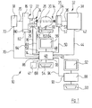
- FIG. 1 shows a first exemplary embodiment of a device 10 for generating radiographic images with a radiation source 12, which generates X-ray radiation.
- the X-radiation is indicated by dashed arrows 14.
- the radiation source 12 includes an X-ray tube 16 of conventional design, which is powered by a controllable high voltage power supply 18 via a supply line 20 with energy.
- the operating parameters of the x-ray tube (tube voltage, beam current, exposure time) are given by control signals, which are given to control inputs of the power supply 18, as will be described in more detail.
- the x-ray radiation 14 generated within the x-ray tube 16 leaves the x-ray tube 16 through an exit window 22 permeable to x-ray radiation. From there, the x-ray radiation 14 passes through a diaphragm system 24 with diaphragms 26, by means of which the beam cross section of the x-ray beam can be adjusted.
- the positions of the apertures 26 are adjusted via a controllable aperture drive unit 28 which has a plurality of different ones Adjustment directions associated actuators may include.
- an image detection unit 32 This can have, for example, a conventional x-ray film or a recording unit providing an electronic image as the actual recording medium.
- a digital detection unit 32 comprises a CCD sensor 34 with an upstream luminescent shield 35.
- the output of the CCD sensor 34 is connected via a line 36 to a readout unit 38.
- the latter provides the necessary voltages and control signals for the operation of the CCD sensor 34 and reads out the image stored in the CCD sensor 34 and transmits it to a computer 40 which is provided for image processing and control purposes.
- Another digital detection unit 32 may include an X-ray sensitive imaging sheet 34.
- the read-out unit 38 is then a storage-sheet read-out unit 38 (scanner), as is commonly used with storage foils.
- the electrical lead 36 is then replaced by the optical readout path of the scanner.
- An interface 42 of the readout unit 38 of the CCD sensor 34 used here is connected via a data transmission line 44 to an interface 46 of the computer 40.
- An interface 48 of the computer 40 in turn is connected via a data transmission line 50 to an interface 52 of the CCD sensor 34, can be controlled via the working parameters of the CCD sensor 34.
- the CCD sensor 34 additionally has a signal generator 53 (eg a memory area) which generates a signal corresponding to the operating settings of the CCD sensor 34 and which also communicates with the computer 40 via the interface 52.
- the computer 40 comprises a keypad 54, via which commands can be entered, and a monitor 56, on which e.g. entered commands or current operating parameters are displayed. Examples of entered commands are z. As operating voltage, beam current and exposure time of the X-ray tube, working voltage and read-out frequency of the CCD sensor, etc .. In this respect, the computer 40 also serves as a control or control computer.
- a data transmission line 60 connects an interface 58 of the computer 40 to an interface 62 of an object positioning unit 64 having a signal generator 63.
- the object positioning unit 64 controls a movable positioning means 66 which is detachably connected to the object 30, for example a denture support by means of electric motors (not shown) in the case of a jaw X-ray image.
- a further interface 68 of the computer 40 is connected via a data transmission line 70 to an interface 72 of the controllable power supply unit 18.
- the computer 40 communicates via an interface 74 via a data transmission line 76 with an interface 78 of the shutter drive unit 28.
- This has a signal generator 29 which can communicate via the interface 78 and provides a position corresponding to the aperture 26 corresponding signal.
- the radiation source 12 comprises a signal generator 80 which controls the operating parameters that determine the resulting X-ray 14, i. Tube voltage, beam current and exposure time, corresponding signals generated.
- An interface 82 of the signal generator 80 is connected via a data transmission line 84 to an interface 86 of the computer 40.
- a documentation device in the form of a documentation computer 88 with keypad 90 and monitor 92 has an interface 93, which is connected via a line 94 to a further interface 96 of the computer 40. It receives from there the various operating parameters of the X-ray device.
- the documentation computer 88 serves to store the operating parameters tube voltage, beam current and exposure time to be specified in accordance with the X-ray ordinance in conjunction with an identifier for the taken picture, for example a recording number assigned to the recording, and the associated patient data, so that the X-ray dose that a patient in the Over time, is permanently documented.
- the above-described controlled components connected to the computer 40 are constructed in a known manner such that the control signals received via a corresponding interface are electronically and / or mechanically converted and the components are adjusted in accordance with these signals.
- a corresponding software is installed, which coordinates the communication with the controllable components connected to the computer 40.
- various operating parameters can be set via the computer 40:
- the controllable power supply 18 receives via the data transmission line 70 and its interface 72 parameters for the tube voltage, the radiation current and the exposure time.
- the interface 78 of the shutter drive unit 28 receives a signal, by means of which the position of the diaphragm is adjusted, so that a certain beam cross-section is obtained.
- the object positioning unit 64 adjusts the position of the object after having received corresponding position signals via its interface 62 and the data transmission line 60.
- the operating and reading the image detection unit 32 controlling signals are given via the interface 42 to the readout unit 38.
- the actual image acquisition takes place: generation of the X-ray light and generation of the radiation image corresponding to the proportion of X-ray transmitted through the object 30.
- the readout unit 38 then reads image signals from the CCD sensor 34, which are transmitted via the data transmission line 44 to the interface 46 of the computer 40 and there converted by appropriate software into a visible image, which is displayed on the monitor 56 and is additionally output to a printer 41.
- the recording is also assigned by the documentation calculator 88 for documentation purposes, a continuous record number.
- the documentation computer 88 From the signals of the signal generator 80, the documentation computer 88 knows the operating parameters of the X-ray source 12, and this now stores the operating parameters together with the recording number and the associated patient data.
- the other adjustable operating parameters positions of the diaphragm drive unit 28, of the object positioning unit 64, operating parameters of the image detection unit 32
- the documentation computer 88 stored.
- the operating parameters associated with a specific recording can also be transferred from the documentation computer 88 to the computer 40, whereby the input of the individual operating parameters can be completely or partially omitted for later recordings and the duration of the setting procedure is significantly shortened.
- the interfaces 72, 78, 62 and 52 of the controllable components thus receive control data, which are transmitted by the computer 88.
- the computer 40 thus also serves as a data switch and coordinates the data flow.
- the data stock of the documentation computer 88 can be taken from target operating parameters for new recordings.
- the individual controllable components are designed such that they report their respective actual operating parameters back to the computer 40.
- the data transmission paths between computer 40 and controllable components are therefore operable in two modes, wherein the actual operating parameters of the radiation source 12 and the other controlled components are transmitted to the computer 40 in the first mode.
- nominal operating parameters are transmitted from the documentation computer 88 via the computer 40 to the radiation source 12 and the other controllable components.
- the respective mode is selected by the computer 40 software controlled. Continuous data exchange of the actual and desired operating parameters enables continuous monitoring of the correct operation of the x-ray device.
- each controllable component can send the received data, which serve as the basis of their setting, in copy. This confirms on the one hand the reception of the data, but on the other hand can also be used to compare the received data with those of the computer 40 or the documentation computer 88 data to be compared.
- the computer 40 stops the activation of the controllable power supply 18, so that no power supply of the x-ray tube 16 takes place.
- a corresponding warning message appears on the monitor 56 of the computer 40, so that the operator receives the information as to which operating parameter or parameters does not correspond to the target specifications.
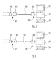
- FIG. 2 shows a second exemplary embodiment of a device for generating radiographic images.
- components corresponding to FIG. 1 are identified by the same reference numerals.
- the only difference to the exemplary embodiment according to FIG. 1 is that the documentation computer 88 is now in direct communication with the signal generator 80 of the radiation source 12.
- Figures 3 and 4 show two embodiments of a data transmission path, which ensure a galvanic separation between the components communicating with each other.
- FIG. 3 shows the data transmission path between the computer 40 and the signal generator 80 of the radiation source 12.
- both the interface 86 of the computer 40 and the interface 82 of the signal generator 80 optocoupler units 102 and 104, which via a light guide 106 with each other in Connection stand. The data transmission thus takes place optically.
- This type of data transmission can also be used in all other data transmission paths shown in FIGS. 1 and 2, resulting in complete electrical isolation of the computers 40 and / or 88 from the components 18, 80, 28, 64 and 32 connected to them.
- FIG. 4 shows a further exemplary embodiment of a galvanically separated data transmission path.
- the interfaces 86 of the computer 40 and 82 of the signal generator 80 respectively radio modem parts 108 and 110, which are suitable for transmitting and receiving radio signals.
- a data transmission path 112 is thus completely bypassed.
- This type of data transmission can also be used for all data transmission paths shown in FIGS. 1 and 2.
- optical data transmission and / or data transmission via radio signal reduces interference factors.
- devices that meet different standards can be easily combined with each other.
Landscapes
- Health & Medical Sciences (AREA)
- Life Sciences & Earth Sciences (AREA)
- Medical Informatics (AREA)
- Engineering & Computer Science (AREA)
- Radiology & Medical Imaging (AREA)
- Molecular Biology (AREA)
- Biophysics (AREA)
- Nuclear Medicine, Radiotherapy & Molecular Imaging (AREA)
- Optics & Photonics (AREA)
- Pathology (AREA)
- Physics & Mathematics (AREA)
- Biomedical Technology (AREA)
- Heart & Thoracic Surgery (AREA)
- High Energy & Nuclear Physics (AREA)
- Surgery (AREA)
- Animal Behavior & Ethology (AREA)
- General Health & Medical Sciences (AREA)
- Public Health (AREA)
- Veterinary Medicine (AREA)
- Dentistry (AREA)
- Oral & Maxillofacial Surgery (AREA)
- Apparatus For Radiation Diagnosis (AREA)
Applications Claiming Priority (1)
| Application Number | Priority Date | Filing Date | Title |
|---|---|---|---|
| DE102005040375A DE102005040375A1 (de) | 2005-08-25 | 2005-08-25 | Vorrichtung zur Erstellung von Durchstrahlungsbildern |
Publications (2)
| Publication Number | Publication Date |
|---|---|
| EP1759636A2 true EP1759636A2 (fr) | 2007-03-07 |
| EP1759636A3 EP1759636A3 (fr) | 2007-05-16 |
Family
ID=37650010
Family Applications (1)
| Application Number | Title | Priority Date | Filing Date |
|---|---|---|---|
| EP06016908A Withdrawn EP1759636A3 (fr) | 2005-08-25 | 2006-08-14 | Appareil de réalisation d'images radiographiques |
Country Status (2)
| Country | Link |
|---|---|
| EP (1) | EP1759636A3 (fr) |
| DE (1) | DE102005040375A1 (fr) |
Families Citing this family (1)
| Publication number | Priority date | Publication date | Assignee | Title |
|---|---|---|---|---|
| DE102007057872A1 (de) * | 2007-11-29 | 2009-06-10 | Sirona Dental Systems Gmbh | Dentales Röntgengerät, Bilderfassungssystem und Verfahren zum Betrieb eines Bilderfassungssystems mit einem dentalen Röntgengerät |
Citations (5)
| Publication number | Priority date | Publication date | Assignee | Title |
|---|---|---|---|---|
| US5121419A (en) | 1986-07-07 | 1992-06-09 | Thomson-Cgr | Computer-aided tomography apparatus |
| EP1041785A2 (fr) | 1999-03-31 | 2000-10-04 | General Electric Company | Démodulateur d'amplitude pour systèmes de tompgraphie assistée par ordinateur |
| US20030118154A1 (en) | 2001-12-15 | 2003-06-26 | Hanns-Ingo Maack | X-ray device with a storage for X-ray exposure parameters |
| US20040092814A1 (en) | 2002-11-08 | 2004-05-13 | Jiang Hsieh | Methods and apparatus for detecting structural, perfusion, and functional abnormalities |
| US20060023832A1 (en) | 2004-07-29 | 2006-02-02 | General Electric Company | Scatter control system and method for computed tomography |
Family Cites Families (3)
| Publication number | Priority date | Publication date | Assignee | Title |
|---|---|---|---|---|
| US6031892A (en) * | 1989-12-05 | 2000-02-29 | University Of Massachusetts Medical Center | System for quantitative radiographic imaging |
| US5276333A (en) * | 1991-11-27 | 1994-01-04 | Eastman Kodak Company | X-ray cassette having removable photographic element |
| DE10216857A1 (de) * | 2002-04-16 | 2003-11-13 | Siemens Ag | Verfahren zur Steuerung einer Röntgeneinrichtung |
-
2005
- 2005-08-25 DE DE102005040375A patent/DE102005040375A1/de not_active Withdrawn
-
2006
- 2006-08-14 EP EP06016908A patent/EP1759636A3/fr not_active Withdrawn
Patent Citations (5)
| Publication number | Priority date | Publication date | Assignee | Title |
|---|---|---|---|---|
| US5121419A (en) | 1986-07-07 | 1992-06-09 | Thomson-Cgr | Computer-aided tomography apparatus |
| EP1041785A2 (fr) | 1999-03-31 | 2000-10-04 | General Electric Company | Démodulateur d'amplitude pour systèmes de tompgraphie assistée par ordinateur |
| US20030118154A1 (en) | 2001-12-15 | 2003-06-26 | Hanns-Ingo Maack | X-ray device with a storage for X-ray exposure parameters |
| US20040092814A1 (en) | 2002-11-08 | 2004-05-13 | Jiang Hsieh | Methods and apparatus for detecting structural, perfusion, and functional abnormalities |
| US20060023832A1 (en) | 2004-07-29 | 2006-02-02 | General Electric Company | Scatter control system and method for computed tomography |
Also Published As
| Publication number | Publication date |
|---|---|
| DE102005040375A1 (de) | 2007-03-01 |
| EP1759636A3 (fr) | 2007-05-16 |
Similar Documents
| Publication | Publication Date | Title |
|---|---|---|
| DE10163583A1 (de) | Verfahren und Vorrichtung zur Belichtung von Röntgenaufnahmen | |
| DE102004042790A1 (de) | Röntgeneinrichtung | |
| DE69023462T2 (de) | Verfahren zur Regelung der Belichtungszeit eines Röntgengerätes, insbesondere für die Mammographie. | |
| DE102004003881A1 (de) | Bildaufnahmevorrichtung | |
| DE102004006552B4 (de) | Verfahren zur Kontrolle eines Hochfrequenz-Leistungsverstärkers, Hochfrequenzeinrichtung, Hochfrequenzkontrolleinrichtung und Magnetresonanztomographiesystem | |
| EP0993239B1 (fr) | Appareil à rayons X | |
| DE60025469T2 (de) | Bilderzeugungsgerät | |
| DE19837442A1 (de) | CT-Gerät | |
| DE102006029327B4 (de) | Systeme, Verfahren und Vorrichtung zur Offsetkorrektur von Röntgenbildern | |
| DE10234465A1 (de) | Verfahren zur Schichthöhenpositionierung | |
| WO2008043672A2 (fr) | Procédé pour contrôler un état de puissance d'un émetteur de rayons x et/ou d'un détecteur de rayons x et système pour mettre en oeuvre ce procédé | |
| DE69801937T2 (de) | Röntgen-Computertomograph | |
| EP1321099B1 (fr) | Appareil à rayons X avec mémoire pour stocker les paramètres de prise de vue des radiographies | |
| DE10353197A1 (de) | Verfahren und Einrichtung zum Korrigieren eines Artefakt durch ein gehaltenes Bild | |
| DE10112792B4 (de) | Verfahren zur Korrektur einer Kalibrierwerte enthaltenden Kalibriertabelle eines CT-Geräts | |
| DE2548531C2 (fr) | ||
| DE102010062459B4 (de) | Verfahren für ein Computertomographiegerät zur Reduzierung der Belastung einer Komponente, Rechenprogramm, Datenträger und Computertomographiegerät | |
| EP0381785A1 (fr) | Dispositif tournant pour la transmission de données | |
| EP1691216A1 (fr) | Système radiographique et méthode d'enregistrement des radiographies dans des feuilles photostimulables | |
| DE102005031901B4 (de) | Verfahren zur Planung einer Untersuchung in einer Magnetresonanzanlage und Magnetresonanzanlage hierfür | |
| EP1759636A2 (fr) | Appareil de réalisation d'images radiographiques | |
| DE102007003380A1 (de) | Vorrichtung und Verfahren für eine medizinische Diagnose | |
| EP0455001B1 (fr) | Arrangement de circuit pour des générateurs de rayons X, en particulier en vue d'applications diagnostiques | |
| DE102012216272A1 (de) | Röntgenfokusjustage | |
| DE102016221205A1 (de) | Verfahren zur Erzeugung von Röntgenbildern und Röntgensystem |
Legal Events
| Date | Code | Title | Description |
|---|---|---|---|
| PUAI | Public reference made under article 153(3) epc to a published international application that has entered the european phase |
Free format text: ORIGINAL CODE: 0009012 |
|
| AK | Designated contracting states |
Kind code of ref document: A2 Designated state(s): AT BE BG CH CY CZ DE DK EE ES FI FR GB GR HU IE IS IT LI LT LU LV MC NL PL PT RO SE SI SK TR |
|
| AX | Request for extension of the european patent |
Extension state: AL BA HR MK YU |
|
| PUAL | Search report despatched |
Free format text: ORIGINAL CODE: 0009013 |
|
| AK | Designated contracting states |
Kind code of ref document: A3 Designated state(s): AT BE BG CH CY CZ DE DK EE ES FI FR GB GR HU IE IS IT LI LT LU LV MC NL PL PT RO SE SI SK TR |
|
| AX | Request for extension of the european patent |
Extension state: AL BA HR MK YU |
|
| 17P | Request for examination filed |
Effective date: 20071116 |
|
| AKX | Designation fees paid |
Designated state(s): AT BE BG CH CY CZ DE DK EE ES FI FR GB GR HU IE IS IT LI LT LU LV MC NL PL PT RO SE SI SK TR |
|
| 17Q | First examination report despatched |
Effective date: 20080117 |
|
| RAP1 | Party data changed (applicant data changed or rights of an application transferred) |
Owner name: DUERR DENTAL AG |
|
| STAA | Information on the status of an ep patent application or granted ep patent |
Free format text: STATUS: THE APPLICATION IS DEEMED TO BE WITHDRAWN |
|
| 18D | Application deemed to be withdrawn |
Effective date: 20120301 |