EP1759948A2 - Kolbenpumpe - Google Patents
Kolbenpumpe Download PDFInfo
- Publication number
- EP1759948A2 EP1759948A2 EP06119239A EP06119239A EP1759948A2 EP 1759948 A2 EP1759948 A2 EP 1759948A2 EP 06119239 A EP06119239 A EP 06119239A EP 06119239 A EP06119239 A EP 06119239A EP 1759948 A2 EP1759948 A2 EP 1759948A2
- Authority
- EP
- European Patent Office
- Prior art keywords
- piston
- cylinder
- filter element
- piston pump
- pump according
- Prior art date
- Legal status (The legal status is an assumption and is not a legal conclusion. Google has not performed a legal analysis and makes no representation as to the accuracy of the status listed.)
- Granted
Links
- 239000012530 fluid Substances 0.000 claims abstract description 9
- 238000009434 installation Methods 0.000 description 2
- 238000007789 sealing Methods 0.000 description 2
- 230000000295 complement effect Effects 0.000 description 1
- 238000010276 construction Methods 0.000 description 1
- 230000001419 dependent effect Effects 0.000 description 1
- 238000011161 development Methods 0.000 description 1
- 230000018109 developmental process Effects 0.000 description 1
Images

Classifications
-
- F—MECHANICAL ENGINEERING; LIGHTING; HEATING; WEAPONS; BLASTING
- F04—POSITIVE - DISPLACEMENT MACHINES FOR LIQUIDS; PUMPS FOR LIQUIDS OR ELASTIC FLUIDS
- F04B—POSITIVE-DISPLACEMENT MACHINES FOR LIQUIDS; PUMPS
- F04B53/00—Component parts, details or accessories not provided for in, or of interest apart from, groups F04B1/00 - F04B23/00 or F04B39/00 - F04B47/00
- F04B53/20—Filtering
-
- B—PERFORMING OPERATIONS; TRANSPORTING
- B60—VEHICLES IN GENERAL
- B60T—VEHICLE BRAKE CONTROL SYSTEMS OR PARTS THEREOF; BRAKE CONTROL SYSTEMS OR PARTS THEREOF, IN GENERAL; ARRANGEMENT OF BRAKING ELEMENTS ON VEHICLES IN GENERAL; PORTABLE DEVICES FOR PREVENTING UNWANTED MOVEMENT OF VEHICLES; VEHICLE MODIFICATIONS TO FACILITATE COOLING OF BRAKES
- B60T8/00—Arrangements for adjusting wheel-braking force to meet varying vehicular or ground-surface conditions, e.g. limiting or varying distribution of braking force
- B60T8/32—Arrangements for adjusting wheel-braking force to meet varying vehicular or ground-surface conditions, e.g. limiting or varying distribution of braking force responsive to a speed condition, e.g. acceleration or deceleration
- B60T8/34—Arrangements for adjusting wheel-braking force to meet varying vehicular or ground-surface conditions, e.g. limiting or varying distribution of braking force responsive to a speed condition, e.g. acceleration or deceleration having a fluid pressure regulator responsive to a speed condition
- B60T8/40—Arrangements for adjusting wheel-braking force to meet varying vehicular or ground-surface conditions, e.g. limiting or varying distribution of braking force responsive to a speed condition, e.g. acceleration or deceleration having a fluid pressure regulator responsive to a speed condition comprising an additional fluid circuit including fluid pressurising means for modifying the pressure of the braking fluid, e.g. including wheel driven pumps for detecting a speed condition, or pumps which are controlled by means independent of the braking system
- B60T8/4031—Pump units characterised by their construction or mounting
Definitions
- the present invention relates to a piston pump for conveying fluids, which has a simple and improved construction.
- the piston pump according to the invention is used in particular in brake systems of vehicles with an active pressure build-up.
- Piston pumps are known from the prior art in different configurations. Piston pumps, which are to be used in particular in braking systems of vehicles, have to have the lowest possible weight and a compact design as possible.
- piston pumps are known, which suck a fluid radially through a radial transverse bore in the piston and perform a pressure chamber via a longitudinal bore in the piston.
- Such pistons have a filter element which is arranged radially on the piston. The filter element is held by means of retaining rings in position.
- the piston pump according to the invention for conveying fluids with the features of claim 1 has the advantage that it can ensure a simple and secure arrangement of a filter element. in this connection According to the invention, furthermore, the number of components can be reduced and furthermore a simple and safe assembly can be made possible.
- the piston pump according to the invention can be made particularly cost-effective due to uncomplicated geometries of the components. This is inventively achieved in that the filter element which filters a sucked fluid, is attached to an inner side of a cylinder. By attachment to the inside of the cylinder, a simple and secure fixation of the filter element can be ensured, in particular during operation of the piston pump.
- the filter element preferably has a first ramp, which is in contact with a second ramp on the piston of the piston pump. If the pump element is preassembled as an assembly, but not yet in a final assembly position, for example in a brake system, the two ramps abut each other, so that the pre-assembled assembly does not fall apart.
- the first ramp of the filter element preferably has an angle between about 10 ° and about 30 °, and in particular an angle of about 20 ° on.
- the second ramp is arranged on the piston on an annular, and outwardly projecting shoulder of the piston.
- the annular projecting shoulder of the piston with the second ramp is more preferably also designed as a contact surface for a seal of the piston.
- a latching connection is formed between the cylinder and the filter element.
- the latching connection between the cylinder and the filter element is preferably formed such that a recess is formed on the inside of the cylinder and on the filter element, a protruding latching element is formed, which is arranged in the assembled state in the recess.
- the recess in the cylinder is formed on a tapered region of the cylinder, in particular on a conical region.
- the piston pump according to the invention is particularly preferably used in a brake system for vehicles, in particular in a brake system with an active pressure build-up, such as an ABS, ESP and / or TCS system.
- an active pressure build-up such as an ABS, ESP and / or TCS system.
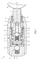
- the piston pump 1 has a piston 2 which has a plurality of transverse bores 3 and a longitudinal bore 4.
- the transverse bores 3 open into the longitudinal bore 4.
- the longitudinal bore 4 is closed by means of an inlet valve 5.
- the inlet valve 5 comprises a cage 10, a spring 11 and a ball 12 for closing the longitudinal bore 4.
- the piston 2 is in a cylinder 8 by means of an eccentric drive 16 in the axial direction X-X back and forth movable.
- the inlet valve 5 closes or releases a connection between the longitudinal bore 4 and a pressure chamber 7.
- an outlet bore 19 is provided, which can be opened or closed by means of an outlet valve 6.
- a provision of the piston 2 by means of a pressure chamber 7 arranged in the return element 17.
- a sealing element 13 seals the pressure chamber 7 against the piston 2 from.
- the outlet valve 6 is arranged in a cover 18.
- the entire piston pump 1 is in turn arranged in a housing 15. It is important that the piston pump 1 can be handled as a preassembled module with cover 18, cylinder 8 and piston 2 and only has to be inserted into the housing 15. This is achieved by the filter element 9 according to the invention.
- Figure 2 shows the piston pump 1 as a preassembled module, which is not yet installed in a housing o. ⁇ .
- the return spring 17 presses against the cage 10 and thus onto the end face of the piston 2 facing the pressure chamber 7.
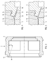
- a first ramp 9b is formed on the filter element 9 , This can be seen in particular from FIGS. 3 to 5.
- the ramp 9b is arranged on a latching element 9a.
- a second run-on region 2b is arranged on the annular projecting region 2a.
- the two casserole areas 2b and 9b are conical.
- a conical region 8a is further provided, in which a recess 8b is formed.
- the recess 8b is formed complementary to the locking element 9a of the filter element 9.
- the locking connection can be particularly easy to be mounted by the conical portion 8a in the cylinder 8 and is also easily solvable.
- the return spring 17 presses the piston 2 in the rightward direction until the second bake area 2b on the annular projecting shoulder 2a of the piston 2 comes into contact with the first casserole area 9b on the filter element 9 (cf. FIG. 5).
- the filter element 9 thus prevents the piston 2 is pushed further by the return spring 17 by the two bevels 2b, 9b accumulated on each other. This condition is shown in FIGS. 2 and 5.
- the filter element 9 in addition to the filter function also provide a function for holding together the piston pump 1 as a preassembled module. Due to the design of the two ramps 2b and 9b, a radial force is additionally exerted on the locking connection between the filter element 9 and the cylinder 8, so that the latching connection is additionally secured by the return spring 17.
- the function of the piston pump 1 according to the invention is as follows. In the suction phase of the pump fluid in the radial direction through the filter element 9, as indicated in Figure 1 by the arrow S, sucked into the transverse bores 3 and fed via the longitudinal bore 4 in the pressure chamber 7.
- the inlet valve 5 is in its open position. When the bottom dead center is reached, the direction of movement of the piston 2 reverses and the inlet valve 5 is closed by the pressure build-up in the pressure chamber 7. This position is shown in FIG.
- the piston 2 is thus moved again in the direction of the outlet valve 6, wherein the pressure in the pressure chamber 7 increases. If the Pressure in the pressure chamber is greater than a spring force of the exhaust valve 6, opens the exhaust valve 6 and pressurized fluid flows through the exhaust port 19 through the open exhaust valve 6 from.
- the piston 2 has reached the top dead center, the direction of movement of the piston reverses again, so that the outlet valve 6 is closed again and the inlet valve 5 opens again.
- the piston pump according to the invention thus has a self-assurance by the connection of the cylinder 8 with the filter element 9 on the inside of the cylinder. This prevents the pre-assembled piston pump from falling apart before final installation in a housing. As a result, according to the invention, the number of parts can be reduced since no additional retaining rings or the like are to be provided on the piston pump. An assembly of the piston pump is particularly simple. Furthermore, the two ramps 2b and 9b provide an additional backup in the preassembled state.
- the angle ⁇ on the filter element 9 is about 20 °. Since the two run-up regions 2b and 9b do not touch each other during operation of the piston pump 1, there is thus no load on the latching connection between the filter element 9 and the cylinder 8 during operation.
- the filter element 9 according to the invention in addition to the filter function also has a backup function against falling apart of the module.
Landscapes
- Engineering & Computer Science (AREA)
- Mechanical Engineering (AREA)
- Physics & Mathematics (AREA)
- Fluid Mechanics (AREA)
- General Engineering & Computer Science (AREA)
- Transportation (AREA)
- Details Of Reciprocating Pumps (AREA)
- Valves And Accessory Devices For Braking Systems (AREA)
- Reciprocating Pumps (AREA)
Abstract
Description
- Die vorliegende Erfindung betrifft eine Kolbenpumpe zur Förderung von Fluiden, welche einen einfachen und verbesserten Aufbau aufweist. Die erfindungsgemäße Kolbenpumpe wird insbesondere in Bremsanlagen von Fahrzeugen mit aktivem Druckaufbau verwendet.
- Kolbenpumpen sind aus dem Stand der Technik in unterschiedlichen Ausgestaltungen bekannt. Kolbenpumpen, welche insbesondere in Bremsanlagen von Fahrzeugen verwendet werden sollen, müssen dabei ein möglichst geringes Gewicht und einen möglichst kompakten Aufbau aufweisen. Hierbei sind Kolbenpumpen bekannt, welche ein Fluid radial durch eine radiale Querbohrung im Kolben ansaugen und über eine Längsbohrung im Kolben einem Druckraum zuführen. Derartige Kolben weisen ein Filterelement auf, welches radial am Kolben angeordnet ist. Das Filterelement wird dabei mittels Sicherungsringen in Position gehalten. Es wäre jedoch wünschenswert, eine Kolbenpumpe mit einem vereinfachten Aufbau und reduziertem Gewicht herzustellen.
- Die erfindungsgemäße Kolbenpumpe zur Förderung von Fluiden mit den Merkmalen des Patentanspruchs 1 weist demgegenüber den Vorteil auf, dass sie eine einfache und sichere Anordnung eines Filterelements sicherstellen kann. Hierbei kann erfindungsgemäß weiterhin die Bauteilezahl reduziert werden und ferner eine einfache und sichere Montage ermöglicht werden. Die erfindungsgemäße Kolbenpumpe kann dabei besonders kostengünstig aufgrund von unkomplizierten Geometrien der Bauteile gefertigt werden. Dies wird erfindungsgemäß dadurch erreicht, dass das Filterelement, welches ein angesaugtes Fluid filtert, an einer Innenseite eines Zylinders befestigt ist. Durch die Befestigung an der Innenseite des Zylinders kann eine einfache und sichere Fixierung des Filterelements insbesondere auch während des Betriebs der Kolbenpumpe sichergestellt werden.
- Die Unteransprüche zeigen bevorzugte Weiterbildungen der Erfindung.
- Um eine besonders einfache Montage und besonders sichere Fixierung des Filterelements an der Innenseite des Zylinders zu ermöglichen, weist das Filterelement vorzugsweise eine erste Auflaufschräge auf, welche sich mit einer zweiten Auflaufschräge am Kolben der Kolbenpumpe in Kontakt befindet. Wenn das Pumpenelement als Baugruppe vormontiert ist, sich jedoch noch nicht in einer endgültigen Montageposition beispielsweise in einer Bremsanlage befindet, liegen die beiden Auflaufschrägen aneinander an, so dass die vormontierte Baugruppe nicht auseinander fällt.
- Die erste Auflaufschräge des Filterelements weist vorzugsweise einen Winkel zwischen ca. 10°und ca. 30°, und insbesondere einen Winkel von ca. 20°, auf.
- Weiter bevorzugt ist die zweite Auflaufschräge am Kolben an einem ringförmigen, und nach außen vorstehenden Absatz des Kolbens angeordnet.
- Der ringförmige vorstehende Absatz des Kolbens mit der zweiten Auflaufschräge ist weiter bevorzugt auch als Anlagefläche für eine Dichtung des Kolbens ausgebildet. Dadurch kann der vorstehende Absatz des Kolbens mehrere Funktionen aufweisen.
- Gemäß einer bevorzugten Ausgestaltung der Erfindung ist zwischen dem Zylinder und dem Filterelement eine Rastverbindung ausgebildet. Dadurch kann eine einfache Montage bzw. Demontage des Filterelements am Zylinder ermöglicht werden. Weiterhin kann dadurch sichergestellt werden, dass die Kolbenpumpe im zusammengebauten Zustand sicher als Baugruppe gehandhabt werden kann und vor einer Endmontage nicht auseinander fällt.
- Die Rastverbindung zwischen dem Zylinder und dem Filterelement ist vorzugsweise derart gebildet, dass an der Innenseite des Zylinders eine Ausnehmung gebildet ist und am Filterelement ein vorstehendes Rastelement ausgebildet ist, welches im zusammengebauten Zustand in der Ausnehmung angeordnet ist.
- Um eine besonders einfache Montage des Filterelements am Innenumfang des Zylinders zu ermöglichen, ist die Ausnehmung im Zylinder an einem sich verjüngenden Bereich des Zylinders, insbesondere an einem konischen Bereich, ausgebildet.
- Die erfindungsgemäße Kolbenpumpe wird besonders bevorzugt in einer Bremsanlage für Fahrzeuge, insbesondere in einer Bremsanlage mit einem aktiven Druckaufbau, wie beispielsweise einem ABS-, ESP- und/oder TCS-System verwendet.
- Nachfolgend wird die Erfindung anhand eines bevorzugten Ausführungsbeispiels in Verbindung mit der Zeichnung beschrieben. In der Zeichnung ist:
- Figur 1
- eine schematische Schnittansicht einer Kolbenpumpe in einem eingebauten Zustand,
- Figur 2
- eine schematische Schnittansicht der Kolbenpumpe in einem zusammengebauten Zustand als vormontierte Baugruppe, wobei die Kolbenpumpe jedoch noch nicht im Gehäuse eingebaut ist,
- Figur 3
- eine schematische Schnittansicht eines in Figur 1 und 2 gezeigten Filterelements,
- Figur 4
- eine vergrößerte, schematische Schnittansicht einer Verbindung zwischen Filterelement und Zylinder im montierten Zustand und
- Figur 5
- eine schematische, vergrößerte Ansicht der Verbindung zwischen dem Zylinder und dem Filterelement im zusammengebauten Zustand der Kolbenpumpe, welche jedoch noch nicht in einem Gehäuse montiert ist.
- Nachfolgend wird unter Bezugnahme auf die Figuren 1 bis 5 eine Kolbenpumpe 1 gemäß einem Ausführungsbeispiel der Erfindung beschrieben.
- Wie in Figur 1 gezeigt, weist die erfindungsgemäße Kolbenpumpe 1 einen Kolben 2 auf, welcher mehrere Querbohrungen 3 und eine Längsbohrung 4 aufweist. Die Querbohrungen 3 münden dabei in die Längsbohrung 4. Die Längsbohrung 4 ist mittels eines Einlassventils 5 verschlossen. Das Einlassventil 5 umfasst einen Käfig 10, eine Feder 11 und eine Kugel 12 zum Verschließen der Längsbohrung 4. Der Kolben 2 ist dabei in einem Zylinder 8 mittels eines Exzenterantriebs 16 in Axialrichtung X-X hin und her bewegbar.
- Das Einlassventil 5 verschließt bzw. gibt eine Verbindung zwischen der Längsbohrung 4 und einem Druckraum 7 frei. Im Zylinder 8 ist eine Auslassbohrung 19 vorgesehen, welche mittels eines Auslassventils 6 freigebbar bzw. verschließbar ist. Eine Rückstellung des Kolbens 2 erfolgt mittels eines im Druckraum 7 angeordneten Rückstellelements 17. Ein Dichtelement 13 dichtet den Druckraum 7 gegen den Kolben 2 ab.
- Am Kolben 2 ist ein nach außen gerichteter ringförmig vorstehender Absatz 2a gebildet, an welchem die Dichtung 13 abdichtet. An der zum Exzenterantrieb 16 gerichteten Seite ist ein weiteres Dichtelement 14 vorgesehen.
- Wie aus Figur 1 ersichtlich ist, ist das Auslassventil 6 in einem Deckel 18 angeordnet. Die gesamte Kolbenpumpe 1 ist ihrerseits in einem Gehäuse 15 angeordnet. Hierbei ist es wichtig, dass die Kolbenpumpe 1 als vormontierte Baugruppe mit Deckel 18, Zylinder 8 und Kolben 2 handhabbar ist und nur in das Gehäuse 15 eingeschoben werden muss. Dies wird erfindungsgemäß durch das Filterelement 9 erreicht.
- Figur 2 zeigt die Kolbenpumpe 1 als vormontierte Baugruppe, welche noch nicht in ein Gehäuse o. ä. eingebaut ist. Wie aus Figur 2 ersichtlich ist, drückt die Rückstellfeder 17 gegen den Käfig 10 und somit auf die dem Druckraum 7 zugewandte Stirnseite des Kolbens 2. Um zu verhindern, dass der Kolben 2 nach rechts herausgedrückt wird, ist am Filterelement 9 eine erste Auflaufschräge 9b ausgebildet. Dies ist insbesondere aus den Figuren 3 bis 5 ersichtlich. Die Auflaufschräge 9b ist dabei an einem Rastelement 9a angeordnet.
- Am Kolben 2 ist am ringförmig vorstehenden Bereich 2a ein zweiter Auflaufbereich 2b angeordnet. Wie aus den Figuren 4 und 5 ersichtlich ist, sind die beiden Auflaufbereiche 2b und 9b konisch ausgebildet.
- Am Zylinder 8 ist weiterhin ein konischer Bereich 8a vorgesehen, in welchem eine Ausnehmung 8b gebildet ist. Die Ausnehmung 8b ist komplementär zum Rastelement 9a des Filterelements 9 gebildet. Im zusammengebauten Zustand der Kolbenpumpe ist das Rastelement 9a dabei in der Ausnehmung 8b aufgenommen und verbindet das Filterelement 9 mit dem Zylinder 8. Die Rastverbindung kann dabei durch den konischen Bereich 8a im Zylinder 8 besonders einfach montiert werden und ist auch wieder einfach lösbar. Beim Vormontieren der Kolbenpumpe 1 wird dabei das Filterelement 9 als letztes Bauteil eingefügt. Wenn das Filterelement 9 am Zylinder 8 verrastet ist, dient das Filterelement 9 als Schutz gegen ein Auseinanderfallen der vormontierten Baugruppe. Wie in den Figuren 2 und 5 gezeigt, drückt die Rückstellfeder 17 den Kolben 2 in Richtung nach rechts so lange, bis der zweite Auflaufbereich 2b am ringförmig vorstehenden Absatz 2a des Kolbens 2 mit dem ersten Auflaufbereich 9b am Filterelement 9 in Kontakt kommt (vgl Figur 5). Das Filterelement 9 verhindert somit, dass der Kolben 2 durch die Rückstellfeder 17 weiter herausgedrückt wird, indem die beiden Auflaufschrägen 2b, 9b aufeinander aufgelaufen sind. Dieser Zustand ist in den Figuren 2 und 5 gezeigt. Somit kann das Filterelement 9 neben der Filterfunktion auch noch eine Funktion für das Zusammenhalten der Kolbenpumpe 1 als vormontierte Baugruppe bereitstellen. Durch die Ausbildung der beiden Auflaufschrägen 2b und 9b wird zusätzlich noch eine radial Kraft auf die Rastverbindung zwischen dem Filterelement 9 und dem Zylinder 8 ausgeübt, so dass die Rastverbindung zusätzlich noch über die Rückstellfeder 17 gesichert ist.
- Wenn die Kolbenpumpe 1 in einem Gehäuse 15 o. ä. eingebaut ist, wie in den Figuren 1 und 4 gezeigt, wird die maximale Auslenkung des Kolbens durch das Exzenterelement 16 bestimmt. Diese Position im unteren Totpunkt ist in den Figuren 1 und 4 dargestellt. Dabei ist kleiner Abstand zwischen den beiden Auflaufschrägen 2b und 9b vorhanden, um zu verhindern, dass der ringförmig vorstehende Absatz 2a ständig gegen das Filterelement 9 schlägt.
- Die Funktion der erfindungsgemäßen Kolbenpumpe 1 ist dabei wie folgt. In der Ansaugphase der Pumpe wird Fluid in radialer Richtung durch das Filterelement 9, wie in Figur 1 durch den Pfeil S angedeutet, in die Querbohrungen 3 angesaugt und über die Längsbohrung 4 in den Druckraum 7 zugeführt. Das Einlassventil 5 ist dabei in seiner geöffneten Position. Wenn der untere Totpunkt erreicht ist, kehrt sich die Bewegungsrichtung des Kolbens 2 um und das Einlassventil 5 wird durch den Druckaufbau im Druckraum 7 geschlossen. Diese Position ist in Figur 1 dargestellt. Der Kolben 2 wird somit wieder in Richtung des Auslassventils 6 bewegt, wobei sich der Druck im Druckraum 7 erhöht. Wenn der Druck im Druckraum größer als eine Federkraft des Auslassventils 6 ist, öffnet das Auslassventil 6 und unter Druck stehendes Fluid strömt durch die Auslassöffnung 19 durch das offene Auslassventil 6 ab. Wenn der Kolben 2 den oberen Totpunkt erreicht hat, kehrt sich die Bewegungsrichtung des Kolbens wieder um, so dass das Auslassventil 6 wieder geschlossen wird und das Einlassventil 5 wieder öffnet.
- Die erfindungsgemäße Kolbenpumpe weist somit eine Selbstsicherung durch die Verbindung des Zylinders 8 mit dem Filterelement 9 an der Innenseite des Zylinders auf. Dadurch wird verhindert, dass die als Baugruppe vormontierte Kolbenpumpe vor einem endgültigen Einbau in ein Gehäuse auseinander fällt. Dadurch kann erfindungsgemäß die Teilezahl reduziert werden, da keine zusätzlichen Sicherungsringe o. ä. an der Kolbenpumpe vorzusehen sind. Eine Montage der Kolbenpumpe ist dabei besonders einfach. Ferner stellen die beiden Auflaufschrägen 2b und 9b eine zusätzliche Sicherung im vormontierten Zustand bereit.
- Der Winkel α an dem Filterelement 9 beträgt ca. 20°. Da sich im Betrieb der Kolbenpumpe 1 die beiden Auflaufbereiche 2b und 9b nicht berühren, ist während des Betriebs somit keinerlei Belastung der Rastverbindung zwischen dem Filterelement 9 und dem Zylinder 8 gegeben. Somit weist das erfindungsgemäße Filterelement 9 neben der Filterfunktion auch noch eine Sicherungsfunktion gegen ein Auseinanderfallen der Baugruppe auf.
Claims (9)
- Kolbenpumpe zur Förderung von Fluiden, umfassend einen Zylinder (8), einen im Zylinder (8) bewegbar angeordneten Kolben (2), ein Rückstellelement (17) für den Kolben, einen Antrieb (16) für den Kolben sowie ein Filterelement (9), welches angesaugtes Fluid filtert, wobei das Filterelement (9) mit dem Zylinder (8) an einer zum Kolben (2) gerichteten Innenseite des Zylinders (8) verbunden ist.
- Kolbenpumpe nach Anspruch 1, dadurch gekennzeichnet, dass das Filterelement (9) eine erste Auflaufschräge (9b) aufweist, welche sich mit einer zweiten Auflaufschräge (2b) des Kolbens (2) in Kontakt befindet, wenn die Kolbenpumpe als eine Baugruppe vormontiert ist.
- Kolbenpumpe nach Anspruch 2, dadurch gekennzeichnet, dass die erste Auflaufschräge (9b) des Filterelements (9) einen Winkel von ca. 10° bis 30°, insbesondere 20° aufweist.
- Filterelement nach Anspruch 2 oder 3, dadurch gekennzeichnet, dass die zweite Auflaufschräge (2b) des Kolbens (2) an einem ringförmigen, radial nach außen vorstehenden Absatz (2a) des Kolbens (2) angeordnet ist.
- Kolbenpumpe nach Anspruch 4, dadurch gekennzeichnet, dass der ringförmige, radial nach außen vorstehende Absatz (2a) des Kolbens (2) eine Anlagefläche für eine Dichtung (13) aufweist.
- Kolbenpumpe nach einem der vorherigen Ansprüche, dadurch gekennzeichnet, dass zwischen dem Zylinder (8) und dem Filterelement (9) eine Rastverbindung (8b, 9a) ausgebildet ist.
- Kolbenpumpe nach Anspruch 6, dadurch gekennzeichnet, dass an einer Innenseite des Zylinders (8) eine Ausnehmung (8b) gebildet ist und am Filterelement (9) ein vorstehendes Rastelement (9a) gebildet ist.
- Kolbenpumpe nach Anspruch 7, dadurch gekennzeichnet, dass die Ausnehmung (8b) des Zylinders (8) an einem sich verjüngenden, insbesondere konischen, Bereich (8a) des Zylinders (8) gebildet ist.
- Bremsanlage für ein Fahrzeug, umfassend eine Kolbenpumpe (1) nach einem der vorhergehenden Ansprüche.
Applications Claiming Priority (1)
| Application Number | Priority Date | Filing Date | Title |
|---|---|---|---|
| DE102005042193A DE102005042193A1 (de) | 2005-09-06 | 2005-09-06 | Kolbenpumpe mit verbessertem Aufbau |
Publications (3)
| Publication Number | Publication Date |
|---|---|
| EP1759948A2 true EP1759948A2 (de) | 2007-03-07 |
| EP1759948A3 EP1759948A3 (de) | 2009-09-16 |
| EP1759948B1 EP1759948B1 (de) | 2011-07-27 |
Family
ID=37491748
Family Applications (1)
| Application Number | Title | Priority Date | Filing Date |
|---|---|---|---|
| EP06119239A Not-in-force EP1759948B1 (de) | 2005-09-06 | 2006-08-21 | Kolbenpumpe |
Country Status (3)
| Country | Link |
|---|---|
| EP (1) | EP1759948B1 (de) |
| AT (1) | ATE517791T1 (de) |
| DE (1) | DE102005042193A1 (de) |
Cited By (2)
| Publication number | Priority date | Publication date | Assignee | Title |
|---|---|---|---|---|
| CN102889206A (zh) * | 2011-07-22 | 2013-01-23 | 罗伯特·博世有限公司 | 用于液压活塞泵的泵元件 |
| CN105863987A (zh) * | 2014-12-04 | 2016-08-17 | 现代摩比斯株式会社 | 用于制动器的活塞泵 |
Families Citing this family (1)
| Publication number | Priority date | Publication date | Assignee | Title |
|---|---|---|---|---|
| DE102010030329A1 (de) | 2010-06-22 | 2011-12-22 | Robert Bosch Gmbh | Kolbenpumpe |
Citations (2)
| Publication number | Priority date | Publication date | Assignee | Title |
|---|---|---|---|---|
| DE19732817A1 (de) | 1997-07-30 | 1999-02-04 | Bosch Gmbh Robert | Kolbenpumpe |
| WO1999006695A1 (de) | 1997-07-30 | 1999-02-11 | Robert Bosch Gmbh | Kolbenpumpe |
Family Cites Families (1)
| Publication number | Priority date | Publication date | Assignee | Title |
|---|---|---|---|---|
| DE10346237A1 (de) * | 2003-02-12 | 2004-09-09 | Continental Teves Ag & Co. Ohg | Kolbenpumpe |
-
2005
- 2005-09-06 DE DE102005042193A patent/DE102005042193A1/de not_active Withdrawn
-
2006
- 2006-08-21 AT AT06119239T patent/ATE517791T1/de active
- 2006-08-21 EP EP06119239A patent/EP1759948B1/de not_active Not-in-force
Patent Citations (2)
| Publication number | Priority date | Publication date | Assignee | Title |
|---|---|---|---|---|
| DE19732817A1 (de) | 1997-07-30 | 1999-02-04 | Bosch Gmbh Robert | Kolbenpumpe |
| WO1999006695A1 (de) | 1997-07-30 | 1999-02-11 | Robert Bosch Gmbh | Kolbenpumpe |
Cited By (2)
| Publication number | Priority date | Publication date | Assignee | Title |
|---|---|---|---|---|
| CN102889206A (zh) * | 2011-07-22 | 2013-01-23 | 罗伯特·博世有限公司 | 用于液压活塞泵的泵元件 |
| CN105863987A (zh) * | 2014-12-04 | 2016-08-17 | 现代摩比斯株式会社 | 用于制动器的活塞泵 |
Also Published As
| Publication number | Publication date |
|---|---|
| EP1759948A3 (de) | 2009-09-16 |
| DE102005042193A1 (de) | 2007-03-08 |
| EP1759948B1 (de) | 2011-07-27 |
| ATE517791T1 (de) | 2011-08-15 |
Similar Documents
| Publication | Publication Date | Title |
|---|---|---|
| EP2205865B1 (de) | Kolbenpumpe zur förderung eines fluids und zugehöriges bremssystem | |
| EP1185794B1 (de) | Kolbenpumpe | |
| WO2007147693A2 (de) | Kolbenpumpe | |
| EP2029891B1 (de) | Kolbenpumpe | |
| WO2012034739A1 (de) | Verfahren zur herstellung einer kolbenpumpe und kolbenpumpe | |
| DE102005042197A1 (de) | Kolbenpumpe mit verbessertem Kolben | |
| EP1774177B1 (de) | Kolbenpumpe mit verbessertem wirkungsgrad | |
| DE102006027555A1 (de) | Kolbenpumpe mit reduziertem Geräusch | |
| EP2086805B1 (de) | Kolbenpumpe | |
| EP1774174B1 (de) | Kolbenpumpe mit kompakter haltevorrichtung für eine rückstellfeder | |
| EP1774176B1 (de) | Kolbenpumpe mit verbesserter druckaufbaudynamik | |
| EP1759948B1 (de) | Kolbenpumpe | |
| DE19854716B4 (de) | Kolbenpumpe | |
| DE102010030342A1 (de) | Kolbenpumpe | |
| DE102010030329A1 (de) | Kolbenpumpe | |
| EP1926909B1 (de) | Kolbenpumpe mit reduziertem schadraum | |
| DE102004037146A1 (de) | Kolbenpumpe mit optimiertem Schadraum | |
| DE102004027506B4 (de) | Kolbenpumpe mit kugelförmigem Kolben | |
| DE102004037145B4 (de) | Kolbenpumpe mit kompaktem Aufbau | |
| DE102016220589A1 (de) | Bremsanlage | |
| WO2006008262A1 (de) | Kolbenpumpe mit verbesserter druckaufbaudynamik | |
| DE102004037101A1 (de) | Kolbenpumpe mit verminderter Leckage | |
| DE102013226052A1 (de) | Kolbenpumpe für eine hydraulische Fahrzeugbremsanlage |
Legal Events
| Date | Code | Title | Description |
|---|---|---|---|
| PUAI | Public reference made under article 153(3) epc to a published international application that has entered the european phase |
Free format text: ORIGINAL CODE: 0009012 |
|
| AK | Designated contracting states |
Kind code of ref document: A2 Designated state(s): AT BE BG CH CY CZ DE DK EE ES FI FR GB GR HU IE IS IT LI LT LU LV MC NL PL PT RO SE SI SK TR |
|
| AX | Request for extension of the european patent |
Extension state: AL BA HR MK YU |
|
| PUAL | Search report despatched |
Free format text: ORIGINAL CODE: 0009013 |
|
| AK | Designated contracting states |
Kind code of ref document: A3 Designated state(s): AT BE BG CH CY CZ DE DK EE ES FI FR GB GR HU IE IS IT LI LT LU LV MC NL PL PT RO SE SI SK TR |
|
| AX | Request for extension of the european patent |
Extension state: AL BA HR MK RS |
|
| 17P | Request for examination filed |
Effective date: 20100316 |
|
| 17Q | First examination report despatched |
Effective date: 20100412 |
|
| AKX | Designation fees paid |
Designated state(s): AT BE BG CH CY CZ DE DK EE ES FI FR GB GR HU IE IS IT LI LT LU LV MC NL PL PT RO SE SI SK TR |
|
| GRAP | Despatch of communication of intention to grant a patent |
Free format text: ORIGINAL CODE: EPIDOSNIGR1 |
|
| RIN1 | Information on inventor provided before grant (corrected) |
Inventor name: BELING, HORST Inventor name: SCHULLER, WOLFGANG Inventor name: SCHUMANN, BEATE Inventor name: BLOSCH, GEORG Inventor name: ZIMMERMANN, MARC |
|
| GRAS | Grant fee paid |
Free format text: ORIGINAL CODE: EPIDOSNIGR3 |
|
| GRAA | (expected) grant |
Free format text: ORIGINAL CODE: 0009210 |
|
| AK | Designated contracting states |
Kind code of ref document: B1 Designated state(s): AT BE BG CH CY CZ DE DK EE ES FI FR GB GR HU IE IS IT LI LT LU LV MC NL PL PT RO SE SI SK TR |
|
| REG | Reference to a national code |
Ref country code: GB Ref legal event code: FG4D Free format text: NOT ENGLISH |
|
| REG | Reference to a national code |
Ref country code: CH Ref legal event code: EP |
|
| REG | Reference to a national code |
Ref country code: DE Ref legal event code: R096 Ref document number: 502006009897 Country of ref document: DE Effective date: 20110915 |
|
| REG | Reference to a national code |
Ref country code: NL Ref legal event code: VDEP Effective date: 20110727 |
|
| PG25 | Lapsed in a contracting state [announced via postgrant information from national office to epo] |
Ref country code: LT Free format text: LAPSE BECAUSE OF FAILURE TO SUBMIT A TRANSLATION OF THE DESCRIPTION OR TO PAY THE FEE WITHIN THE PRESCRIBED TIME-LIMIT Effective date: 20110727 Ref country code: NL Free format text: LAPSE BECAUSE OF FAILURE TO SUBMIT A TRANSLATION OF THE DESCRIPTION OR TO PAY THE FEE WITHIN THE PRESCRIBED TIME-LIMIT Effective date: 20110727 Ref country code: IS Free format text: LAPSE BECAUSE OF FAILURE TO SUBMIT A TRANSLATION OF THE DESCRIPTION OR TO PAY THE FEE WITHIN THE PRESCRIBED TIME-LIMIT Effective date: 20111127 Ref country code: SE Free format text: LAPSE BECAUSE OF FAILURE TO SUBMIT A TRANSLATION OF THE DESCRIPTION OR TO PAY THE FEE WITHIN THE PRESCRIBED TIME-LIMIT Effective date: 20110727 Ref country code: PT Free format text: LAPSE BECAUSE OF FAILURE TO SUBMIT A TRANSLATION OF THE DESCRIPTION OR TO PAY THE FEE WITHIN THE PRESCRIBED TIME-LIMIT Effective date: 20111128 Ref country code: FI Free format text: LAPSE BECAUSE OF FAILURE TO SUBMIT A TRANSLATION OF THE DESCRIPTION OR TO PAY THE FEE WITHIN THE PRESCRIBED TIME-LIMIT Effective date: 20110727 |
|
| BERE | Be: lapsed |
Owner name: ROBERT BOSCH G.M.B.H. Effective date: 20110831 |
|
| PG25 | Lapsed in a contracting state [announced via postgrant information from national office to epo] |
Ref country code: PL Free format text: LAPSE BECAUSE OF FAILURE TO SUBMIT A TRANSLATION OF THE DESCRIPTION OR TO PAY THE FEE WITHIN THE PRESCRIBED TIME-LIMIT Effective date: 20110727 Ref country code: GR Free format text: LAPSE BECAUSE OF FAILURE TO SUBMIT A TRANSLATION OF THE DESCRIPTION OR TO PAY THE FEE WITHIN THE PRESCRIBED TIME-LIMIT Effective date: 20111028 Ref country code: LV Free format text: LAPSE BECAUSE OF FAILURE TO SUBMIT A TRANSLATION OF THE DESCRIPTION OR TO PAY THE FEE WITHIN THE PRESCRIBED TIME-LIMIT Effective date: 20110727 Ref country code: CY Free format text: LAPSE BECAUSE OF FAILURE TO SUBMIT A TRANSLATION OF THE DESCRIPTION OR TO PAY THE FEE WITHIN THE PRESCRIBED TIME-LIMIT Effective date: 20110727 Ref country code: SI Free format text: LAPSE BECAUSE OF FAILURE TO SUBMIT A TRANSLATION OF THE DESCRIPTION OR TO PAY THE FEE WITHIN THE PRESCRIBED TIME-LIMIT Effective date: 20110727 |
|
| REG | Reference to a national code |
Ref country code: IE Ref legal event code: FD4D |
|
| PG25 | Lapsed in a contracting state [announced via postgrant information from national office to epo] |
Ref country code: MC Free format text: LAPSE BECAUSE OF NON-PAYMENT OF DUE FEES Effective date: 20110831 |
|
| REG | Reference to a national code |
Ref country code: CH Ref legal event code: PL |
|
| PG25 | Lapsed in a contracting state [announced via postgrant information from national office to epo] |
Ref country code: SK Free format text: LAPSE BECAUSE OF FAILURE TO SUBMIT A TRANSLATION OF THE DESCRIPTION OR TO PAY THE FEE WITHIN THE PRESCRIBED TIME-LIMIT Effective date: 20110727 Ref country code: IE Free format text: LAPSE BECAUSE OF FAILURE TO SUBMIT A TRANSLATION OF THE DESCRIPTION OR TO PAY THE FEE WITHIN THE PRESCRIBED TIME-LIMIT Effective date: 20110727 Ref country code: CH Free format text: LAPSE BECAUSE OF NON-PAYMENT OF DUE FEES Effective date: 20110831 Ref country code: LI Free format text: LAPSE BECAUSE OF NON-PAYMENT OF DUE FEES Effective date: 20110831 Ref country code: CZ Free format text: LAPSE BECAUSE OF FAILURE TO SUBMIT A TRANSLATION OF THE DESCRIPTION OR TO PAY THE FEE WITHIN THE PRESCRIBED TIME-LIMIT Effective date: 20110727 |
|
| PG25 | Lapsed in a contracting state [announced via postgrant information from national office to epo] |
Ref country code: EE Free format text: LAPSE BECAUSE OF FAILURE TO SUBMIT A TRANSLATION OF THE DESCRIPTION OR TO PAY THE FEE WITHIN THE PRESCRIBED TIME-LIMIT Effective date: 20110727 Ref country code: IT Free format text: LAPSE BECAUSE OF FAILURE TO SUBMIT A TRANSLATION OF THE DESCRIPTION OR TO PAY THE FEE WITHIN THE PRESCRIBED TIME-LIMIT Effective date: 20110727 Ref country code: RO Free format text: LAPSE BECAUSE OF FAILURE TO SUBMIT A TRANSLATION OF THE DESCRIPTION OR TO PAY THE FEE WITHIN THE PRESCRIBED TIME-LIMIT Effective date: 20110727 Ref country code: BE Free format text: LAPSE BECAUSE OF NON-PAYMENT OF DUE FEES Effective date: 20110831 |
|
| PLBE | No opposition filed within time limit |
Free format text: ORIGINAL CODE: 0009261 |
|
| STAA | Information on the status of an ep patent application or granted ep patent |
Free format text: STATUS: NO OPPOSITION FILED WITHIN TIME LIMIT |
|
| PG25 | Lapsed in a contracting state [announced via postgrant information from national office to epo] |
Ref country code: DK Free format text: LAPSE BECAUSE OF FAILURE TO SUBMIT A TRANSLATION OF THE DESCRIPTION OR TO PAY THE FEE WITHIN THE PRESCRIBED TIME-LIMIT Effective date: 20110727 |
|
| 26N | No opposition filed |
Effective date: 20120502 |
|
| REG | Reference to a national code |
Ref country code: DE Ref legal event code: R097 Ref document number: 502006009897 Country of ref document: DE Effective date: 20120502 |
|
| REG | Reference to a national code |
Ref country code: AT Ref legal event code: MM01 Ref document number: 517791 Country of ref document: AT Kind code of ref document: T Effective date: 20110821 |
|
| PG25 | Lapsed in a contracting state [announced via postgrant information from national office to epo] |
Ref country code: AT Free format text: LAPSE BECAUSE OF NON-PAYMENT OF DUE FEES Effective date: 20110821 |
|
| PG25 | Lapsed in a contracting state [announced via postgrant information from national office to epo] |
Ref country code: ES Free format text: LAPSE BECAUSE OF FAILURE TO SUBMIT A TRANSLATION OF THE DESCRIPTION OR TO PAY THE FEE WITHIN THE PRESCRIBED TIME-LIMIT Effective date: 20111107 |
|
| PG25 | Lapsed in a contracting state [announced via postgrant information from national office to epo] |
Ref country code: LU Free format text: LAPSE BECAUSE OF NON-PAYMENT OF DUE FEES Effective date: 20110821 |
|
| PG25 | Lapsed in a contracting state [announced via postgrant information from national office to epo] |
Ref country code: BG Free format text: LAPSE BECAUSE OF FAILURE TO SUBMIT A TRANSLATION OF THE DESCRIPTION OR TO PAY THE FEE WITHIN THE PRESCRIBED TIME-LIMIT Effective date: 20111027 |
|
| PG25 | Lapsed in a contracting state [announced via postgrant information from national office to epo] |
Ref country code: TR Free format text: LAPSE BECAUSE OF FAILURE TO SUBMIT A TRANSLATION OF THE DESCRIPTION OR TO PAY THE FEE WITHIN THE PRESCRIBED TIME-LIMIT Effective date: 20110727 |
|
| PG25 | Lapsed in a contracting state [announced via postgrant information from national office to epo] |
Ref country code: HU Free format text: LAPSE BECAUSE OF FAILURE TO SUBMIT A TRANSLATION OF THE DESCRIPTION OR TO PAY THE FEE WITHIN THE PRESCRIBED TIME-LIMIT Effective date: 20110727 |
|
| PGFP | Annual fee paid to national office [announced via postgrant information from national office to epo] |
Ref country code: FR Payment date: 20130820 Year of fee payment: 8 Ref country code: GB Payment date: 20130823 Year of fee payment: 8 |
|
| GBPC | Gb: european patent ceased through non-payment of renewal fee |
Effective date: 20140821 |
|
| REG | Reference to a national code |
Ref country code: FR Ref legal event code: ST Effective date: 20150430 |
|
| PG25 | Lapsed in a contracting state [announced via postgrant information from national office to epo] |
Ref country code: GB Free format text: LAPSE BECAUSE OF NON-PAYMENT OF DUE FEES Effective date: 20140821 |
|
| PG25 | Lapsed in a contracting state [announced via postgrant information from national office to epo] |
Ref country code: FR Free format text: LAPSE BECAUSE OF NON-PAYMENT OF DUE FEES Effective date: 20140901 |
|
| PGFP | Annual fee paid to national office [announced via postgrant information from national office to epo] |
Ref country code: DE Payment date: 20161027 Year of fee payment: 11 |
|
| REG | Reference to a national code |
Ref country code: DE Ref legal event code: R119 Ref document number: 502006009897 Country of ref document: DE |
|
| PG25 | Lapsed in a contracting state [announced via postgrant information from national office to epo] |
Ref country code: DE Free format text: LAPSE BECAUSE OF NON-PAYMENT OF DUE FEES Effective date: 20180301 |