EP1759948A2 - Pompe à piston - Google Patents
Pompe à piston Download PDFInfo
- Publication number
- EP1759948A2 EP1759948A2 EP06119239A EP06119239A EP1759948A2 EP 1759948 A2 EP1759948 A2 EP 1759948A2 EP 06119239 A EP06119239 A EP 06119239A EP 06119239 A EP06119239 A EP 06119239A EP 1759948 A2 EP1759948 A2 EP 1759948A2
- Authority
- EP
- European Patent Office
- Prior art keywords
- piston
- cylinder
- filter element
- piston pump
- pump according
- Prior art date
- Legal status (The legal status is an assumption and is not a legal conclusion. Google has not performed a legal analysis and makes no representation as to the accuracy of the status listed.)
- Granted
Links
- 239000012530 fluid Substances 0.000 claims abstract description 9
- 238000009434 installation Methods 0.000 description 2
- 238000007789 sealing Methods 0.000 description 2
- 230000000295 complement effect Effects 0.000 description 1
- 238000010276 construction Methods 0.000 description 1
- 230000001419 dependent effect Effects 0.000 description 1
- 238000011161 development Methods 0.000 description 1
- 230000018109 developmental process Effects 0.000 description 1
Images

Classifications
-
- F—MECHANICAL ENGINEERING; LIGHTING; HEATING; WEAPONS; BLASTING
- F04—POSITIVE - DISPLACEMENT MACHINES FOR LIQUIDS; PUMPS FOR LIQUIDS OR ELASTIC FLUIDS
- F04B—POSITIVE-DISPLACEMENT MACHINES FOR LIQUIDS; PUMPS
- F04B53/00—Component parts, details or accessories not provided for in, or of interest apart from, groups F04B1/00 - F04B23/00 or F04B39/00 - F04B47/00
- F04B53/20—Filtering
-
- B—PERFORMING OPERATIONS; TRANSPORTING
- B60—VEHICLES IN GENERAL
- B60T—VEHICLE BRAKE CONTROL SYSTEMS OR PARTS THEREOF; BRAKE CONTROL SYSTEMS OR PARTS THEREOF, IN GENERAL; ARRANGEMENT OF BRAKING ELEMENTS ON VEHICLES IN GENERAL; PORTABLE DEVICES FOR PREVENTING UNWANTED MOVEMENT OF VEHICLES; VEHICLE MODIFICATIONS TO FACILITATE COOLING OF BRAKES
- B60T8/00—Arrangements for adjusting wheel-braking force to meet varying vehicular or ground-surface conditions, e.g. limiting or varying distribution of braking force
- B60T8/32—Arrangements for adjusting wheel-braking force to meet varying vehicular or ground-surface conditions, e.g. limiting or varying distribution of braking force responsive to a speed condition, e.g. acceleration or deceleration
- B60T8/34—Arrangements for adjusting wheel-braking force to meet varying vehicular or ground-surface conditions, e.g. limiting or varying distribution of braking force responsive to a speed condition, e.g. acceleration or deceleration having a fluid pressure regulator responsive to a speed condition
- B60T8/40—Arrangements for adjusting wheel-braking force to meet varying vehicular or ground-surface conditions, e.g. limiting or varying distribution of braking force responsive to a speed condition, e.g. acceleration or deceleration having a fluid pressure regulator responsive to a speed condition comprising an additional fluid circuit including fluid pressurising means for modifying the pressure of the braking fluid, e.g. including wheel driven pumps for detecting a speed condition, or pumps which are controlled by means independent of the braking system
- B60T8/4031—Pump units characterised by their construction or mounting
Definitions
- the present invention relates to a piston pump for conveying fluids, which has a simple and improved construction.
- the piston pump according to the invention is used in particular in brake systems of vehicles with an active pressure build-up.
- Piston pumps are known from the prior art in different configurations. Piston pumps, which are to be used in particular in braking systems of vehicles, have to have the lowest possible weight and a compact design as possible.
- piston pumps are known, which suck a fluid radially through a radial transverse bore in the piston and perform a pressure chamber via a longitudinal bore in the piston.
- Such pistons have a filter element which is arranged radially on the piston. The filter element is held by means of retaining rings in position.
- the piston pump according to the invention for conveying fluids with the features of claim 1 has the advantage that it can ensure a simple and secure arrangement of a filter element. in this connection According to the invention, furthermore, the number of components can be reduced and furthermore a simple and safe assembly can be made possible.
- the piston pump according to the invention can be made particularly cost-effective due to uncomplicated geometries of the components. This is inventively achieved in that the filter element which filters a sucked fluid, is attached to an inner side of a cylinder. By attachment to the inside of the cylinder, a simple and secure fixation of the filter element can be ensured, in particular during operation of the piston pump.
- the filter element preferably has a first ramp, which is in contact with a second ramp on the piston of the piston pump. If the pump element is preassembled as an assembly, but not yet in a final assembly position, for example in a brake system, the two ramps abut each other, so that the pre-assembled assembly does not fall apart.
- the first ramp of the filter element preferably has an angle between about 10 ° and about 30 °, and in particular an angle of about 20 ° on.
- the second ramp is arranged on the piston on an annular, and outwardly projecting shoulder of the piston.
- the annular projecting shoulder of the piston with the second ramp is more preferably also designed as a contact surface for a seal of the piston.
- a latching connection is formed between the cylinder and the filter element.
- the latching connection between the cylinder and the filter element is preferably formed such that a recess is formed on the inside of the cylinder and on the filter element, a protruding latching element is formed, which is arranged in the assembled state in the recess.
- the recess in the cylinder is formed on a tapered region of the cylinder, in particular on a conical region.
- the piston pump according to the invention is particularly preferably used in a brake system for vehicles, in particular in a brake system with an active pressure build-up, such as an ABS, ESP and / or TCS system.
- an active pressure build-up such as an ABS, ESP and / or TCS system.
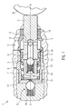
- the piston pump 1 has a piston 2 which has a plurality of transverse bores 3 and a longitudinal bore 4.
- the transverse bores 3 open into the longitudinal bore 4.
- the longitudinal bore 4 is closed by means of an inlet valve 5.
- the inlet valve 5 comprises a cage 10, a spring 11 and a ball 12 for closing the longitudinal bore 4.
- the piston 2 is in a cylinder 8 by means of an eccentric drive 16 in the axial direction X-X back and forth movable.
- the inlet valve 5 closes or releases a connection between the longitudinal bore 4 and a pressure chamber 7.
- an outlet bore 19 is provided, which can be opened or closed by means of an outlet valve 6.
- a provision of the piston 2 by means of a pressure chamber 7 arranged in the return element 17.
- a sealing element 13 seals the pressure chamber 7 against the piston 2 from.
- the outlet valve 6 is arranged in a cover 18.
- the entire piston pump 1 is in turn arranged in a housing 15. It is important that the piston pump 1 can be handled as a preassembled module with cover 18, cylinder 8 and piston 2 and only has to be inserted into the housing 15. This is achieved by the filter element 9 according to the invention.
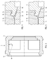
- Figure 2 shows the piston pump 1 as a preassembled module, which is not yet installed in a housing o. ⁇ .
- the return spring 17 presses against the cage 10 and thus onto the end face of the piston 2 facing the pressure chamber 7.
- a first ramp 9b is formed on the filter element 9 , This can be seen in particular from FIGS. 3 to 5.
- the ramp 9b is arranged on a latching element 9a.
- a second run-on region 2b is arranged on the annular projecting region 2a.
- the two casserole areas 2b and 9b are conical.
- a conical region 8a is further provided, in which a recess 8b is formed.
- the recess 8b is formed complementary to the locking element 9a of the filter element 9.
- the locking connection can be particularly easy to be mounted by the conical portion 8a in the cylinder 8 and is also easily solvable.
- the return spring 17 presses the piston 2 in the rightward direction until the second bake area 2b on the annular projecting shoulder 2a of the piston 2 comes into contact with the first casserole area 9b on the filter element 9 (cf. FIG. 5).
- the filter element 9 thus prevents the piston 2 is pushed further by the return spring 17 by the two bevels 2b, 9b accumulated on each other. This condition is shown in FIGS. 2 and 5.
- the filter element 9 in addition to the filter function also provide a function for holding together the piston pump 1 as a preassembled module. Due to the design of the two ramps 2b and 9b, a radial force is additionally exerted on the locking connection between the filter element 9 and the cylinder 8, so that the latching connection is additionally secured by the return spring 17.
- the function of the piston pump 1 according to the invention is as follows. In the suction phase of the pump fluid in the radial direction through the filter element 9, as indicated in Figure 1 by the arrow S, sucked into the transverse bores 3 and fed via the longitudinal bore 4 in the pressure chamber 7.
- the inlet valve 5 is in its open position. When the bottom dead center is reached, the direction of movement of the piston 2 reverses and the inlet valve 5 is closed by the pressure build-up in the pressure chamber 7. This position is shown in FIG.
- the piston 2 is thus moved again in the direction of the outlet valve 6, wherein the pressure in the pressure chamber 7 increases. If the Pressure in the pressure chamber is greater than a spring force of the exhaust valve 6, opens the exhaust valve 6 and pressurized fluid flows through the exhaust port 19 through the open exhaust valve 6 from.
- the piston 2 has reached the top dead center, the direction of movement of the piston reverses again, so that the outlet valve 6 is closed again and the inlet valve 5 opens again.
- the piston pump according to the invention thus has a self-assurance by the connection of the cylinder 8 with the filter element 9 on the inside of the cylinder. This prevents the pre-assembled piston pump from falling apart before final installation in a housing. As a result, according to the invention, the number of parts can be reduced since no additional retaining rings or the like are to be provided on the piston pump. An assembly of the piston pump is particularly simple. Furthermore, the two ramps 2b and 9b provide an additional backup in the preassembled state.
- the angle ⁇ on the filter element 9 is about 20 °. Since the two run-up regions 2b and 9b do not touch each other during operation of the piston pump 1, there is thus no load on the latching connection between the filter element 9 and the cylinder 8 during operation.
- the filter element 9 according to the invention in addition to the filter function also has a backup function against falling apart of the module.
Landscapes
- Engineering & Computer Science (AREA)
- Mechanical Engineering (AREA)
- Physics & Mathematics (AREA)
- Fluid Mechanics (AREA)
- General Engineering & Computer Science (AREA)
- Transportation (AREA)
- Details Of Reciprocating Pumps (AREA)
- Valves And Accessory Devices For Braking Systems (AREA)
- Reciprocating Pumps (AREA)
Applications Claiming Priority (1)
| Application Number | Priority Date | Filing Date | Title |
|---|---|---|---|
| DE102005042193A DE102005042193A1 (de) | 2005-09-06 | 2005-09-06 | Kolbenpumpe mit verbessertem Aufbau |
Publications (3)
| Publication Number | Publication Date |
|---|---|
| EP1759948A2 true EP1759948A2 (fr) | 2007-03-07 |
| EP1759948A3 EP1759948A3 (fr) | 2009-09-16 |
| EP1759948B1 EP1759948B1 (fr) | 2011-07-27 |
Family
ID=37491748
Family Applications (1)
| Application Number | Title | Priority Date | Filing Date |
|---|---|---|---|
| EP06119239A Not-in-force EP1759948B1 (fr) | 2005-09-06 | 2006-08-21 | Pompe à piston |
Country Status (3)
| Country | Link |
|---|---|
| EP (1) | EP1759948B1 (fr) |
| AT (1) | ATE517791T1 (fr) |
| DE (1) | DE102005042193A1 (fr) |
Cited By (2)
| Publication number | Priority date | Publication date | Assignee | Title |
|---|---|---|---|---|
| CN102889206A (zh) * | 2011-07-22 | 2013-01-23 | 罗伯特·博世有限公司 | 用于液压活塞泵的泵元件 |
| CN105863987A (zh) * | 2014-12-04 | 2016-08-17 | 现代摩比斯株式会社 | 用于制动器的活塞泵 |
Families Citing this family (1)
| Publication number | Priority date | Publication date | Assignee | Title |
|---|---|---|---|---|
| DE102010030329A1 (de) | 2010-06-22 | 2011-12-22 | Robert Bosch Gmbh | Kolbenpumpe |
Citations (2)
| Publication number | Priority date | Publication date | Assignee | Title |
|---|---|---|---|---|
| DE19732817A1 (de) | 1997-07-30 | 1999-02-04 | Bosch Gmbh Robert | Kolbenpumpe |
| WO1999006695A1 (fr) | 1997-07-30 | 1999-02-11 | Robert Bosch Gmbh | Pompe a piston |
Family Cites Families (1)
| Publication number | Priority date | Publication date | Assignee | Title |
|---|---|---|---|---|
| DE10346237A1 (de) * | 2003-02-12 | 2004-09-09 | Continental Teves Ag & Co. Ohg | Kolbenpumpe |
-
2005
- 2005-09-06 DE DE102005042193A patent/DE102005042193A1/de not_active Withdrawn
-
2006
- 2006-08-21 AT AT06119239T patent/ATE517791T1/de active
- 2006-08-21 EP EP06119239A patent/EP1759948B1/fr not_active Not-in-force
Patent Citations (2)
| Publication number | Priority date | Publication date | Assignee | Title |
|---|---|---|---|---|
| DE19732817A1 (de) | 1997-07-30 | 1999-02-04 | Bosch Gmbh Robert | Kolbenpumpe |
| WO1999006695A1 (fr) | 1997-07-30 | 1999-02-11 | Robert Bosch Gmbh | Pompe a piston |
Cited By (2)
| Publication number | Priority date | Publication date | Assignee | Title |
|---|---|---|---|---|
| CN102889206A (zh) * | 2011-07-22 | 2013-01-23 | 罗伯特·博世有限公司 | 用于液压活塞泵的泵元件 |
| CN105863987A (zh) * | 2014-12-04 | 2016-08-17 | 现代摩比斯株式会社 | 用于制动器的活塞泵 |
Also Published As
| Publication number | Publication date |
|---|---|
| EP1759948A3 (fr) | 2009-09-16 |
| DE102005042193A1 (de) | 2007-03-08 |
| EP1759948B1 (fr) | 2011-07-27 |
| ATE517791T1 (de) | 2011-08-15 |
Similar Documents
| Publication | Publication Date | Title |
|---|---|---|
| EP2205865B1 (fr) | Pompe à piston destinée au refoulement d'un fluide et système de freinage associé | |
| EP1185794B1 (fr) | Pompe a piston | |
| WO2007147693A2 (fr) | Pompe à piston | |
| EP2029891B1 (fr) | Pompe à piston | |
| WO2012034739A1 (fr) | Procédé de fabrication d'une pompe à piston et pompe à pistons | |
| DE102005042197A1 (de) | Kolbenpumpe mit verbessertem Kolben | |
| EP1774177B1 (fr) | Pompe a piston a rendement ameliore | |
| DE102006027555A1 (de) | Kolbenpumpe mit reduziertem Geräusch | |
| EP2086805B1 (fr) | Pompe à piston | |
| EP1774174B1 (fr) | Pompe a piston comprenant un dispositif de maintien compact pour un ressort de rappel | |
| EP1774176B1 (fr) | Pompe a piston a dynamique de montee en pression amelioree | |
| EP1759948B1 (fr) | Pompe à piston | |
| DE19854716B4 (de) | Kolbenpumpe | |
| DE102010030342A1 (de) | Kolbenpumpe | |
| DE102010030329A1 (de) | Kolbenpumpe | |
| EP1926909B1 (fr) | Pompe a piston a espace mort reduit | |
| DE102004037146A1 (de) | Kolbenpumpe mit optimiertem Schadraum | |
| DE102004027506B4 (de) | Kolbenpumpe mit kugelförmigem Kolben | |
| DE102004037145B4 (de) | Kolbenpumpe mit kompaktem Aufbau | |
| DE102016220589A1 (de) | Bremsanlage | |
| WO2006008262A1 (fr) | Pompe a piston a dynamique de montee en pression amelioree | |
| DE102004037101A1 (de) | Kolbenpumpe mit verminderter Leckage | |
| DE102013226052A1 (de) | Kolbenpumpe für eine hydraulische Fahrzeugbremsanlage |
Legal Events
| Date | Code | Title | Description |
|---|---|---|---|
| PUAI | Public reference made under article 153(3) epc to a published international application that has entered the european phase |
Free format text: ORIGINAL CODE: 0009012 |
|
| AK | Designated contracting states |
Kind code of ref document: A2 Designated state(s): AT BE BG CH CY CZ DE DK EE ES FI FR GB GR HU IE IS IT LI LT LU LV MC NL PL PT RO SE SI SK TR |
|
| AX | Request for extension of the european patent |
Extension state: AL BA HR MK YU |
|
| PUAL | Search report despatched |
Free format text: ORIGINAL CODE: 0009013 |
|
| AK | Designated contracting states |
Kind code of ref document: A3 Designated state(s): AT BE BG CH CY CZ DE DK EE ES FI FR GB GR HU IE IS IT LI LT LU LV MC NL PL PT RO SE SI SK TR |
|
| AX | Request for extension of the european patent |
Extension state: AL BA HR MK RS |
|
| 17P | Request for examination filed |
Effective date: 20100316 |
|
| 17Q | First examination report despatched |
Effective date: 20100412 |
|
| AKX | Designation fees paid |
Designated state(s): AT BE BG CH CY CZ DE DK EE ES FI FR GB GR HU IE IS IT LI LT LU LV MC NL PL PT RO SE SI SK TR |
|
| GRAP | Despatch of communication of intention to grant a patent |
Free format text: ORIGINAL CODE: EPIDOSNIGR1 |
|
| RIN1 | Information on inventor provided before grant (corrected) |
Inventor name: BELING, HORST Inventor name: SCHULLER, WOLFGANG Inventor name: SCHUMANN, BEATE Inventor name: BLOSCH, GEORG Inventor name: ZIMMERMANN, MARC |
|
| GRAS | Grant fee paid |
Free format text: ORIGINAL CODE: EPIDOSNIGR3 |
|
| GRAA | (expected) grant |
Free format text: ORIGINAL CODE: 0009210 |
|
| AK | Designated contracting states |
Kind code of ref document: B1 Designated state(s): AT BE BG CH CY CZ DE DK EE ES FI FR GB GR HU IE IS IT LI LT LU LV MC NL PL PT RO SE SI SK TR |
|
| REG | Reference to a national code |
Ref country code: GB Ref legal event code: FG4D Free format text: NOT ENGLISH |
|
| REG | Reference to a national code |
Ref country code: CH Ref legal event code: EP |
|
| REG | Reference to a national code |
Ref country code: DE Ref legal event code: R096 Ref document number: 502006009897 Country of ref document: DE Effective date: 20110915 |
|
| REG | Reference to a national code |
Ref country code: NL Ref legal event code: VDEP Effective date: 20110727 |
|
| PG25 | Lapsed in a contracting state [announced via postgrant information from national office to epo] |
Ref country code: LT Free format text: LAPSE BECAUSE OF FAILURE TO SUBMIT A TRANSLATION OF THE DESCRIPTION OR TO PAY THE FEE WITHIN THE PRESCRIBED TIME-LIMIT Effective date: 20110727 Ref country code: NL Free format text: LAPSE BECAUSE OF FAILURE TO SUBMIT A TRANSLATION OF THE DESCRIPTION OR TO PAY THE FEE WITHIN THE PRESCRIBED TIME-LIMIT Effective date: 20110727 Ref country code: IS Free format text: LAPSE BECAUSE OF FAILURE TO SUBMIT A TRANSLATION OF THE DESCRIPTION OR TO PAY THE FEE WITHIN THE PRESCRIBED TIME-LIMIT Effective date: 20111127 Ref country code: SE Free format text: LAPSE BECAUSE OF FAILURE TO SUBMIT A TRANSLATION OF THE DESCRIPTION OR TO PAY THE FEE WITHIN THE PRESCRIBED TIME-LIMIT Effective date: 20110727 Ref country code: PT Free format text: LAPSE BECAUSE OF FAILURE TO SUBMIT A TRANSLATION OF THE DESCRIPTION OR TO PAY THE FEE WITHIN THE PRESCRIBED TIME-LIMIT Effective date: 20111128 Ref country code: FI Free format text: LAPSE BECAUSE OF FAILURE TO SUBMIT A TRANSLATION OF THE DESCRIPTION OR TO PAY THE FEE WITHIN THE PRESCRIBED TIME-LIMIT Effective date: 20110727 |
|
| BERE | Be: lapsed |
Owner name: ROBERT BOSCH G.M.B.H. Effective date: 20110831 |
|
| PG25 | Lapsed in a contracting state [announced via postgrant information from national office to epo] |
Ref country code: PL Free format text: LAPSE BECAUSE OF FAILURE TO SUBMIT A TRANSLATION OF THE DESCRIPTION OR TO PAY THE FEE WITHIN THE PRESCRIBED TIME-LIMIT Effective date: 20110727 Ref country code: GR Free format text: LAPSE BECAUSE OF FAILURE TO SUBMIT A TRANSLATION OF THE DESCRIPTION OR TO PAY THE FEE WITHIN THE PRESCRIBED TIME-LIMIT Effective date: 20111028 Ref country code: LV Free format text: LAPSE BECAUSE OF FAILURE TO SUBMIT A TRANSLATION OF THE DESCRIPTION OR TO PAY THE FEE WITHIN THE PRESCRIBED TIME-LIMIT Effective date: 20110727 Ref country code: CY Free format text: LAPSE BECAUSE OF FAILURE TO SUBMIT A TRANSLATION OF THE DESCRIPTION OR TO PAY THE FEE WITHIN THE PRESCRIBED TIME-LIMIT Effective date: 20110727 Ref country code: SI Free format text: LAPSE BECAUSE OF FAILURE TO SUBMIT A TRANSLATION OF THE DESCRIPTION OR TO PAY THE FEE WITHIN THE PRESCRIBED TIME-LIMIT Effective date: 20110727 |
|
| REG | Reference to a national code |
Ref country code: IE Ref legal event code: FD4D |
|
| PG25 | Lapsed in a contracting state [announced via postgrant information from national office to epo] |
Ref country code: MC Free format text: LAPSE BECAUSE OF NON-PAYMENT OF DUE FEES Effective date: 20110831 |
|
| REG | Reference to a national code |
Ref country code: CH Ref legal event code: PL |
|
| PG25 | Lapsed in a contracting state [announced via postgrant information from national office to epo] |
Ref country code: SK Free format text: LAPSE BECAUSE OF FAILURE TO SUBMIT A TRANSLATION OF THE DESCRIPTION OR TO PAY THE FEE WITHIN THE PRESCRIBED TIME-LIMIT Effective date: 20110727 Ref country code: IE Free format text: LAPSE BECAUSE OF FAILURE TO SUBMIT A TRANSLATION OF THE DESCRIPTION OR TO PAY THE FEE WITHIN THE PRESCRIBED TIME-LIMIT Effective date: 20110727 Ref country code: CH Free format text: LAPSE BECAUSE OF NON-PAYMENT OF DUE FEES Effective date: 20110831 Ref country code: LI Free format text: LAPSE BECAUSE OF NON-PAYMENT OF DUE FEES Effective date: 20110831 Ref country code: CZ Free format text: LAPSE BECAUSE OF FAILURE TO SUBMIT A TRANSLATION OF THE DESCRIPTION OR TO PAY THE FEE WITHIN THE PRESCRIBED TIME-LIMIT Effective date: 20110727 |
|
| PG25 | Lapsed in a contracting state [announced via postgrant information from national office to epo] |
Ref country code: EE Free format text: LAPSE BECAUSE OF FAILURE TO SUBMIT A TRANSLATION OF THE DESCRIPTION OR TO PAY THE FEE WITHIN THE PRESCRIBED TIME-LIMIT Effective date: 20110727 Ref country code: IT Free format text: LAPSE BECAUSE OF FAILURE TO SUBMIT A TRANSLATION OF THE DESCRIPTION OR TO PAY THE FEE WITHIN THE PRESCRIBED TIME-LIMIT Effective date: 20110727 Ref country code: RO Free format text: LAPSE BECAUSE OF FAILURE TO SUBMIT A TRANSLATION OF THE DESCRIPTION OR TO PAY THE FEE WITHIN THE PRESCRIBED TIME-LIMIT Effective date: 20110727 Ref country code: BE Free format text: LAPSE BECAUSE OF NON-PAYMENT OF DUE FEES Effective date: 20110831 |
|
| PLBE | No opposition filed within time limit |
Free format text: ORIGINAL CODE: 0009261 |
|
| STAA | Information on the status of an ep patent application or granted ep patent |
Free format text: STATUS: NO OPPOSITION FILED WITHIN TIME LIMIT |
|
| PG25 | Lapsed in a contracting state [announced via postgrant information from national office to epo] |
Ref country code: DK Free format text: LAPSE BECAUSE OF FAILURE TO SUBMIT A TRANSLATION OF THE DESCRIPTION OR TO PAY THE FEE WITHIN THE PRESCRIBED TIME-LIMIT Effective date: 20110727 |
|
| 26N | No opposition filed |
Effective date: 20120502 |
|
| REG | Reference to a national code |
Ref country code: DE Ref legal event code: R097 Ref document number: 502006009897 Country of ref document: DE Effective date: 20120502 |
|
| REG | Reference to a national code |
Ref country code: AT Ref legal event code: MM01 Ref document number: 517791 Country of ref document: AT Kind code of ref document: T Effective date: 20110821 |
|
| PG25 | Lapsed in a contracting state [announced via postgrant information from national office to epo] |
Ref country code: AT Free format text: LAPSE BECAUSE OF NON-PAYMENT OF DUE FEES Effective date: 20110821 |
|
| PG25 | Lapsed in a contracting state [announced via postgrant information from national office to epo] |
Ref country code: ES Free format text: LAPSE BECAUSE OF FAILURE TO SUBMIT A TRANSLATION OF THE DESCRIPTION OR TO PAY THE FEE WITHIN THE PRESCRIBED TIME-LIMIT Effective date: 20111107 |
|
| PG25 | Lapsed in a contracting state [announced via postgrant information from national office to epo] |
Ref country code: LU Free format text: LAPSE BECAUSE OF NON-PAYMENT OF DUE FEES Effective date: 20110821 |
|
| PG25 | Lapsed in a contracting state [announced via postgrant information from national office to epo] |
Ref country code: BG Free format text: LAPSE BECAUSE OF FAILURE TO SUBMIT A TRANSLATION OF THE DESCRIPTION OR TO PAY THE FEE WITHIN THE PRESCRIBED TIME-LIMIT Effective date: 20111027 |
|
| PG25 | Lapsed in a contracting state [announced via postgrant information from national office to epo] |
Ref country code: TR Free format text: LAPSE BECAUSE OF FAILURE TO SUBMIT A TRANSLATION OF THE DESCRIPTION OR TO PAY THE FEE WITHIN THE PRESCRIBED TIME-LIMIT Effective date: 20110727 |
|
| PG25 | Lapsed in a contracting state [announced via postgrant information from national office to epo] |
Ref country code: HU Free format text: LAPSE BECAUSE OF FAILURE TO SUBMIT A TRANSLATION OF THE DESCRIPTION OR TO PAY THE FEE WITHIN THE PRESCRIBED TIME-LIMIT Effective date: 20110727 |
|
| PGFP | Annual fee paid to national office [announced via postgrant information from national office to epo] |
Ref country code: FR Payment date: 20130820 Year of fee payment: 8 Ref country code: GB Payment date: 20130823 Year of fee payment: 8 |
|
| GBPC | Gb: european patent ceased through non-payment of renewal fee |
Effective date: 20140821 |
|
| REG | Reference to a national code |
Ref country code: FR Ref legal event code: ST Effective date: 20150430 |
|
| PG25 | Lapsed in a contracting state [announced via postgrant information from national office to epo] |
Ref country code: GB Free format text: LAPSE BECAUSE OF NON-PAYMENT OF DUE FEES Effective date: 20140821 |
|
| PG25 | Lapsed in a contracting state [announced via postgrant information from national office to epo] |
Ref country code: FR Free format text: LAPSE BECAUSE OF NON-PAYMENT OF DUE FEES Effective date: 20140901 |
|
| PGFP | Annual fee paid to national office [announced via postgrant information from national office to epo] |
Ref country code: DE Payment date: 20161027 Year of fee payment: 11 |
|
| REG | Reference to a national code |
Ref country code: DE Ref legal event code: R119 Ref document number: 502006009897 Country of ref document: DE |
|
| PG25 | Lapsed in a contracting state [announced via postgrant information from national office to epo] |
Ref country code: DE Free format text: LAPSE BECAUSE OF NON-PAYMENT OF DUE FEES Effective date: 20180301 |