EP1760285A2 - Chambre de catalyseur - Google Patents
Chambre de catalyseur Download PDFInfo
- Publication number
- EP1760285A2 EP1760285A2 EP06016100A EP06016100A EP1760285A2 EP 1760285 A2 EP1760285 A2 EP 1760285A2 EP 06016100 A EP06016100 A EP 06016100A EP 06016100 A EP06016100 A EP 06016100A EP 1760285 A2 EP1760285 A2 EP 1760285A2
- Authority
- EP
- European Patent Office
- Prior art keywords
- catalyst
- chamber
- exhaust
- exhaust system
- exhaust gas
- Prior art date
- Legal status (The legal status is an assumption and is not a legal conclusion. Google has not performed a legal analysis and makes no representation as to the accuracy of the status listed.)
- Granted
Links
Images


Classifications
-
- F—MECHANICAL ENGINEERING; LIGHTING; HEATING; WEAPONS; BLASTING
- F01—MACHINES OR ENGINES IN GENERAL; ENGINE PLANTS IN GENERAL; STEAM ENGINES
- F01N—GAS-FLOW SILENCERS OR EXHAUST APPARATUS FOR MACHINES OR ENGINES IN GENERAL; GAS-FLOW SILENCERS OR EXHAUST APPARATUS FOR INTERNAL-COMBUSTION ENGINES
- F01N13/00—Exhaust or silencing apparatus characterised by constructional features
- F01N13/18—Construction facilitating manufacture, assembly, or disassembly
- F01N13/1872—Construction facilitating manufacture, assembly, or disassembly the assembly using stamp-formed parts or otherwise deformed sheet-metal
- F01N13/1877—Construction facilitating manufacture, assembly, or disassembly the assembly using stamp-formed parts or otherwise deformed sheet-metal the channels or tubes thereof being made integrally with the housing
-
- F—MECHANICAL ENGINEERING; LIGHTING; HEATING; WEAPONS; BLASTING
- F01—MACHINES OR ENGINES IN GENERAL; ENGINE PLANTS IN GENERAL; STEAM ENGINES
- F01N—GAS-FLOW SILENCERS OR EXHAUST APPARATUS FOR MACHINES OR ENGINES IN GENERAL; GAS-FLOW SILENCERS OR EXHAUST APPARATUS FOR INTERNAL-COMBUSTION ENGINES
- F01N13/00—Exhaust or silencing apparatus characterised by constructional features
- F01N13/002—Apparatus adapted for particular uses, e.g. for portable devices driven by machines or engines
-
- F—MECHANICAL ENGINEERING; LIGHTING; HEATING; WEAPONS; BLASTING
- F01—MACHINES OR ENGINES IN GENERAL; ENGINE PLANTS IN GENERAL; STEAM ENGINES
- F01N—GAS-FLOW SILENCERS OR EXHAUST APPARATUS FOR MACHINES OR ENGINES IN GENERAL; GAS-FLOW SILENCERS OR EXHAUST APPARATUS FOR INTERNAL-COMBUSTION ENGINES
- F01N13/00—Exhaust or silencing apparatus characterised by constructional features
- F01N13/009—Exhaust or silencing apparatus characterised by constructional features having two or more separate purifying devices arranged in series
- F01N13/0097—Exhaust or silencing apparatus characterised by constructional features having two or more separate purifying devices arranged in series the purifying devices are arranged in a single housing
-
- F—MECHANICAL ENGINEERING; LIGHTING; HEATING; WEAPONS; BLASTING
- F01—MACHINES OR ENGINES IN GENERAL; ENGINE PLANTS IN GENERAL; STEAM ENGINES
- F01N—GAS-FLOW SILENCERS OR EXHAUST APPARATUS FOR MACHINES OR ENGINES IN GENERAL; GAS-FLOW SILENCERS OR EXHAUST APPARATUS FOR INTERNAL-COMBUSTION ENGINES
- F01N13/00—Exhaust or silencing apparatus characterised by constructional features
- F01N13/08—Other arrangements or adaptations of exhaust conduits
- F01N13/082—Other arrangements or adaptations of exhaust conduits of tailpipe, e.g. with means for mixing air with exhaust for exhaust cooling, dilution or evacuation
-
- F—MECHANICAL ENGINEERING; LIGHTING; HEATING; WEAPONS; BLASTING
- F01—MACHINES OR ENGINES IN GENERAL; ENGINE PLANTS IN GENERAL; STEAM ENGINES
- F01N—GAS-FLOW SILENCERS OR EXHAUST APPARATUS FOR MACHINES OR ENGINES IN GENERAL; GAS-FLOW SILENCERS OR EXHAUST APPARATUS FOR INTERNAL-COMBUSTION ENGINES
- F01N13/00—Exhaust or silencing apparatus characterised by constructional features
- F01N13/18—Construction facilitating manufacture, assembly, or disassembly
- F01N13/1838—Construction facilitating manufacture, assembly, or disassembly characterised by the type of connection between parts of exhaust or silencing apparatus, e.g. between housing and tubes, between tubes and baffles
- F01N13/1844—Mechanical joints
- F01N13/1855—Mechanical joints the connection being realised by using bolts, screws, rivets or the like
-
- F—MECHANICAL ENGINEERING; LIGHTING; HEATING; WEAPONS; BLASTING
- F01—MACHINES OR ENGINES IN GENERAL; ENGINE PLANTS IN GENERAL; STEAM ENGINES
- F01N—GAS-FLOW SILENCERS OR EXHAUST APPARATUS FOR MACHINES OR ENGINES IN GENERAL; GAS-FLOW SILENCERS OR EXHAUST APPARATUS FOR INTERNAL-COMBUSTION ENGINES
- F01N13/00—Exhaust or silencing apparatus characterised by constructional features
- F01N13/18—Construction facilitating manufacture, assembly, or disassembly
- F01N13/1888—Construction facilitating manufacture, assembly, or disassembly the housing of the assembly consisting of two or more parts, e.g. two half-shells
-
- F—MECHANICAL ENGINEERING; LIGHTING; HEATING; WEAPONS; BLASTING
- F01—MACHINES OR ENGINES IN GENERAL; ENGINE PLANTS IN GENERAL; STEAM ENGINES
- F01N—GAS-FLOW SILENCERS OR EXHAUST APPARATUS FOR MACHINES OR ENGINES IN GENERAL; GAS-FLOW SILENCERS OR EXHAUST APPARATUS FOR INTERNAL-COMBUSTION ENGINES
- F01N3/00—Exhaust or silencing apparatus having means for purifying, rendering innocuous, or otherwise treating exhaust
- F01N3/08—Exhaust or silencing apparatus having means for purifying, rendering innocuous, or otherwise treating exhaust for rendering innocuous
- F01N3/10—Exhaust or silencing apparatus having means for purifying, rendering innocuous, or otherwise treating exhaust for rendering innocuous by thermal or catalytic conversion of noxious components of exhaust
- F01N3/24—Exhaust or silencing apparatus having means for purifying, rendering innocuous, or otherwise treating exhaust for rendering innocuous by thermal or catalytic conversion of noxious components of exhaust characterised by constructional aspects of converting apparatus
- F01N3/28—Construction of catalytic reactors
- F01N3/2839—Arrangements for mounting catalyst support in housing, e.g. with means for compensating thermal expansion or vibration
-
- F—MECHANICAL ENGINEERING; LIGHTING; HEATING; WEAPONS; BLASTING
- F01—MACHINES OR ENGINES IN GENERAL; ENGINE PLANTS IN GENERAL; STEAM ENGINES
- F01N—GAS-FLOW SILENCERS OR EXHAUST APPARATUS FOR MACHINES OR ENGINES IN GENERAL; GAS-FLOW SILENCERS OR EXHAUST APPARATUS FOR INTERNAL-COMBUSTION ENGINES
- F01N2260/00—Exhaust treating devices having provisions not otherwise provided for
- F01N2260/02—Exhaust treating devices having provisions not otherwise provided for for cooling the device
-
- F—MECHANICAL ENGINEERING; LIGHTING; HEATING; WEAPONS; BLASTING
- F01—MACHINES OR ENGINES IN GENERAL; ENGINE PLANTS IN GENERAL; STEAM ENGINES
- F01N—GAS-FLOW SILENCERS OR EXHAUST APPARATUS FOR MACHINES OR ENGINES IN GENERAL; GAS-FLOW SILENCERS OR EXHAUST APPARATUS FOR INTERNAL-COMBUSTION ENGINES
- F01N2270/00—Mixing air with exhaust gases
- F01N2270/02—Mixing air with exhaust gases for cooling exhaust gases or the apparatus
-
- F—MECHANICAL ENGINEERING; LIGHTING; HEATING; WEAPONS; BLASTING
- F01—MACHINES OR ENGINES IN GENERAL; ENGINE PLANTS IN GENERAL; STEAM ENGINES
- F01N—GAS-FLOW SILENCERS OR EXHAUST APPARATUS FOR MACHINES OR ENGINES IN GENERAL; GAS-FLOW SILENCERS OR EXHAUST APPARATUS FOR INTERNAL-COMBUSTION ENGINES
- F01N2470/00—Structure or shape of exhaust gas passages, pipes or tubes
- F01N2470/30—Tubes with restrictions, i.e. venturi or the like, e.g. for sucking air or measuring mass flow
-
- F—MECHANICAL ENGINEERING; LIGHTING; HEATING; WEAPONS; BLASTING
- F01—MACHINES OR ENGINES IN GENERAL; ENGINE PLANTS IN GENERAL; STEAM ENGINES
- F01N—GAS-FLOW SILENCERS OR EXHAUST APPARATUS FOR MACHINES OR ENGINES IN GENERAL; GAS-FLOW SILENCERS OR EXHAUST APPARATUS FOR INTERNAL-COMBUSTION ENGINES
- F01N2590/00—Exhaust or silencing apparatus adapted to particular use, e.g. for military applications, airplanes, submarines
- F01N2590/06—Exhaust or silencing apparatus adapted to particular use, e.g. for military applications, airplanes, submarines for hand-held tools or portables devices
Definitions
- the invention relates to an exhaust system for an internal combustion engine having at least one catalyst element for converting the combustion exhaust gases.
- This exhaust system can be used for a four-stroke or a two-stroke petrol engine. Since the exhaust system itself has a particularly compact design, it can also be used for hand-operated machines such. As gasoline engine operated cutters, chainsaws, hedge trimmers or the like can be used.
- Generic exhaust systems have an outer housing, which contains at least one rear shell and a front shell. Furthermore, these exhaust systems are equipped with a catalyst chamber in which at least one catalyst element is arranged and is provided with an exhaust gas duct from which exhaust gas is passed out of the catalyst chamber.
- catalysts in the form of coated sheets, expanded metal mesh or wire mesh are used, which have proven to be sufficiently resistant, and which are less heat-stressed by their small depth.
- catalyst chambers are used for the catalysts, from which then the purified exhaust gases are passed through an adjacent exhaust duct directly or indirectly from the outer housing to the outside.
- the invention is therefore the object of the invention to provide an exhaust system with a catalyst chamber, which consists of a few parts and is inexpensive to manufacture. Furthermore, harmful thermal stresses in the components of the exhaust system should be largely avoided.
- the exhaust system for an internal combustion engine has an outer housing, which has at least one rear shell and one front shell contains. So that the combustion exhaust gas from the engine does not enter the environment without being cleaned, a catalyst element is additionally provided in the exhaust system, which is arranged in a catalyst chamber. It goes without saying that a second catalyst chamber can be arranged with a catalyst element within the exhaust system, which can be connected either in parallel or in series with the first catalyst chamber. So that the exhaust gas can escape from the catalyst chamber, an exhaust gas passage is provided, wherein the catalyst chamber simultaneously or additionally forms the exhaust gas passage.
- the catalyst chamber contains at least two chamber halves, wherein the exhaust gas channel is provided in at least one chamber half of the same material and in one piece.
- the exhaust duct is formed by at least one chamber half.
- the exhaust passage is not an additional component, which is arranged by a somewhat degenerate compound on the catalyst chamber, but the catalyst chamber and the exhaust passage form an indivisible unit.
- the exhaust duct can also be formed by both chamber halves. In this case, the exhaust duct may have any cross-sections.
- the exhaust duct is formed in one or more chamber halves. This indentation can be done for example by deep drawing, Senkpressen, punching or other transformations. Since the chamber halves of the catalyst chamber can consist of a piece of sheet metal, the exhaust gas channel can be made simultaneously with the formation of the catalyst chamber. Consequently, no additional manufacturing step for the creation of the exhaust duct is necessary. It also becomes clear that the shape, that is to say the cross-section of the exhaust gas duct and the course of the exhaust gas duct, can be achieved simply by the deformation of the chamber half. For example, the exhaust duct may be curved and / or meander-shaped in order to lengthen the length of the exhaust duct in this way. By a sufficient length of the exhaust duct can Flame formation outside the exhaust system can be avoided, even if the exhaust duct is led directly into the open or into the environment.
- the catalyst chamber can be used.
- the catalyst chamber can be configured in terms of area such that it, for example, fills or closes a complete cross section through the exhaust system in terms of area.
- at least one chamber half is configured circumferentially equal to the cross section of the exhaust system.
- both chamber halves may have the same circumferential shape to close a cross section through the exhaust system.
- an area can be used as a muffler, in which the unconverted exhaust gas passes first.
- This area is provided near the cylinder in the exhaust system. After the exhaust gas has passed through the catalyst chamber and the exhaust duct, it can reach a wider area or be led directly into the environment. Thus, the further area serves primarily as heat protection from the converted exhaust gas.
- This area can also be filled with insulating material such as insulating wool.
- an exhaust gas outlet opening of the exhaust gas channel which is arranged away from a catalyst element end of the channel, terminate in the interior of the exhaust system or directly to an exhaust gas outlet of the outer housing.
- ventilation openings may be provided in the outer housing, in particular in the front shell, whereby cool fresh air enters the exhaust system. It is certainly expedient that this fresh air passes only in a closed area of the exhaust system, which is not filled with the unconverted exhaust gases.
- a nozzle in particular a venturi nozzle / injector nozzle, can additionally be provided at the exhaust gas outlet opening of the exhaust gas duct be provided.
- Venturi nozzle creates a cooling airflow, which not only cools the converted hot exhaust gas but also part of the outer housing.
- the front shell of the outer housing simultaneously forms part of the catalyst chamber. Consequently, in this variant, the front shell of the outer housing could be replaced by a chamber half of the catalyst chamber.
- the exhaust gas outlet opening of the exhaust duct leads directly into the open.
- this variant of the exhaust system comes with very few components. However, since a partial surface of the exhaust system is very hot, which comes directly into contact with the converted exhaust gases, it is advisable to provide an additional heat shield in front of the hot area of the exhaust system.
- This heat shield can for example consist of an aluminum shell or sheet in order to dissipate the existing heat well and thus to achieve an acceptable temperature level.
- At least one catalyst element In order to achieve a high conversion rate in the purification of the exhaust gas, it is advisable to design at least one catalyst element over a large area. If grid-like, perforated plate-like or net-like catalyst elements are used, they can be arranged next to one another in order to achieve a higher stability in the arrangement of the catalyst elements next to one another. Of course, honeycomb catalyst elements could also be used. It is also conceivable that at least two catalyst elements are arranged one behind the other in the flow direction of the exhaust gas. In this context, one speaks of a series connection of the catalyst elements. As already mentioned, it is also possible to arrange two catalyst chambers in succession. In this case, an exhaust gas outlet opening of the first exhaust gas channel can end in the inlet openings of the second catalyst chamber.
- spacers are provided in at least one chamber half. These spacers can also be realized by simple transformations of the chamber halves.
- the catalyst element can be held by the spacers used positively and / or non-positively in the catalyst chamber. If two catalyst elements are provided one behind the other in a catalyst chamber, they can be kept over an additional spacer frame to a predetermined distance.
- the spacer frame itself consists of a metal sheet or the like, which is punched out inside, so that the frame hardly causes a flow resistance between the catalyst elements.
- further spacers may be provided on the spacer frame to increase the sheet thickness of the frame and thus the distance between the catalyst elements.
- this connecting element is to be arranged centrally in the region of the catalyst elements.
- a reversibly releasable connection element can be used, as well as, for example, a screw / nut connection.
- a rivet, a welding point or a Torx connection can be used as a connecting element.
- the nut may be fixed to a chamber half, for example by a welded connection or a positive connection.
- the catalyst chamber is clamped by its edge regions between the rear shell and the front shell of the outer housing.
- the catalyst chamber can be held together.
- the catalyst chamber can be held together even in its edge regions by a bead.
- additional cooling surfaces may be provided on the catalyst chamber. These additional cooling surfaces can be made particularly elegant if at the same time the outer casing of the exhaust system is to be divided into two areas by the catalyst chamber. Thus, in addition to the discharge channel, additional surfaces can be provided in both chamber halves on the left and right sides, by means of which the separation of the outer housing into two regions is simultaneously effected.
- a catalyst element is traversed transversely to the flow direction of the exhaust gas passage.
- a large part of the exhaust gas flows several times through the transversely arranged catalyst element, before it can get into the exhaust duct.
- the exhaust system according to the invention also works with a catalyst element, which is arranged in the same flow direction to the exhaust duct.
- a chamber half which is arranged adjacent to the rear shell with an exhaust gas inlet, have at least one inlet opening, through which the exhaust gas passes into the catalyst chamber.
- at least one outlet opening may be present in the other chamber half, which is arranged adjacent to the front shell, whereby the exhaust gases from the catalyst chamber directly or indirectly gets into the open air.
- the outlet opening is arranged in the front shell. Consequently, the exhaust gas flows more or less once across the exhaust system before it gets cleaned into the environment.
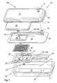
- FIG. 1 shows a first variant of the exhaust system 100 according to the invention.
- the outer housing 10 of the exhaust system 100 is substantially cuboid. This consists in the present case of a front shell 11 and a rear shell 12, wherein the invention is not limited to a two-part housing 10.
- an exhaust gas inlet 16 is provided for the incoming exhaust gas from the internal combustion engine. Since the opening surface of the rear shell 12 and the front shell 11 is closed by the existing catalyst chamber 20, in the front shell 11, a first region 18 and in the rear shell 12, a second region 19, wherein the two regions 18, 19 are separated from each other gas-tight. Thus, the exhaust gas that has entered must enter from the second region 19 through the five circular inlet openings 24 into the catalyst chamber 20.
- the inlet openings 24 are provided for this purpose in the second chamber half 22.
- the actual catalyst chamber 20 is designed cuboid, so that the rectangular catalyst element 33 can be arranged to save space.
- the cuboid recesses of the catalyst chamber 20 have been formed by a forming process in the two chamber halves 21 and 22.
- After the exhaust gas has been converted in the catalyst element 33 it can now enter the exhaust gas channel 23.
- the exhaust gas channel 23 extends over the entire width or length of the catalyst element 33.
- a catalyst-side opening 27 of the exhaust gas channel 23 begins approximately flush with the catalyst element 33.
- two spacers 36 are provided, which are provided between the first chamber half 21 and the catalyst element 33 and between the catalyst element 33 and the second chamber half 22.
- the two chamber halves 21, 22 of the catalyst chamber 20 are held together by the connecting element 32, which is guided by the two spacers 36.
- the reversibly releasable connecting element 32 is configured in two parts in the present case and consists for example of a screw and a nut.
- the converted exhaust gas passes from the exhaust duct 23 through the outlet opening 25.
- the outlet opening 25 is also performed by an exhaust gas outlet 13 in the front shell 11, so that the exhaust gas passes directly into the open.
- the front shell 11 is not unnecessarily heated, isf an additional insulating member 37 between the catalyst chamber 20 and the first chamber half 21 and the front shell 11 is provided.
- This insulating element 37 may for example consist of a cushion of glass fibers.
- FIG. 2 discloses a similar embodiment of the exhaust system 100 according to the invention from FIG. 1.
- the rear shell 12 and the catalyst chamber 20 are of identical construction. Only the outlet opening 25 of the exhaust duct 23 and the front shell 11 have structural changes in comparison to the exhaust system 100 of Figure 1. 2, the outlet opening 25 is open, in which an annular gap is provided, are entrained by the gases from the first region 18 with the exiting exhaust gas stream.
- an injector 26 or a nozzle 26, in particular venturi is used at the exhaust gas outlet 13, whereby a cooling flow is generated in the first region 18 under the front shell 11.
- additional ventilation apertures 14 are provided in the front shell 11, through which fresh air can penetrate into the exhaust system 100.
- the outer housing 10 is constructed identical to the exhaust system 100 of Figure 1, but a differently configured catalyst chamber 20 is used.
- two catalyst elements 33 and 34 are used, which are arranged within the catalyst chamber 20.
- a spacer frame 35 is used.
- This spacer frame 35 consists essentially of a rectangular sheet metal, wherein additional spacers are provided in the corner regions in order to increase the distance between the catalyst elements 33, 34.
- the spacer frame 35 is stamped out in the middle, so that the exhaust gas without flow resistance can pass from the first catalyst element 33 to the second catalyst element 34.
- spacers 36 can be inserted between the catalyst elements and the chamber halves 21, 22.
- a total of six large-scale inlet openings 24 are provided in the first chamber half 21, whereby the previously unconverted exhaust gas enters the catalyst chamber 20. So that the catalyst elements 33, 34 do not come into direct contact with the chamber halves 21, 22 over a large area, additional spacers 31 are formed in the chamber halves 21, 22. This indentation can be done for example by punching or pressing or deep drawing.
- the adjoining the catalyst chamber 20 exhaust duct 23 is configured meandering. This exhaust passage 23 is formed in the first chamber half 21 and the second chamber half 22. It could also be sufficient if the exhaust duct 23 were formed only in a chamber half 21 or 22.
- the first chamber half 21 is configured over a large area, so that in this way the complete cross section of the outer housing 10 is covered.
- the surfaces on the left and right sides of the exhaust duct 23 serve as cooling surfaces 28, whereby additional heat of the exhaust duct 23 can be derived.
- these cooling surfaces 28 can be dispensed with in the second chamber half 22.
- the cooling surfaces 28 may be provided only on the second chamber half 22.
- the outer housing remains by the all-round distance to the channel or to the chamber at a low temperature level.
- the two chamber halves 21, 22 are held by a connecting element 32. Due to the one-point fixation, the catalyst element does not tend to buckle as it expands due to heating.
- This connecting element 32 again consists of a screw and a nut. However, a rivet connection or the like can also be used.
- the two chamber halves 21, 22 can be held together only in their edge regions 29, 30. This can be done for example by the clamping of the chamber halves between the front shell 11 and the rear shell 12. Also, the two chamber halves 21, 22 welded or soldered.
- the exhaust duct 23 in FIG. 3 is meander-shaped and resembles the number "7".
- the catalyst-side opening 27 is not arranged over the entire width of the catalyst elements 33, 34, but overlaps only a small part.
- the converted exhaust gas must pass through this opening 27 into the exhaust duct 23, in order then to be guided through the various bends or creases 23c in the exhaust gas duct 23.
- the length of the exhaust passage 23 can be extended. As a result, a flame outside the exhaust system 100 can be avoided.
- the exhaust system 100 can also be used as an initial, middle or end position for a partially existing exhaust system.
Landscapes
- Engineering & Computer Science (AREA)
- Chemical & Material Sciences (AREA)
- Combustion & Propulsion (AREA)
- Mechanical Engineering (AREA)
- General Engineering & Computer Science (AREA)
- Chemical Kinetics & Catalysis (AREA)
- Health & Medical Sciences (AREA)
- Toxicology (AREA)
- Exhaust Gas After Treatment (AREA)
- Combustion Methods Of Internal-Combustion Engines (AREA)
Applications Claiming Priority (1)
| Application Number | Priority Date | Filing Date | Title |
|---|---|---|---|
| DE202005013804U DE202005013804U1 (de) | 2005-08-31 | 2005-08-31 | Katalysatorkammer |
Publications (3)
| Publication Number | Publication Date |
|---|---|
| EP1760285A2 true EP1760285A2 (fr) | 2007-03-07 |
| EP1760285A3 EP1760285A3 (fr) | 2007-03-14 |
| EP1760285B1 EP1760285B1 (fr) | 2010-05-12 |
Family
ID=37398678
Family Applications (1)
| Application Number | Title | Priority Date | Filing Date |
|---|---|---|---|
| EP06016100A Not-in-force EP1760285B1 (fr) | 2005-08-31 | 2006-08-02 | Chambre de catalyseur |
Country Status (6)
| Country | Link |
|---|---|
| US (1) | US7617675B2 (fr) |
| EP (1) | EP1760285B1 (fr) |
| JP (1) | JP4928872B2 (fr) |
| CN (2) | CN1924314A (fr) |
| AT (1) | ATE467752T1 (fr) |
| DE (2) | DE202005013804U1 (fr) |
Families Citing this family (1)
| Publication number | Priority date | Publication date | Assignee | Title |
|---|---|---|---|---|
| IT1392528B1 (it) * | 2008-12-30 | 2012-03-09 | Emak Spa | Dispositivo per l ' evacuazione dei gas di scarico da un motore a combustione interna per attrezzi portatili da lavoro |
Family Cites Families (19)
| Publication number | Priority date | Publication date | Assignee | Title |
|---|---|---|---|---|
| JPS601685B2 (ja) * | 1977-03-17 | 1985-01-17 | キヤノン株式会社 | 磁気記録方法 |
| US4235843A (en) * | 1978-08-14 | 1980-11-25 | Toyo Kogyo Co., Ltd. | Catalytic converter |
| US4237099A (en) * | 1979-04-25 | 1980-12-02 | General Motors Corporation | Catalytic converter with dual catalyst pellet beds and plenum therebetween |
| US4265332A (en) * | 1979-06-21 | 1981-05-05 | Fmc Corporation | Heat extracting muffler system |
| US4741411A (en) * | 1987-01-14 | 1988-05-03 | Deere & Company | Muffler system |
| DE8817162U1 (de) * | 1987-12-08 | 1993-08-05 | Fa. Andreas Stihl, 71336 Waiblingen | Abgasschalldämpfer für Zweitaktmotoren |
| SE467315B (sv) * | 1987-12-08 | 1992-06-29 | Stihl Maschf Andreas | Avgasljuddaempare foer tvaataktsmotorer, i synnerhet foer baerbara arbetsredskap |
| US4894987A (en) * | 1988-08-19 | 1990-01-23 | Ap Parts Manufacturing Company | Stamp formed muffler and catalytic converter assembly |
| JP2618764B2 (ja) * | 1991-04-26 | 1997-06-11 | 本田技研工業株式会社 | 内燃機関の排気浄化方法及び装置 |
| US5736690A (en) * | 1994-07-18 | 1998-04-07 | Aktiebolaget Electrolux | Muffler with catalytic converter |
| SE504851C2 (sv) * | 1996-01-17 | 1997-05-12 | Electrolux Ab | Katalysatorljuddämpare för mindre förbränningsmotor till t ex bärbara arbetsredskap |
| JPH09228836A (ja) * | 1996-02-23 | 1997-09-02 | Kubota Corp | マフラ冷却装置 |
| SE9703582L (sv) | 1997-10-01 | 1999-04-02 | Electrolux Ab | Katalysatorljuddämpare |
| DE10042145A1 (de) * | 2000-08-26 | 2002-03-07 | Stihl Maschf Andreas | Abgasschalldämpfer für eine Brennkraftmaschine |
| DE10139700B4 (de) * | 2000-10-11 | 2013-01-03 | Andreas Stihl Ag & Co. | Verbrennungsmotor als Antriebsmotor in einem tragbaren, handgeführten Arbeitsgerät |
| DE10239132B4 (de) * | 2002-08-27 | 2012-11-15 | Andreas Stihl Ag & Co | Abgasschalldämpfer |
| JP4381868B2 (ja) * | 2004-04-07 | 2009-12-09 | 本田技研工業株式会社 | エンジン用排気浄化機能付き排気マフラ |
| JP2005325756A (ja) * | 2004-05-13 | 2005-11-24 | Orion Mach Co Ltd | 排ガス浄化装置 |
| JP3955293B2 (ja) * | 2004-08-06 | 2007-08-08 | 株式会社共立 | 内燃エンジンの触媒付きマフラー |
-
2005
- 2005-08-31 DE DE202005013804U patent/DE202005013804U1/de not_active Expired - Lifetime
-
2006
- 2006-08-02 EP EP06016100A patent/EP1760285B1/fr not_active Not-in-force
- 2006-08-02 DE DE502006006925T patent/DE502006006925D1/de active Active
- 2006-08-02 AT AT06016100T patent/ATE467752T1/de active
- 2006-08-21 US US11/466,020 patent/US7617675B2/en not_active Expired - Fee Related
- 2006-08-30 JP JP2006233290A patent/JP4928872B2/ja not_active Expired - Fee Related
- 2006-08-30 CN CNA2006101151875A patent/CN1924314A/zh active Pending
- 2006-08-30 CN CN201010126504A patent/CN101798945A/zh active Pending
Also Published As
| Publication number | Publication date |
|---|---|
| US20080110160A1 (en) | 2008-05-15 |
| CN1924314A (zh) | 2007-03-07 |
| JP4928872B2 (ja) | 2012-05-09 |
| JP2007064223A (ja) | 2007-03-15 |
| DE502006006925D1 (de) | 2010-06-24 |
| US7617675B2 (en) | 2009-11-17 |
| EP1760285A3 (fr) | 2007-03-14 |
| CN101798945A (zh) | 2010-08-11 |
| EP1760285B1 (fr) | 2010-05-12 |
| ATE467752T1 (de) | 2010-05-15 |
| DE202005013804U1 (de) | 2007-01-11 |
Similar Documents
| Publication | Publication Date | Title |
|---|---|---|
| DE69623296T2 (de) | Schalldämpfer mit katalytischem konverter | |
| DE2643240C2 (fr) | ||
| EP2027372B1 (fr) | Filtre à flux secondaire avec rendement de filtre amélioré | |
| DE3335822A1 (de) | Verfahren und vorrichtung zur geraeuschdaempfung an schalldaempfern | |
| DE19900310B4 (de) | Katalytischer Konverter für einen Schalldämpfer eines Kleinmotors | |
| DE4407088A1 (de) | Außenliegender Katalysator für kleine Verbrennungsmotoren | |
| AT396170B (de) | Auspuffanlage fuer zweitakt-brennkraftmaschinen | |
| DE3007866C2 (fr) | ||
| DE19755126B4 (de) | Katalysatoranordnung mit zweisträngiger Abgasführung | |
| EP0542124A1 (fr) | Silencieux | |
| DE60203987T2 (de) | Schalldämpfer kombiniert mit einer Funken-Schutzanordnung | |
| DE10144015A1 (de) | Abgasanlage für mehrzylindrige Verbrennungsmotoren | |
| EP1760285B1 (fr) | Chambre de catalyseur | |
| DE102019217853A1 (de) | Agr-kühler | |
| EP1559882B1 (fr) | Dispositif de purification des gaz d'échappement et procédé de fabrication d'un dispositif de purification des gaz d'échappement | |
| EP1486649B1 (fr) | Catalyseur et procédé pour sa fabrication | |
| DE3015444A1 (de) | Auspuffschalldaempfer | |
| DE202005007861U1 (de) | Mäanderkatalysator | |
| DE19501360C2 (de) | Katalysatorbauteil | |
| EP0666408A1 (fr) | Silencieux, en particulier silencieux d'échappement pour un appareil de chauffage pour véhicule, indépendant du moteur | |
| DE10359073A1 (de) | Abgaskrümmer | |
| DE102005044442B4 (de) | Abgasschalldämpfer | |
| DE102024129766A1 (de) | Abgasanlage mit einem Zweitakt-Motor sowie deren Verwendung | |
| EP1431528A2 (fr) | Dispositif de purification des gaz d'échappement | |
| DE102021115392A1 (de) | Schalldämpfer für eine Abgasanlage einer Brennkraftmaschine |
Legal Events
| Date | Code | Title | Description |
|---|---|---|---|
| PUAI | Public reference made under article 153(3) epc to a published international application that has entered the european phase |
Free format text: ORIGINAL CODE: 0009012 |
|
| PUAL | Search report despatched |
Free format text: ORIGINAL CODE: 0009013 |
|
| AK | Designated contracting states |
Kind code of ref document: A2 Designated state(s): AT BE BG CH CY CZ DE DK EE ES FI FR GB GR HU IE IS IT LI LT LU LV MC NL PL PT RO SE SI SK TR |
|
| AX | Request for extension of the european patent |
Extension state: AL BA HR MK YU |
|
| AK | Designated contracting states |
Kind code of ref document: A3 Designated state(s): AT BE BG CH CY CZ DE DK EE ES FI FR GB GR HU IE IS IT LI LT LU LV MC NL PL PT RO SE SI SK TR |
|
| AX | Request for extension of the european patent |
Extension state: AL BA HR MK YU |
|
| 17P | Request for examination filed |
Effective date: 20070504 |
|
| 17Q | First examination report despatched |
Effective date: 20070620 |
|
| AKX | Designation fees paid |
Designated state(s): AT BE BG CH CY CZ DE DK EE ES FI FR GB GR HU IE IS IT LI LT LU LV MC NL PL PT RO SE SI SK TR |
|
| GRAP | Despatch of communication of intention to grant a patent |
Free format text: ORIGINAL CODE: EPIDOSNIGR1 |
|
| GRAS | Grant fee paid |
Free format text: ORIGINAL CODE: EPIDOSNIGR3 |
|
| GRAA | (expected) grant |
Free format text: ORIGINAL CODE: 0009210 |
|
| AK | Designated contracting states |
Kind code of ref document: B1 Designated state(s): AT BE BG CH CY CZ DE DK EE ES FI FR GB GR HU IE IS IT LI LT LU LV MC NL PL PT RO SE SI SK TR |
|
| REG | Reference to a national code |
Ref country code: GB Ref legal event code: FG4D Free format text: NOT ENGLISH |
|
| REG | Reference to a national code |
Ref country code: CH Ref legal event code: EP |
|
| REG | Reference to a national code |
Ref country code: IE Ref legal event code: FG4D Free format text: LANGUAGE OF EP DOCUMENT: GERMAN |
|
| REF | Corresponds to: |
Ref document number: 502006006925 Country of ref document: DE Date of ref document: 20100624 Kind code of ref document: P |
|
| REG | Reference to a national code |
Ref country code: NL Ref legal event code: VDEP Effective date: 20100512 |
|
| LTIE | Lt: invalidation of european patent or patent extension |
Effective date: 20100512 |
|
| PG25 | Lapsed in a contracting state [announced via postgrant information from national office to epo] |
Ref country code: LT Free format text: LAPSE BECAUSE OF FAILURE TO SUBMIT A TRANSLATION OF THE DESCRIPTION OR TO PAY THE FEE WITHIN THE PRESCRIBED TIME-LIMIT Effective date: 20100512 Ref country code: ES Free format text: LAPSE BECAUSE OF FAILURE TO SUBMIT A TRANSLATION OF THE DESCRIPTION OR TO PAY THE FEE WITHIN THE PRESCRIBED TIME-LIMIT Effective date: 20100823 Ref country code: SE Free format text: LAPSE BECAUSE OF FAILURE TO SUBMIT A TRANSLATION OF THE DESCRIPTION OR TO PAY THE FEE WITHIN THE PRESCRIBED TIME-LIMIT Effective date: 20100512 Ref country code: NL Free format text: LAPSE BECAUSE OF FAILURE TO SUBMIT A TRANSLATION OF THE DESCRIPTION OR TO PAY THE FEE WITHIN THE PRESCRIBED TIME-LIMIT Effective date: 20100512 |
|
| PG25 | Lapsed in a contracting state [announced via postgrant information from national office to epo] |
Ref country code: SI Free format text: LAPSE BECAUSE OF FAILURE TO SUBMIT A TRANSLATION OF THE DESCRIPTION OR TO PAY THE FEE WITHIN THE PRESCRIBED TIME-LIMIT Effective date: 20100512 Ref country code: FI Free format text: LAPSE BECAUSE OF FAILURE TO SUBMIT A TRANSLATION OF THE DESCRIPTION OR TO PAY THE FEE WITHIN THE PRESCRIBED TIME-LIMIT Effective date: 20100512 Ref country code: IS Free format text: LAPSE BECAUSE OF FAILURE TO SUBMIT A TRANSLATION OF THE DESCRIPTION OR TO PAY THE FEE WITHIN THE PRESCRIBED TIME-LIMIT Effective date: 20100912 Ref country code: LV Free format text: LAPSE BECAUSE OF FAILURE TO SUBMIT A TRANSLATION OF THE DESCRIPTION OR TO PAY THE FEE WITHIN THE PRESCRIBED TIME-LIMIT Effective date: 20100512 |
|
| REG | Reference to a national code |
Ref country code: IE Ref legal event code: FD4D |
|
| PG25 | Lapsed in a contracting state [announced via postgrant information from national office to epo] |
Ref country code: PL Free format text: LAPSE BECAUSE OF FAILURE TO SUBMIT A TRANSLATION OF THE DESCRIPTION OR TO PAY THE FEE WITHIN THE PRESCRIBED TIME-LIMIT Effective date: 20100512 Ref country code: GR Free format text: LAPSE BECAUSE OF FAILURE TO SUBMIT A TRANSLATION OF THE DESCRIPTION OR TO PAY THE FEE WITHIN THE PRESCRIBED TIME-LIMIT Effective date: 20100813 Ref country code: CY Free format text: LAPSE BECAUSE OF FAILURE TO SUBMIT A TRANSLATION OF THE DESCRIPTION OR TO PAY THE FEE WITHIN THE PRESCRIBED TIME-LIMIT Effective date: 20100512 |
|
| PG25 | Lapsed in a contracting state [announced via postgrant information from national office to epo] |
Ref country code: EE Free format text: LAPSE BECAUSE OF FAILURE TO SUBMIT A TRANSLATION OF THE DESCRIPTION OR TO PAY THE FEE WITHIN THE PRESCRIBED TIME-LIMIT Effective date: 20100512 Ref country code: PT Free format text: LAPSE BECAUSE OF FAILURE TO SUBMIT A TRANSLATION OF THE DESCRIPTION OR TO PAY THE FEE WITHIN THE PRESCRIBED TIME-LIMIT Effective date: 20100913 Ref country code: IE Free format text: LAPSE BECAUSE OF FAILURE TO SUBMIT A TRANSLATION OF THE DESCRIPTION OR TO PAY THE FEE WITHIN THE PRESCRIBED TIME-LIMIT Effective date: 20100512 Ref country code: DK Free format text: LAPSE BECAUSE OF FAILURE TO SUBMIT A TRANSLATION OF THE DESCRIPTION OR TO PAY THE FEE WITHIN THE PRESCRIBED TIME-LIMIT Effective date: 20100512 |
|
| BERE | Be: lapsed |
Owner name: DOLMAR G.M.B.H. Effective date: 20100831 |
|
| PG25 | Lapsed in a contracting state [announced via postgrant information from national office to epo] |
Ref country code: RO Free format text: LAPSE BECAUSE OF FAILURE TO SUBMIT A TRANSLATION OF THE DESCRIPTION OR TO PAY THE FEE WITHIN THE PRESCRIBED TIME-LIMIT Effective date: 20100512 Ref country code: SK Free format text: LAPSE BECAUSE OF FAILURE TO SUBMIT A TRANSLATION OF THE DESCRIPTION OR TO PAY THE FEE WITHIN THE PRESCRIBED TIME-LIMIT Effective date: 20100512 Ref country code: CZ Free format text: LAPSE BECAUSE OF FAILURE TO SUBMIT A TRANSLATION OF THE DESCRIPTION OR TO PAY THE FEE WITHIN THE PRESCRIBED TIME-LIMIT Effective date: 20100512 |
|
| PLBE | No opposition filed within time limit |
Free format text: ORIGINAL CODE: 0009261 |
|
| STAA | Information on the status of an ep patent application or granted ep patent |
Free format text: STATUS: NO OPPOSITION FILED WITHIN TIME LIMIT |
|
| PG25 | Lapsed in a contracting state [announced via postgrant information from national office to epo] |
Ref country code: IT Free format text: LAPSE BECAUSE OF FAILURE TO SUBMIT A TRANSLATION OF THE DESCRIPTION OR TO PAY THE FEE WITHIN THE PRESCRIBED TIME-LIMIT Effective date: 20100512 Ref country code: MC Free format text: LAPSE BECAUSE OF NON-PAYMENT OF DUE FEES Effective date: 20100831 |
|
| REG | Reference to a national code |
Ref country code: CH Ref legal event code: PL |
|
| 26N | No opposition filed |
Effective date: 20110215 |
|
| GBPC | Gb: european patent ceased through non-payment of renewal fee |
Effective date: 20100812 |
|
| PG25 | Lapsed in a contracting state [announced via postgrant information from national office to epo] |
Ref country code: CH Free format text: LAPSE BECAUSE OF NON-PAYMENT OF DUE FEES Effective date: 20100831 Ref country code: LI Free format text: LAPSE BECAUSE OF NON-PAYMENT OF DUE FEES Effective date: 20100831 |
|
| REG | Reference to a national code |
Ref country code: FR Ref legal event code: ST Effective date: 20110502 |
|
| REG | Reference to a national code |
Ref country code: DE Ref legal event code: R097 Ref document number: 502006006925 Country of ref document: DE Effective date: 20110214 |
|
| PG25 | Lapsed in a contracting state [announced via postgrant information from national office to epo] |
Ref country code: BE Free format text: LAPSE BECAUSE OF NON-PAYMENT OF DUE FEES Effective date: 20100831 Ref country code: FR Free format text: LAPSE BECAUSE OF NON-PAYMENT OF DUE FEES Effective date: 20100831 |
|
| PG25 | Lapsed in a contracting state [announced via postgrant information from national office to epo] |
Ref country code: GB Free format text: LAPSE BECAUSE OF NON-PAYMENT OF DUE FEES Effective date: 20100812 |
|
| PG25 | Lapsed in a contracting state [announced via postgrant information from national office to epo] |
Ref country code: HU Free format text: LAPSE BECAUSE OF FAILURE TO SUBMIT A TRANSLATION OF THE DESCRIPTION OR TO PAY THE FEE WITHIN THE PRESCRIBED TIME-LIMIT Effective date: 20101113 Ref country code: LU Free format text: LAPSE BECAUSE OF NON-PAYMENT OF DUE FEES Effective date: 20100802 Ref country code: BG Free format text: LAPSE BECAUSE OF FAILURE TO SUBMIT A TRANSLATION OF THE DESCRIPTION OR TO PAY THE FEE WITHIN THE PRESCRIBED TIME-LIMIT Effective date: 20100512 |
|
| PG25 | Lapsed in a contracting state [announced via postgrant information from national office to epo] |
Ref country code: TR Free format text: LAPSE BECAUSE OF FAILURE TO SUBMIT A TRANSLATION OF THE DESCRIPTION OR TO PAY THE FEE WITHIN THE PRESCRIBED TIME-LIMIT Effective date: 20100512 |
|
| REG | Reference to a national code |
Ref country code: AT Ref legal event code: MM01 Ref document number: 467752 Country of ref document: AT Kind code of ref document: T Effective date: 20110802 |
|
| PG25 | Lapsed in a contracting state [announced via postgrant information from national office to epo] |
Ref country code: AT Free format text: LAPSE BECAUSE OF NON-PAYMENT OF DUE FEES Effective date: 20110802 |
|
| PG25 | Lapsed in a contracting state [announced via postgrant information from national office to epo] |
Ref country code: BG Free format text: LAPSE BECAUSE OF FAILURE TO SUBMIT A TRANSLATION OF THE DESCRIPTION OR TO PAY THE FEE WITHIN THE PRESCRIBED TIME-LIMIT Effective date: 20100812 |
|
| PGFP | Annual fee paid to national office [announced via postgrant information from national office to epo] |
Ref country code: DE Payment date: 20170921 Year of fee payment: 12 |
|
| REG | Reference to a national code |
Ref country code: DE Ref legal event code: R119 Ref document number: 502006006925 Country of ref document: DE |
|
| PG25 | Lapsed in a contracting state [announced via postgrant information from national office to epo] |
Ref country code: DE Free format text: LAPSE BECAUSE OF NON-PAYMENT OF DUE FEES Effective date: 20190301 |