EP1760337A2 - Kugelgelenk - Google Patents
Kugelgelenk Download PDFInfo
- Publication number
- EP1760337A2 EP1760337A2 EP06023453A EP06023453A EP1760337A2 EP 1760337 A2 EP1760337 A2 EP 1760337A2 EP 06023453 A EP06023453 A EP 06023453A EP 06023453 A EP06023453 A EP 06023453A EP 1760337 A2 EP1760337 A2 EP 1760337A2
- Authority
- EP
- European Patent Office
- Prior art keywords
- wall
- receiving space
- ball joint
- ball
- joint according
- Prior art date
- Legal status (The legal status is an assumption and is not a legal conclusion. Google has not performed a legal analysis and makes no representation as to the accuracy of the status listed.)
- Withdrawn
Links
Images

Classifications
-
- F—MECHANICAL ENGINEERING; LIGHTING; HEATING; WEAPONS; BLASTING
- F16—ENGINEERING ELEMENTS AND UNITS; GENERAL MEASURES FOR PRODUCING AND MAINTAINING EFFECTIVE FUNCTIONING OF MACHINES OR INSTALLATIONS; THERMAL INSULATION IN GENERAL
- F16C—SHAFTS; FLEXIBLE SHAFTS; ELEMENTS OR CRANKSHAFT MECHANISMS; ROTARY BODIES OTHER THAN GEARING ELEMENTS; BEARINGS
- F16C11/00—Pivots; Pivotal connections
- F16C11/04—Pivotal connections
- F16C11/06—Ball-joints; Other joints having more than one degree of angular freedom, i.e. universal joints
- F16C11/0619—Ball-joints; Other joints having more than one degree of angular freedom, i.e. universal joints the female part comprising a blind socket receiving the male part
- F16C11/0623—Construction or details of the socket member
- F16C11/0642—Special features of the plug or cover on the blind end of the socket
-
- F—MECHANICAL ENGINEERING; LIGHTING; HEATING; WEAPONS; BLASTING
- F16—ENGINEERING ELEMENTS AND UNITS; GENERAL MEASURES FOR PRODUCING AND MAINTAINING EFFECTIVE FUNCTIONING OF MACHINES OR INSTALLATIONS; THERMAL INSULATION IN GENERAL
- F16C—SHAFTS; FLEXIBLE SHAFTS; ELEMENTS OR CRANKSHAFT MECHANISMS; ROTARY BODIES OTHER THAN GEARING ELEMENTS; BEARINGS
- F16C11/00—Pivots; Pivotal connections
- F16C11/04—Pivotal connections
- F16C11/06—Ball-joints; Other joints having more than one degree of angular freedom, i.e. universal joints
- F16C11/0619—Ball-joints; Other joints having more than one degree of angular freedom, i.e. universal joints the female part comprising a blind socket receiving the male part
- F16C11/0623—Construction or details of the socket member
- F16C11/0628—Construction or details of the socket member with linings
-
- F—MECHANICAL ENGINEERING; LIGHTING; HEATING; WEAPONS; BLASTING
- F16—ENGINEERING ELEMENTS AND UNITS; GENERAL MEASURES FOR PRODUCING AND MAINTAINING EFFECTIVE FUNCTIONING OF MACHINES OR INSTALLATIONS; THERMAL INSULATION IN GENERAL
- F16C—SHAFTS; FLEXIBLE SHAFTS; ELEMENTS OR CRANKSHAFT MECHANISMS; ROTARY BODIES OTHER THAN GEARING ELEMENTS; BEARINGS
- F16C11/00—Pivots; Pivotal connections
- F16C11/04—Pivotal connections
- F16C11/06—Ball-joints; Other joints having more than one degree of angular freedom, i.e. universal joints
- F16C11/0619—Ball-joints; Other joints having more than one degree of angular freedom, i.e. universal joints the female part comprising a blind socket receiving the male part
- F16C11/0623—Construction or details of the socket member
- F16C11/0647—Special features relating to adjustment for wear or play; Wear indicators
-
- F—MECHANICAL ENGINEERING; LIGHTING; HEATING; WEAPONS; BLASTING
- F16—ENGINEERING ELEMENTS AND UNITS; GENERAL MEASURES FOR PRODUCING AND MAINTAINING EFFECTIVE FUNCTIONING OF MACHINES OR INSTALLATIONS; THERMAL INSULATION IN GENERAL
- F16C—SHAFTS; FLEXIBLE SHAFTS; ELEMENTS OR CRANKSHAFT MECHANISMS; ROTARY BODIES OTHER THAN GEARING ELEMENTS; BEARINGS
- F16C11/00—Pivots; Pivotal connections
- F16C11/04—Pivotal connections
- F16C11/06—Ball-joints; Other joints having more than one degree of angular freedom, i.e. universal joints
- F16C11/0685—Manufacture of ball-joints and parts thereof, e.g. assembly of ball-joints
-
- F—MECHANICAL ENGINEERING; LIGHTING; HEATING; WEAPONS; BLASTING
- F16—ENGINEERING ELEMENTS AND UNITS; GENERAL MEASURES FOR PRODUCING AND MAINTAINING EFFECTIVE FUNCTIONING OF MACHINES OR INSTALLATIONS; THERMAL INSULATION IN GENERAL
- F16C—SHAFTS; FLEXIBLE SHAFTS; ELEMENTS OR CRANKSHAFT MECHANISMS; ROTARY BODIES OTHER THAN GEARING ELEMENTS; BEARINGS
- F16C2326/00—Articles relating to transporting
- F16C2326/01—Parts of vehicles in general
- F16C2326/05—Vehicle suspensions, e.g. bearings, pivots or connecting rods used therein
Definitions
- the invention relates to a ball joint according to the preamble of claim 1.
- connection component is a load-bearing component of a vehicle suspension, for example a transverse link
- the wall of the receiving space is formed in that the connection component is bent like a cup. The remote from the bottom of the cup rim of the wall of the receiving space is bent radially inwardly after a bearing shell and the ball stud are inserted into the receiving space. The ball stud is then held firmly in the receiving space.
- a ball joint with the features of the preamble of claim 1 is in the FR-A-1 153 763 shown.
- the ball joint has a receiving space bounded by a wall for a ball stud, wherein the wall is designed in one piece with a connection component.
- the receiving space has two open ends, one of which is closed by a plate.
- the object of the invention is to develop a ball joint of the type mentioned in that greater variability is possible.
- a ball joint with the features of claim 1 is provided.
- the inventive design allows the To let projecting ball studs in both the one and in the other direction of the recording. It is also possible to arrange very different covers or bearing shells in the interior of the receiving space. Finally, there are advantages in the assembly of the ball stud in the receiving space.
- the wall of the receiving space on the open side ie on the side facing away from the bottom of the receiving space side, executed double-layered. After insertion of the ball stud in the receptacle necessarily the double-layered part of the wall must be bent radially inwardly to close the receiving space so far that the ball stud is firmly received in the receiving space.
- the deformation of the double-layered wall is a relatively difficult to control process, since the bearing shell arranged in the interior of the receiving space may not be crushed when bending the wall.
- the double-layered end of the receiving space can be suitably deformed before the ball stud and the bearing shell are used. Then, the ball stud can be mounted from the other, open end of the receiving space, and finally, the single-layered end of the receiving space can be closed.
- a terminal member 10 which consists of sheet metal and is for example a wishbone of a suspension system for a motor vehicle.
- the connection component 10 is intended to be provided with a ball joint consisting essentially of a ball pin 12 (see FIG. 3) with a connection bolt 14 and a ball head 16, which is arranged in a receiving space 18.
- the receiving space is bounded by a wall 20, which is formed integrally with the connection component 10.
- the material of the connection component 10 is converted by a turn-up process into a pot-shaped or cup-like structure which extends on both sides of the sheet plane.
- the wall 20 defines the receiving space 18, which is thus open at both axial ends.
- the wall 20 is in the area which lies above the plane defined by the sheet metal of the connection component 10, designed in two layers, while lying below this level portion of the wall 20 is designed in one layer.
- the axial end of the wall 20 After punching the bottom, the axial end of the wall 20, where it is formed in two layers, deformed radially inwardly, so that the shape of the wall 20 shown in Figure 2 is obtained.
- the wall can be relatively easily deformed, since a suitable counter-holder can be introduced into the interior of the receiving space 18.
- the wall At the opposite axial end of the wall 20, so at the single-ended end, the wall is deformed so that a radial, circumferential shoulder 21 is formed.
- This is formed in the variant shown in Figure 3 left of the center line as a protruding collar, while it is formed at the right of the center line shown variant on the back of a bead.
- a circumferential groove 22 is provided on the inside of the bead.
- a bearing shell 24 is mounted on the ball head 16 of the ball stud 12, and the ball stud 12 is inserted together with the bearing shell 24 in the receiving space 18.
- the bearing shell 24 is provided at its end facing away from the connecting bolt 14 with a radially projecting collar 26 which abuts in the variant shown in Figure 3 left of the center line on the front side of the wall 20, while at the right of the center line variant shown in the groove 22 engages. In both variants, the bearing shell 24 is fixed in this way in the axial direction.
- a lid 28 is attached, which closes the receiving space 18, wherein between the cover 28 and the bearing shell 24, a compression spring 30 is still used.
- the cover 28 is fastened to the wall 20 in the variant shown on the right of the center line in FIG. 3 in that it is caulked behind the shoulder 21. In the variant shown in Figure 3 left of the center line of the lid 28 is welded to the wall.
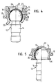
- FIG. 4 shows a second embodiment of a ball joint.
- the same reference numerals are used, and reference is made to the above explanations.
- the ball pin 12 is inserted in the second embodiment, that the connecting bolt 14 protrudes through the single-ended end of the wall 20. This end is suitably bent inwardly, so that the ball head 16 is securely held in the receiving space 18.
- the free end of the wall 20 is provided with a skirt 32, which is bent radially outward. On the skirt 32, a sealing bellows can be attached.
- an internal shoulder 34 is provided in the second embodiment, on which the collar 26 of the lid 28 abuts (see the illustration to the right of the center line).
- FIG. 5 shows an embodiment of a ball joint according to the invention.
- the wall 20 is designed only as a comparatively narrow ring, which does not protrude beyond the ball head 16 in the axial direction.
- a lid 28 is welded on the side of the wall, which is designed in two layers.
- a reinforcing ring 36 is welded on the other side of the wall 20, that is, at the end, which is made in one layer. This prevents even at low wall thickness of the wall 20, that it can not be bent at high loads on the axial ends of the receiving space 18 and the ball pin 12 securely in the receiving space 18 is held.
- the reinforcing ring 36 can be used for secure fixing of a sealing bellows on the ball joint.
Landscapes
- Engineering & Computer Science (AREA)
- General Engineering & Computer Science (AREA)
- Mechanical Engineering (AREA)
- Pivots And Pivotal Connections (AREA)
Abstract
Description
- Die Erfindung betrifft ein Kugelgelenk nach dem Oberbegriff des Anspruchs 1.
- Ein Kugelgelenk mit einem Kugelzapfen, einem von einer Wandung begrenzten Aufnahmeraum für den Kugelzapfen und einem Anschlußbauteil aus Blech, wobei die Wandung des Aufnahmeraumes einstückig mit dem Anschlußbauteil ausgeführt ist, ist aus der japanischen Patentanmeldung mit der Offenlegungsnummer
10-37944 08214384 - Ein Kugelgelenk mit dem Merkmalen des Oberbegriffs des Anspruchs 1 ist in der
FR-A-1 153 763 - Die Aufgabe der Erfindung besteht darin, ein Kugelgelenk der eingangs genannten Art dahingehend weiterzubilden, daß eine größere Variabilität möglich ist.
- Zu diesem Zweck ist gemäß der Erfindung ein Kugelgelenk mit den Merkmalen des Anspruchs 1 vorgesehen. Die erfindungsgemäße Gestaltung ermöglicht, den Kugelzapfen sowohl in der einen als auch in der anderen Richtung aus der Aufnahme herausragen zu lassen. Auch ist es möglich, sehr unterschiedliche Deckel oder Lagerschalen im Inneren des Aufnahmeraumes anzuordnen. Schließlich ergeben sich Vorteile bei der Montage des Kugelzapfens im Aufnahmeraum. Im Stand der Technik nach der
JP-A-10-37944 - Vorteilhafte Ausgestaltungen der Erfindung ergeben sich aus den Unteransprüchen.
- Die Erfindung wird nachfolgend anhand verschiedener Ausführungsformen beschrieben, die in den beigefügten Zeichnungen dargestellt sind. In diesen zeigen:
- Figur 1 ein Anschlußbauteil mit Aufnahmeraum für den Kugelzapfen in einem ersten Zwischenschritt während der Herstellung;
- Figur 2 das Anschlußbauteil von Figur 1 in einem weiteren Zwischenschritt;
- Figur 3 in einer Schnittansicht eine nicht erfindungsgemäße Ausführungsform eines Kugelgelenks, wobei rechts und links der Mittellinie unterschiedliche Varianten gezeigt sind;
- Figur 4 in einer Schnittansicht eine weitere, nicht erfindungsgemäße Ausführungsform eines Kugelgelenks, wobei rechts und links der Mittellinie unterschiedliche Varianten gezeigt sind; und
- Figur 5 in einer Schnittansicht eine erfindungsgemäße Ausführungsform eines Kugelgelenks.
- In Figur 1 ist ein Anschlußbauteil 10 gezeigt, das aus Blech besteht und beispielsweise ein Querlenker eines Radaufhängungssystems für ein Kraftfahrzeug ist. Am Anschlußbauteil 10 soll ein Kugelgelenk vorgesehen sein, das im wesentlichen aus einem Kugelzapfen 12 (siehe Figur 3) mit einem Anschlußbolzen 14 und einem Kugelkopf 16 besteht, der in einem Aufnahmeraum 18 angeordnet ist. Der Aufnahmeraum ist begrenzt von einer Wandung 20, die einstückig mit dem Anschlußbauteil 10 ausgebildet ist. Zu diesem Zweck wird an der Stelle des Anschlußbauteils, an dem das Kugelgelenk anzuordnen ist, zunächst das Material des Anschlußbauteils 10 durch einen Stülpprozeß in eine topf- oder napfähnliche Struktur umgeformt, die sich zu beiden Seiten der Blechebene erstreckt. Dann wird der Boden des so entstandenen Topfes ausgestanzt, so daß eine rohrförmige Wandung 20 erhalten wird. Dieser Zustand ist in Figur 1 gezeigt. Die Wandung 20 definiert den Aufnahmeraum 18, der somit an beiden axialen Enden offen ist. Die Wandung 20 ist in dem Bereich, der oberhalb der vom Blech des Anschlußbauteils 10 definierten Ebene liegt, zweilagig ausgeführt, während der unterhalb dieser Ebene liegende Abschnitt der Wandung 20 einlagig ausgeführt ist.
- Nach dem Ausstanzen des Bodens wird das axiale Ende der Wandung 20, an dem diese zweilagig ausgebildet ist, radial einwärts verformt, so daß die in Figur 2 gezeigte Gestalt der Wandung 20 erhalten wird. Die Wandung kann vergleichsweise problemlos verformt werden, da ein geeigneter Gegenhalter in das Innere des Aufnahmeraumes 18 eingebracht werden kann. Am entgegengesetzten axialen Ende der Wandung 20, also am einlagig ausgeführten Ende, wird die Wandung so verformt, daß ein radialer, umlaufender Absatz 21 gebildet ist. Dieser ist bei der in Figur 3 links der Mittellinie gezeigten Variante als vorstehender Kragen ausgebildet, während er bei der rechts der Mittellinie gezeigten Variante an der Rückseite eines Wulstes gebildet ist. Zusätzlich ist auf der Innenseite des Wulstes eine umlaufende Nut 22 vorgesehen.
- Anschließend wird auf dem Kugelkopf 16 des Kugelzapfens 12 eine Lagerschale 24 montiert, und der Kugelzapfen 12 wird zusammen mit der Lagerschale 24 in den Aufnahmeraum 18 eingesetzt. Die Lagerschale 24 ist an ihrem vom Anschlußbolzen 14 abgewandten Ende mit einem radial vorstehenden Kragen 26 versehen, der bei der in Figur 3 links der Mittellinie gezeigten Variante auf der Stirnseite der Wandung 20 anliegt, während er bei der rechts der Mittellinie gezeigten Variante in die Nut 22 eingreift. Bei beiden Varianten ist die Lagerschale 24 auf diese Weise in axialer Richtung fixiert. Abschließend wird ein Deckel 28 angebracht, der den Aufnahmeraum 18 verschließt, wobei zwischen dem Deckel 28 und der Lagerschale 24 noch eine Druckfeder 30 eingesetzt wird. Der Deckel 28 wird bei der in Figur 3 rechts der Mittellinie gezeigten Variante an der Wandung 20 dadurch befestigt, daß er hinter dem Absatz 21 verstemmt wird. Bei der in Figur 3 links der Mittellinie gezeigten Variante wird der Deckel 28 mit der Wandung verschweißt.
- In Figur 4 ist eine zweite Ausführungsform eines Kugelgelenks gezeigt. Für die von der ersten Ausführungsform bekannten Bauteile werden dieselben Bezugszeichen verwendet, und es wird auf die obigen Erläuterungen verwiesen.
- Im Unterschied zur ersten Ausführungsform ist bei der zweiten Ausführungsform der Kugelzapfen 12 so eingesetzt, daß der Anschlußbolzen 14 durch das einlagig ausgeführte Ende der Wandung 20 hervorsteht. Dieses Ende ist geeignet nach innen gebogen, so daß der Kugelkopf 16 sicher im Aufnahmeraum 18 gehalten ist. Bei der links der Mittellinie gezeigten Variante ist das freie Ende der Wandung 20 mit einer Schürze 32 versehen, die radial nach außen abgebogen ist. An der Schürze 32 kann ein Dichtungsbalg befestigt werden.
- Am anderen axialen Ende der Wandung 20 ist bei der zweiten Ausführungsform ein innenliegender Absatz 34 vorgesehen, an dem der Kragen 26 des Deckels 28 anliegt (siehe die Darstellung rechts der Mittellinie). Nach dem Einsetzen des Deckels 28 wird das axiale Ende der doppellagigen Wandung 20 umgeformt, so daß der Kragen 26 des Deckels 28 nach Art einer Bördelung fest eingeklemmt wird (siehe die Darstellung links der Mittellinie). Das Kugelgelenk ist nun vollständig verschlossen.
- In Figur 5 ist eine erfindungsgemäße Ausführungsform eines Kugelgelenks gezeigt. Im Unterschied zur ersten Ausführungsform ist hier die Wandung 20 nur als vergleichsweise schmaler Ring ausgeführt, der in axialer Richtung nicht über den Kugelkopf 16 hinausragt. Auf der Seite der Wandung, die zweilagig ausgeführt ist, ist ein Deckel 28 aufgeschweißt. Auf der anderen Seite der Wandung 20, also an dem Ende, das einlagig ausgeführt ist, ist ein Verstärkungsring 36 angeschweißt. Dieser verhindert auch bei geringer Wandstärke der Wandung 20, daß diese auch bei hohen Belastungen nicht an den axialen Enden des Aufnahmeraumes 18 aufgebogen werden kann und der Kugelzapfen 12 sicher im Aufnahmeraum 18 gehalten ist. Zusätzlich kann der Verstärkungsring 36 zur sicheren Festlegung eines Dichtungsbalges am Kugelgelenk dienen.
Claims (8)
- Kugelgelenk mit einem Kugelzapfen (12), einem von einer Wandung (20) begrenzten, in axialer Richtung beidseitig offenen Aufnahmeraum (18) für den Kugelzapfen (12) und einem Anschlußbauteil (10) aus Blech, wobei die Wandung (20) des Aufnahmeraumes (18) einstückig mit dem Anschlußbauteil (10) ausgeführt ist, dadurch gekennzeichnet, daß die Wandung (20) des Aufnahmeraumes (18) an beiden axialen Enden radial nach innen gebogen ist, so daß der Kugelzapfen (12) im Aufnahmeraum (18) gehalten ist.
- Kugelgelenk nach Anspruch 1, dadurch gekennzeichnet, daß die Wandung (20) abschnittsweise zweilagig ausgeführt ist.
- Kugelgelenk nach Anspruch 2, dadurch gekennzeichnet, daß die Wandung (20) erhalten ist durch plastisches Verformen derart, daß ein Napf gebildet ist, und anschließendes Ausstanzen des Bodens des Napfes.
- Kugelgelenk nach Anspruch 2 oder Anspruch 3, dadurch gekennzeichnet, daß der Kugelzapfen (12) einen Anschlußbolzen (14) aufweist und der Anschlußbolzen durch das Ende des Aufnahmeraumes (18) nach außen ragt, an dem die Wandung (20) des Aufnahmeraumes (18) einlagig ausgeführt ist.
- Kugelgelenk nach einem der vorhergehenden Ansprüche, dadurch gekennzeichnet, daß ein Deckel (28) vorgesehen ist, der ein axiales Ende der Wandung (20) des Aufnahmeraumes (18) umgreift.
- Kugelgelenk nach Anspruch 5, dadurch gekennzeichnet, daß der Deckel (28) mit der Wandung (20) des Aufnahmeraumes (18) verschweißt ist.
- Kugelgelenk einem der vorhergehenden Ansprüche, dadurch gekennzeichnet, daß ein Ring (36) vorgesehen ist, der die Wandung (20) des Aufnahmeraumes (18) an einem axialen Ende umgreift.
- Kugelgelenk nach Anspruch 7, dadurch gekennzeichnet, daß der Ring (36) mit der Wandung (20) des Aufnahmeraumes (18) verschweißt ist.
Applications Claiming Priority (2)
| Application Number | Priority Date | Filing Date | Title |
|---|---|---|---|
| DE20120251U DE20120251U1 (de) | 2001-12-12 | 2001-12-12 | Kugelgelenk |
| EP02795145A EP1454073B1 (de) | 2001-12-12 | 2002-12-10 | Kugelgelenk |
Related Parent Applications (1)
| Application Number | Title | Priority Date | Filing Date |
|---|---|---|---|
| EP02795145A Division EP1454073B1 (de) | 2001-12-12 | 2002-12-10 | Kugelgelenk |
Publications (2)
| Publication Number | Publication Date |
|---|---|
| EP1760337A2 true EP1760337A2 (de) | 2007-03-07 |
| EP1760337A3 EP1760337A3 (de) | 2007-05-09 |
Family
ID=7965162
Family Applications (3)
| Application Number | Title | Priority Date | Filing Date |
|---|---|---|---|
| EP06008875A Expired - Lifetime EP1681478B1 (de) | 2001-12-12 | 2002-12-10 | Kugelgelenk |
| EP06023453A Withdrawn EP1760337A3 (de) | 2001-12-12 | 2002-12-10 | Kugelgelenk |
| EP02795145A Expired - Lifetime EP1454073B1 (de) | 2001-12-12 | 2002-12-10 | Kugelgelenk |
Family Applications Before (1)
| Application Number | Title | Priority Date | Filing Date |
|---|---|---|---|
| EP06008875A Expired - Lifetime EP1681478B1 (de) | 2001-12-12 | 2002-12-10 | Kugelgelenk |
Family Applications After (1)
| Application Number | Title | Priority Date | Filing Date |
|---|---|---|---|
| EP02795145A Expired - Lifetime EP1454073B1 (de) | 2001-12-12 | 2002-12-10 | Kugelgelenk |
Country Status (6)
| Country | Link |
|---|---|
| EP (3) | EP1681478B1 (de) |
| JP (1) | JP2005515366A (de) |
| AU (1) | AU2002361043A1 (de) |
| DE (3) | DE20120251U1 (de) |
| PL (1) | PL362769A1 (de) |
| WO (1) | WO2003054400A1 (de) |
Cited By (2)
| Publication number | Priority date | Publication date | Assignee | Title |
|---|---|---|---|---|
| WO2013013779A1 (de) * | 2011-07-28 | 2013-01-31 | Trw Automotive Gmbh | Gelenkgehäuse eines kugelgelenks sowie verfahren zur montage des gelenkgehäuses an einem trägerelement |
| US11608854B2 (en) | 2017-08-16 | 2023-03-21 | Multimatic Inc. | Ball joint with injection molded bearing |
Families Citing this family (3)
| Publication number | Priority date | Publication date | Assignee | Title |
|---|---|---|---|---|
| DE10325280A1 (de) * | 2003-06-03 | 2005-01-05 | ZF Lemförder Metallwaren AG | Kugelgelenk und Verfahren zu dessen Herstellung |
| DE102013106707B4 (de) | 2013-06-26 | 2015-03-05 | Benteler Automobiltechnik Gmbh | Verfahren zur Herstellung eines Kraftfahrzeuglenkers mit Kugelgelenk |
| DE102015224616A1 (de) * | 2015-12-08 | 2017-06-08 | Robert Bosch Gmbh | Verfahren zum Befestigen einer Kugelschale in einer Gelenkstange und Gelenkstange mit Kugelschale |
Family Cites Families (16)
| Publication number | Priority date | Publication date | Assignee | Title |
|---|---|---|---|---|
| GB558161A (en) * | 1941-08-21 | 1943-12-23 | Leon Thiry | Improvements in or relating to ball and socket type joints |
| US2910316A (en) * | 1955-07-21 | 1959-10-27 | Thompson Ramo Wooldridge Inc | Stamped socket assembly |
| FR1153763A (fr) * | 1955-07-21 | 1958-03-21 | Thompson Prod Inc | Joint à rotule en tôle estampée |
| DE1266060B (de) * | 1962-09-27 | 1968-04-11 | Ehrenreich & Cie A | Verfahren zum Herstellen einer Ringwulst fuer das Befestigen eines Dichtungsbalges an einem Kugelgelenkgehaeuse |
| NL6715396A (de) * | 1967-11-14 | 1969-05-19 | ||
| US3613201A (en) * | 1970-01-20 | 1971-10-19 | Trw Inc | Stamped ball joint assembly and method of making same |
| GB1363661A (en) * | 1972-08-11 | 1974-08-14 | Ada Halifax Ltd | Bearings for motors |
| DE2420241A1 (de) * | 1974-04-26 | 1975-11-06 | Bosch Gmbh Robert | Antriebsgestaengeteil |
| GR64390B (en) * | 1976-05-29 | 1980-03-21 | Ehrenreich Gmbh & Co Kg A | Method for the construction of a ball and socket joint |
| JPS5382957A (en) * | 1976-12-29 | 1978-07-21 | Tokai Trw & Co | Method of fastening ball joint |
| DE3018187A1 (de) * | 1980-05-13 | 1981-11-19 | Daimler-Benz Ag, 7000 Stuttgart | Kugelgelenk und verfahren zu dessen herstellung |
| US5061110A (en) * | 1991-02-08 | 1991-10-29 | Trw Inc. | Ball joint and method of assembly |
| JP3168229B2 (ja) | 1992-10-06 | 2001-05-21 | 日本発条株式会社 | ボールジョイント装置 |
| DE4301303C1 (de) * | 1993-01-20 | 1994-08-18 | Lemfoerder Metallwaren Ag | Kugelgelenk |
| JPH1037944A (ja) * | 1996-07-24 | 1998-02-13 | Otix:Kk | ボールジョイント構造体 |
| DE19952472C5 (de) | 1999-11-03 | 2010-07-08 | ZF Lemförder GmbH | Kugelgelenk |
-
2001
- 2001-12-12 DE DE20120251U patent/DE20120251U1/de not_active Expired - Lifetime
-
2002
- 2002-12-10 DE DE50213250T patent/DE50213250D1/de not_active Expired - Lifetime
- 2002-12-10 PL PL02362769A patent/PL362769A1/xx unknown
- 2002-12-10 EP EP06008875A patent/EP1681478B1/de not_active Expired - Lifetime
- 2002-12-10 AU AU2002361043A patent/AU2002361043A1/en not_active Abandoned
- 2002-12-10 EP EP06023453A patent/EP1760337A3/de not_active Withdrawn
- 2002-12-10 DE DE50209386T patent/DE50209386D1/de not_active Expired - Fee Related
- 2002-12-10 JP JP2003555084A patent/JP2005515366A/ja active Pending
- 2002-12-10 EP EP02795145A patent/EP1454073B1/de not_active Expired - Lifetime
- 2002-12-10 WO PCT/EP2002/014016 patent/WO2003054400A1/de not_active Ceased
Cited By (7)
| Publication number | Priority date | Publication date | Assignee | Title |
|---|---|---|---|---|
| WO2013013779A1 (de) * | 2011-07-28 | 2013-01-31 | Trw Automotive Gmbh | Gelenkgehäuse eines kugelgelenks sowie verfahren zur montage des gelenkgehäuses an einem trägerelement |
| CN103782046A (zh) * | 2011-07-28 | 2014-05-07 | Trw汽车股份有限公司 | 球窝关节的关节壳体以及用于将关节壳体装配在支架元件上的方法 |
| CN103782046B (zh) * | 2011-07-28 | 2016-08-17 | Trw汽车股份有限公司 | 球窝关节的关节壳体以及用于将关节壳体装配在支架元件上的方法 |
| US9429186B2 (en) | 2011-07-28 | 2016-08-30 | THK RHYTHM AUTOMOTIVE GmbH | Joint housing of a ball joint as well as method for mounting the joint housing on a carrier element |
| US10087983B2 (en) | 2011-07-28 | 2018-10-02 | THK RHYTIIM AUTOMOTIVE GmbH | Joint housing of a ball joint as well as method for mounting the joint housing on a carrier element |
| US11608854B2 (en) | 2017-08-16 | 2023-03-21 | Multimatic Inc. | Ball joint with injection molded bearing |
| US11649852B2 (en) | 2017-08-16 | 2023-05-16 | Multimatic Inc. | Ball joint with injection molded bearing |
Also Published As
| Publication number | Publication date |
|---|---|
| DE20120251U1 (de) | 2002-04-18 |
| JP2005515366A (ja) | 2005-05-26 |
| EP1760337A3 (de) | 2007-05-09 |
| EP1681478B1 (de) | 2009-01-21 |
| AU2002361043A1 (en) | 2003-07-09 |
| PL362769A1 (en) | 2004-11-02 |
| EP1454073B1 (de) | 2007-01-24 |
| WO2003054400A1 (de) | 2003-07-03 |
| EP1681478A2 (de) | 2006-07-19 |
| DE50209386D1 (de) | 2007-03-15 |
| EP1454073A1 (de) | 2004-09-08 |
| DE50213250D1 (de) | 2009-03-12 |
| EP1681478A3 (de) | 2006-08-16 |
Similar Documents
| Publication | Publication Date | Title |
|---|---|---|
| EP2639464B1 (de) | Kugelgelenk mit Balgdichtung | |
| DE19542071C2 (de) | Kugelgelenk | |
| WO2008055454A1 (de) | Kugelgelenk | |
| DE19630130C2 (de) | Endstück für den Einfüllstutzen eines Kraftfahrzeug-Kraftstofftankes | |
| EP2737224B1 (de) | Gelenkgehäuse eines kugelgelenks sowie verfahren zur montage des gelenkgehäuses an einem trägerelement | |
| DE19755020B4 (de) | Axialgelenk | |
| DE19622700A1 (de) | Zusammengesetztes und mit Gehäuse umgebenes Kugelgelenk | |
| DE112019003571T5 (de) | Kugelpfannenbaugruppe mit gepresster abdeckplatte und verfahren zu ihrer herstellung | |
| EP0155485B1 (de) | Axialkugelgelenk für Gelenkgestänge in Kraftfahrzeugen | |
| EP1432920B1 (de) | Kugelgelenk | |
| EP0924441A1 (de) | Kugelgelenk und Verfahren zu seiner Vorspannung | |
| DE112019001179T5 (de) | Verbesserte Buchsenbaugruppe und Herstellungsverfahren | |
| EP1681478B1 (de) | Kugelgelenk | |
| DE102018215172B4 (de) | Kugelgelenk für ein Fahrzeug sowie Verschlusselement für ein solches Kugelgelenk | |
| DE102009031738B4 (de) | Kugelgelenk | |
| EP3054182B1 (de) | Verfahren zur herstellung einer fügeverbindung zwischen einem gelenkgehäuse und einem anbindungsbauteil, sowie verfahrensgemäss hergestelltes fahrwerkbauteil | |
| DE102004061057B4 (de) | Kugelgelenkverbindung zwischen einem Zapfen und einem Befestigungsteil | |
| EP1446587B1 (de) | Gelenk | |
| EP0751310B1 (de) | Kugelgelenk | |
| EP3642060B1 (de) | Verfahren zur herstellung eines fahrzeugbauteils und fahrzeugbauteil hergestellt nach diesem verfahren | |
| DE202010000258U1 (de) | Kugelgelenk, insbesondere für ein Fahrwerk eines Kraftfahrzeuges | |
| DE69103184T2 (de) | Verschlusskappe eines schlauchförmigen Organs, insbesondere für ein teleskopisches System von Kardanantriebswellen. | |
| DE102006061974A1 (de) | Kugelgelenk mit Verschlussring | |
| DE4412597C2 (de) | Kugelgelenk für Fahrwerksteile in einem Kraftfahrzeug | |
| EP0311810B1 (de) | Demontierbares Kugelgelenk mit Deckeldichtung für Kraftfahrzeuge |
Legal Events
| Date | Code | Title | Description |
|---|---|---|---|
| PUAI | Public reference made under article 153(3) epc to a published international application that has entered the european phase |
Free format text: ORIGINAL CODE: 0009012 |
|
| AC | Divisional application: reference to earlier application |
Ref document number: 1454073 Country of ref document: EP Kind code of ref document: P |
|
| AK | Designated contracting states |
Kind code of ref document: A2 Designated state(s): DE FR GB IT |
|
| PUAL | Search report despatched |
Free format text: ORIGINAL CODE: 0009013 |
|
| AK | Designated contracting states |
Kind code of ref document: A3 Designated state(s): DE FR GB IT |
|
| 17P | Request for examination filed |
Effective date: 20071011 |
|
| 17Q | First examination report despatched |
Effective date: 20071107 |
|
| AKX | Designation fees paid |
Designated state(s): DE FR GB IT |
|
| STAA | Information on the status of an ep patent application or granted ep patent |
Free format text: STATUS: THE APPLICATION IS DEEMED TO BE WITHDRAWN |
|
| 18D | Application deemed to be withdrawn |
Effective date: 20080518 |