EP1760904A1 - Verfahren und Vorrichtung zum Messen des Nebensprechens - Google Patents
Verfahren und Vorrichtung zum Messen des Nebensprechens Download PDFInfo
- Publication number
- EP1760904A1 EP1760904A1 EP05291798A EP05291798A EP1760904A1 EP 1760904 A1 EP1760904 A1 EP 1760904A1 EP 05291798 A EP05291798 A EP 05291798A EP 05291798 A EP05291798 A EP 05291798A EP 1760904 A1 EP1760904 A1 EP 1760904A1
- Authority
- EP
- European Patent Office
- Prior art keywords
- crosstalk
- transmission
- transmission line
- uic
- identification code
- Prior art date
- Legal status (The legal status is an assumption and is not a legal conclusion. Google has not performed a legal analysis and makes no representation as to the accuracy of the status listed.)
- Granted
Links
- 238000000034 method Methods 0.000 title claims abstract description 34
- 230000005540 biological transmission Effects 0.000 claims abstract description 132
- 230000008878 coupling Effects 0.000 claims abstract description 35
- 238000010168 coupling process Methods 0.000 claims abstract description 35
- 238000005859 coupling reaction Methods 0.000 claims abstract description 35
- 238000012360 testing method Methods 0.000 claims abstract description 28
- 238000001228 spectrum Methods 0.000 claims description 16
- 238000004590 computer program Methods 0.000 claims description 5
- 238000012544 monitoring process Methods 0.000 claims description 4
- 230000003595 spectral effect Effects 0.000 claims description 4
- 230000010354 integration Effects 0.000 claims description 3
- 230000003213 activating effect Effects 0.000 claims description 2
- 238000005516 engineering process Methods 0.000 claims 1
- 239000011230 binding agent Substances 0.000 description 9
- 238000013459 approach Methods 0.000 description 5
- 239000003795 chemical substances by application Substances 0.000 description 5
- 238000010586 diagram Methods 0.000 description 5
- 230000008859 change Effects 0.000 description 4
- 230000007423 decrease Effects 0.000 description 3
- 238000013461 design Methods 0.000 description 2
- 238000001514 detection method Methods 0.000 description 2
- 230000008569 process Effects 0.000 description 2
- 238000011144 upstream manufacturing Methods 0.000 description 2
- 101150012579 ADSL gene Proteins 0.000 description 1
- 102100020775 Adenylosuccinate lyase Human genes 0.000 description 1
- 108700040193 Adenylosuccinate lyases Proteins 0.000 description 1
- RYGMFSIKBFXOCR-UHFFFAOYSA-N Copper Chemical compound [Cu] RYGMFSIKBFXOCR-UHFFFAOYSA-N 0.000 description 1
- 230000000295 complement effect Effects 0.000 description 1
- 238000010276 construction Methods 0.000 description 1
- 229910052802 copper Inorganic materials 0.000 description 1
- 239000010949 copper Substances 0.000 description 1
- 238000003745 diagnosis Methods 0.000 description 1
- 230000009977 dual effect Effects 0.000 description 1
- 230000000694 effects Effects 0.000 description 1
- 230000000763 evoking effect Effects 0.000 description 1
- 239000000796 flavoring agent Substances 0.000 description 1
- 235000019634 flavors Nutrition 0.000 description 1
- 238000003780 insertion Methods 0.000 description 1
- 230000037431 insertion Effects 0.000 description 1
- 230000000873 masking effect Effects 0.000 description 1
- 230000007246 mechanism Effects 0.000 description 1
- 230000000116 mitigating effect Effects 0.000 description 1
- 230000009467 reduction Effects 0.000 description 1
- 230000008054 signal transmission Effects 0.000 description 1
- 230000003068 static effect Effects 0.000 description 1
- 230000001131 transforming effect Effects 0.000 description 1
Images
Classifications
-
- H—ELECTRICITY
- H04—ELECTRIC COMMUNICATION TECHNIQUE
- H04B—TRANSMISSION
- H04B3/00—Line transmission systems
- H04B3/02—Details
- H04B3/46—Monitoring; Testing
- H04B3/487—Testing crosstalk effects
Definitions
- the invention relates to a method for determining crosstalk coupling between a plurality of transmission lines in digital data transmission systems, in particular DSL networks.
- the invention also relates to a crosstalk determining unit for integration in or for connection to an access node of a digital data transmission system, in particular a DSL network, with a plurality of transmission lines coupled to the access node.
- the invention relates to a digital data transmission system, in particular in the form of a DSL network, and to a computer program product for determining crosstalk coupling in digital data transmission systems, in particular DSL networks, with a plurality of transmission lines.
- Crosstalk remains one of the major limiting factors for Digital Subscriber Lines (DSL) transmission, as it effectively limits the obtainable DSL bitrate (for a given loop length) or the DSL reach at a guaranteed minimum bitrate. Furthermore, crosstalk can cause errors in transmission, service interruption, and the need for time consuming re-initializations and re-synchronizations. As a consequence crosstalk plays a major role in DSL service deployment. Additionally, knowledge of crosstalk coupling is equally valuable for other DSL deployment scenarios, e.g. service upgrading, fault diagnosis, etc. For all DSL deployment phases (such as prequalification or in-service optimisation), solutions are needed that help to estimate the impact of crosstalk, or even to minimise it (such as dynamic spectrum management DSM).
- DSM dynamic spectrum management
- FEXT far-end crosstalk
- NEXT near-end crosstalk
- lines transmission lines
- DSL Digital Subscriber Line Access Multiplexer
- Crosstalk coupling is present between all line couples, but the crosstalk coupling is not equally strong for each line couple.
- lines inside a cable are grouped in binders, crosstalk coupling between lines in the same binder is on average higher than crosstalk between lines in separate binders.
- an important point is to know which lines are contained in one binder.
- a first kind of prior art solutions for determining crosstalk levels rely on worst-case assumptions: Since the crosstalk coupling functions and the users that share the same binder are generally unknown, DSM algorithms have to resort to worst case crosstalk coupling functions, which are often overly conservative.
- An alternative prior art approach as described in European patent application 04 292 070.2 incorporated herein by reference includes Virtual Binder Identification through polling: This technique allows to detect which lines generate the highest amount of crosstalk towards a given transmission line of interest. It consists in continuously monitoring the on/off status and/or the noise margin of modems on different transmission lines.
- the first modem/line can be identified as a dominant crosstalker with respect to the second modem/line.
- a crosstalk coupling constant can be estimated.
- a DSLAM can only process a small number of simple network management protocol (SNMP) commands per minute, which limits the number of lines that can be monitored at a given time.
- SNMP simple network management protocol
- Still another disadvantage concerns the uniqueness of the polling result: If two modems ("disturbers") switch on at essentially the same time, and two other modems (“victims”) have to retrain or find their noise margin reduced as a result of this, it is impossible to determine which victim is affected by which disturber. Hence, the polling process of crosstalk detection is not unique, which may lead to incorrect spectrum management.
- the object is achieved by means of a method for determining crosstalk coupling between a plurality of transmission lines in digital data transmission systems, in particular DSL networks, comprising the steps of: generating at least one test signal having a unique identification code in the frequency domain, said code being associated with a first transmission line; sending the test signal on the first transmission line; monitoring at least a second transmission line for detecting a crosstalk signal; and determining whether the crosstalk signal is caused by the test signal of the first transmission line by means of a signature of the unique identification code comprised in the crosstalk signal.
- a crosstalk coupling determining unit for integration in or for connection to an access node of a digital data transmission system, in particular a DSL network, with a plurality of transmission lines coupled to the access node, comprising: unique identification code generating means for generating at least one unique identification code in the frequency domain, said code being associated with a first transmission line; means for providing the unique identification code to a management information database of the access node; information gathering means for gathering quantitative information indicative of crosstalk coupling from the management information database; and determination means for determining crosstalk coupling between the second transmission line and the first transmission line by means of a signature of the unique identification code comprised in said quantitative information.
- a digital data transmission system in particular in the form of a DSL network, comprising: an access node comprising a management information database including quantitative information indicative of a crosstalk coupling between any two of the transmission lines; a plurality of modems connected to the access node via transmission lines by means of conducting wire, where the access node is located in a central office (CO-fed) and/or in a remote terminal (RT-fed), and an inventive crosstalk coupling determining unit.
- CO-fed central office
- RT-fed remote terminal
- the object is achieved by means of a computer program product for determining crosstalk in digital data transmission systems, in particular DSL networks, with a plurality of transmission lines, being operable to perform the inventive method.
- the basic idea of the invention consists in uniquely determining which lines are mutually coupling by sending a dedicated test signal having a unique identification code (e.g. identification tones).
- a unique identification code e.g. identification tones
- the crosstalk effect evoked by such a test signal is quite simple to monitor, such that no polling mechanism is required to detect when modems are switched on or off.
- the inventive approach is highly scalable, therefore monitoring of thousands of lines is possible at a reduced overall system complexity.
- identification codes one can uniquely identify the disturber, e.g. an RT modem.
- two RT-fed lines at distinct RT disturbers switch on at the same time and two victims, e.g. CO-fed modems, fail simultanously, it would be impossible to determine which CO-line was affected by which RT-line/modem.
- the test signal is added to the power spectral density (PSD) of a normal transmission signal (transmit PSD) of the line under test.
- PSD power spectral density
- transmit PSD normal transmission signal
- the crosstalk determining unit plays the role of a central agent, which is able to monitor thousands of DSL lines by means of SNMP commands and by using quantitative information gathered from a management information database (MIB) comprised in said access node (DSLAM).
- MIB management information database
- DSLAM access node
- generation of the test signal comprises activating a number of tones located at predetermined frequencies within a transmission frequency spectrum, which are not being used for a normal transmission signal, wherein the number and/or location of the tones constitutes the unique identification code.
- a small number of tones could advantageously be activated at the low frequencies of the transmission frequency spectrum.
- the positions and/or the number of these additional tones are chosen to be unique and determine a particular code. CO-connected users, which often experience major crosstalk from RT-connected users, can then be monitored by using corresponding quantitative information available in the MIB.
- said quantitative information comprises at least one of bit loading and noise level on the second transmission line
- the determination means of the inventive crosstalk determining unit are adapted for determining the crosstalk coupling between the second transmission line and the first transmission line by detecting a signature of the unique identification code correspondingly in at least one of bit loading and quiet line noise (QLN) on the second transmission line. If the bit loading drops at the positions of the identification tones (or the noise increases at said positions), the central agent will know that the CO-fed user is a victim of that particular RT, which is uniquely identified by its associated test signal coding. Assigning unique codes to different modems, e.g. RTs, thus allows to perform the aforementioned procedure in parallel over multiple RTs, since they can be accurately distinguished due to their particular code.
- generation of the test signal comprises deactivating a number of tones located at predetermined frequencies within a transmission frequency spectrum, wherein the number and/or location of the tones constitutes the unique identification code.
- This approach is complementary to the aforementioned technique: If an RT-deployed modem is using the entire transmission frequency band, it will preferably switch off a number of tones in order to incorporate coding information in its normal transmission signal. Again, the positions of the (deactivated) tones determine the code. An increase in bitrate or a decrease in quiet line noise would be detectable at the victim modems.
- test signal comprises switching off all tones located on one side of a transmission frequency spectrum with respect to a dividing frequency and switching on all tones located on the other side of the transmission frequency spectrum with respect to the dividing frequency.
- position of said dividing frequency or "split tone" serves as a unique code.
- the inventive method comprises the further step of grouping the transmission lines which show crosstalk coupling to the first transmission line into a virtual binder of the first transmission line.
- the method according to the invention can be used to determine which lines affect one another by crosstalk.
- the presented technique also allows to measure the magnitude (strength) of the crosstalk over frequency, e.g. by taking into account the quantitative reduction in bit loading or the quantitative increase in quiet line noise (QLN) at a particular frequency, which is a property similar to virtual binder identification through polling (cf. prior art).
- virtual binder identification through polling is a technique that exploits time domain information, i.e. detecting a change in status from on to off at a particular moment in time for disturber modems and the associated drop in noise margin for the victim modems.
- the inventive method exploits information in the frequency domain, and therefore is not time critical. While polling all lines simultaneously is not feasible in practise, the idea of sending coded PSDs on the other hand achieves a low complexity implementation in current DSL networks.
- the inventive method being complemented by additionally determining the crosstalk between the first transmission line and at least one second transmission line by means of detecting a change in on/off status for a modem associated with the first transmission line and detecting a corresponding change in on/off status and/or noise margin for a modem associated with the second transmission line.
- crosstalk determination can become even more accurate, e.g. in a case where the insertion of an identification code in the frequency domain causes a victim modem to retrain. If this retrain is observed, it is clear that the modem was subjected to crosstalk from the disturber.
- the inventive method as described above is applicable to all ADSL and VDSL flavours. Furthermore, the technique is standard compliant and falls within the constraints imposed by the MIB and the DSLAM.
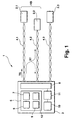
- Fig. 1 shows a digital data transmission system in the form of a DSL access network 1 wherein several hundreds or thousands of DSL modems 2.1-2.3 are connected to an access multiplexer DSLAM 3, also referred to as a DSL central office (CO). To illustrate the working principle of the present invention, only three of those modems 2.1-2.3 are depicted for reasons of clarity.
- the modems 2.1-2.3 are coupled to the DSLAM 3 by means of twisted pair copper transmission lines 4.1-4.3. These lines 4.1-4.3 can form part of the same physical binder or can be comprised in different physical binders, which is not shown in Fig. 1. Alternatively, a number of said modems 2.1-2.3 could be RT-deployed modems coupled to a remotely deployed DSLAM.
- the access multiplexer DSLAM 3 in Fig. 1 incorporates a crosstalk determining unit 5 according to the current invention.
- a crosstalk determining unit 5 it is possible to locate the crosstalk determining unit outside of the DSLAM 3, e.g. in a network analyzer.
- the crosstalk determining unit 5 comprises unique identification code generation means 6 for generating at least one unique identification code UIC.
- the crosstalk determining unit 5 further comprises means 7 for providing the UIC to a management information database (MIB) 10 of the DSLAM 3.
- MIB management information database
- the UIC is embedded in the carrier mask, which is a parameter in the MIB 10 to configure transmission lines.
- the crosstalk determining unit 5 defines the carrier mask and writes it to the MIB 10.
- This carrier masking can be set in down- and/or in upstream, e.g. by providing the carrier masks to the corresponding modems 2.1 to 2.3 by using a sending means 8 incorporated in the DSLAM 3. In this way, the carrier mask can also contain a normal transmit signal as well.
- the crosstalk determining unit 5 is used in upstream and consequently, the first modem 2.1 generates and sends a test signal TS on the first transmission line 4.1 (when alternatively using the crosstalk determining unit 5 in downstream, it is the DSLAM 3 that generates and sends the test signal TS).
- the test signal TS has an unique identification code UIC in the frequency domain (cf. Fig. 2), said code being associated with the transmission line 4.1, hereinafter referred to as "first transmission line” 4.1.
- the modem 2.1 sends the test signal possibly together with a normal transmission signal NTS (cf. Fig. 2a).
- the crosstalk coupling determining unit 5 comprises information gathering means 9 for gathering quantitative information indicative of a crosstalk coupling XT between the first transmission line 4.1 and at least one other of the transmission lines, hereinafter referred to as "second transmission line” 4.2.
- the information gathering means 9 are in operative connection with the management information database MIB 10 which includes quantitative information indicative of crosstalk coupling XT between any two of the transmission lines 4.1-4.3, e.g. quiet line noise and bit loading values (cf. Fig. 2), measured on the transmission lines by means of appropriate measuring means 11 also comprised in the access multiplexer DSLAM 3, so that victim lines connected to the same or to another DSLAM writes their impacted bit loading and/or quiet line noise into the MIB 10.
- the crosstalk determining unit 5 futher comprises determination means 12 for determining the crosstalk coupling between the first transmission line 4.1 and the second transmission line 4.2 by means of a signature of the unique identification code UIC comprised in said quantitative information.
- At least the crosstalk coupling determining unit 5 is devised in software form and translated into practise by means of a corresponding computer program product as claimed, which is operable in connection with a suitable program execution means, e.g. a microprocessor with associated strorage means (not shown), comprised in the access multiplexer DSLAM 3.
- a suitable program execution means e.g. a microprocessor with associated strorage means (not shown), comprised in the access multiplexer DSLAM 3.
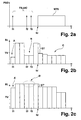
- Fig. 2a is a diagram indicating a transmission signal strength (power spectral density PSD, in arbitrary units) on line 4.1 (Fig. 1) as a function of a transmission frequency f for transmission of a normal transmission signal NTS at higher frequencies with an added unique identification code UIC at lower frequencies in the frequency domain, e.g. in the case of an RT-deployed modem which is normally transmitting at the highest frequencies of the transmission frequency spectrum only.
- Said code UIC is uniquely associated with said first transmission line 4.1 and therefore comprises a unique combination of identification tones IT1-IT3, i.e. signal components at corresponding frequencies f1-f3 as illustrated by means of the vertical arrows in Fig.
- Fig. 2b is a diagram indicating the bit loading BL (in number of bits per subcarrier) on transmission line 4.2 (Fig. 1) as a function of frequency f.
- B bits have been lost at frequency positions that correspond to the identification tones IT1-IT3 sent on the first line 4.1 (cf. Fig. 2a).
- the loss of bits at or around a particular frequency is detected by comparison of the corresponding bit loading value BL with a predetermined threshold value TV .
- a particular frequency e.g. f1
- an increase in quite line noise at frequencies f1-f3 could be measured in the case in which no transmission occurs on the second line 4.2, wherein a rise of said noise value above a corresponding threshold value TV would be indicative of crosstalk affection.
- the crosstalk determining unit 5 is able to determine the disturber modem 2.1/line 4.1 which is crosstalk affecting said line 4.2 by means of its unique identification code UIC, which has left a "bit-loss signature" in the bit loading spectrum of said line 4.2.
- UIC unique identification code
- the decrease in bit loading with respect to an undisturbed line 4.2 which is present in an area marked C in Fig. 2b and which is also due to crosstalk from the first line 4.1, would not be sufficient to detect the disturber-victim relation between the first and second lines 4.1, 4.2 in the frequency domain and in a unique way.
- this information - together with the simultanously occuring bit loading decreases in areas A, B - can be used in the time domain to additionally determine said disturber-victim relation, as disclosed in European patent application 04 292 070.2 .
- Fig. 2c is a diagram indicating the bit loading BL (in number of bits per subcarrier) on the third transmission line 4.3 (Fig. 1) as a function of frequency f.
- bit loading BL in number of bits per subcarrier
- Fig. 1 In areas marked A', B' which correspond to the areas marked A, B in Fig. 2b, no bits have been lost at frequency positions corresponding to the identification tones IT1-IT3 sent on the first line 4.1 (cf. Fig. 2a). Therefore, the third line 4.3 is found to be essentially unaffected by crosstalk from the first line 4.1.
- the identification tones thus reveal by their signature left in quantitative information data of said second line 4.2 that it belongs to a virtual binder VB (Fig. 1) of the first line 4.1, whereas the third line 4.3 does not. It is therefore possible to group the transmission lines 4.1 to 4.3 of the system 1 into virtual binders each of which contains only transmission lines with a high crosstalk correlation among themselves and with a low crosstalk correlation to the transmission lines of the other virtual binders. The distinction between high and low crosstalk correlations is done by using the threshold value as described above.
- the identification tones IT1-IT3 in Fig. 2a preferably correspond to signal gaps rather than signal peaks at certain predetermined frequencies f1-f3.
- the associated code would translate into corresponding bit loading values which lie above the threshold value TV as indicated in Fig. 2b, while all other bit loading values, i.e. at frequencies f ⁇ f1, f2, f3, would be potentially affected and thus lie below said threshold value TV.
- a dividing frequency fd (cf. Figs 2a-c) or split tone can serve as a unique identification code UIC in scenarios in which no dedicated identification tones IT1-IT3 are sent on the first transmission line 4.1.
- Said dividing frequency fd corresponds to a (lower) limiting frequency for normal transmission on said first transmission line 4.1.
- Its signature can be detected on an affected transmission line, i.e. the second transmission line 4.2, if a corresponding step ST in bit loading (cf. Fig. 2b) is greater than another corresponding threshold value.
- a corresponding step ST' is too small in Fig. 2c, again no crosstalk would be detected for transmission lines 4.1 and 4.3.
- inventive method, unit, and system described above can adapt dynamically to a changing user/transmission environment, while obtaining unique crosstalk coupling determination results at all times.
Landscapes
- Engineering & Computer Science (AREA)
- Computer Networks & Wireless Communication (AREA)
- Signal Processing (AREA)
- Cable Transmission Systems, Equalization Of Radio And Reduction Of Echo (AREA)
- Digital Transmission Methods That Use Modulated Carrier Waves (AREA)
- Monitoring And Testing Of Transmission In General (AREA)
- Testing, Inspecting, Measuring Of Stereoscopic Televisions And Televisions (AREA)
Priority Applications (4)
| Application Number | Priority Date | Filing Date | Title |
|---|---|---|---|
| AT05291798T ATE529952T1 (de) | 2005-08-29 | 2005-08-29 | Verfahren und vorrichtung zum messen des nebensprechens |
| EP05291798A EP1760904B1 (de) | 2005-08-29 | 2005-08-29 | Verfahren und Vorrichtung zum Messen des Nebensprechens |
| CN2006101159881A CN1937433B (zh) | 2005-08-29 | 2006-08-22 | 确定串扰耦合的方法和串扰确定单元 |
| US11/510,828 US7702008B2 (en) | 2005-08-29 | 2006-08-28 | Method for determing crosstalk coupling and crosstalk determining unit for integration in digital data transmission systems |
Applications Claiming Priority (1)
| Application Number | Priority Date | Filing Date | Title |
|---|---|---|---|
| EP05291798A EP1760904B1 (de) | 2005-08-29 | 2005-08-29 | Verfahren und Vorrichtung zum Messen des Nebensprechens |
Publications (2)
| Publication Number | Publication Date |
|---|---|
| EP1760904A1 true EP1760904A1 (de) | 2007-03-07 |
| EP1760904B1 EP1760904B1 (de) | 2011-10-19 |
Family
ID=35500871
Family Applications (1)
| Application Number | Title | Priority Date | Filing Date |
|---|---|---|---|
| EP05291798A Expired - Lifetime EP1760904B1 (de) | 2005-08-29 | 2005-08-29 | Verfahren und Vorrichtung zum Messen des Nebensprechens |
Country Status (4)
| Country | Link |
|---|---|
| US (1) | US7702008B2 (de) |
| EP (1) | EP1760904B1 (de) |
| CN (1) | CN1937433B (de) |
| AT (1) | ATE529952T1 (de) |
Cited By (2)
| Publication number | Priority date | Publication date | Assignee | Title |
|---|---|---|---|---|
| EP2117129A1 (de) | 2008-05-07 | 2009-11-11 | Alcatel Lucent | Zugangsnetzwerküberwachungsvorrichtung und -verfahren |
| US7843800B2 (en) * | 2005-09-16 | 2010-11-30 | Huawei Technologies Co., Ltd. | Method, apparatus and system for crosstalk test on multi-subscriber communication lines |
Families Citing this family (27)
| Publication number | Priority date | Publication date | Assignee | Title |
|---|---|---|---|---|
| US20140369480A1 (en) * | 2013-06-12 | 2014-12-18 | Adaptive Spectrum And Signal Alignment, Inc. | Systems, methods, and apparatuses for implementing a dsl system |
| EP2137852A4 (de) * | 2007-04-10 | 2016-02-24 | Ikanos Communications Inc | Verfahren und vorrichtung zur übersprechschätzung |
| EP1998466A1 (de) * | 2007-05-29 | 2008-12-03 | Nokia Siemens Networks Oy | Verfahren und Vorrichtung zur Verarbeitung von Daten und Kommunikationssystem mit einer derartigen Vorrichtung |
| US7843949B2 (en) * | 2007-08-17 | 2010-11-30 | Lantiq Deutschland Gmbh | Communication apparatus and method with changing composition of a vectored group |
| EP2034622A1 (de) * | 2007-09-10 | 2009-03-11 | Alcatel Lucent | Vorrichtung und entsprechendes Verfahren zur Messung von Nebensprechen |
| EP2046004A1 (de) * | 2007-10-03 | 2009-04-08 | Alcatel Lucent | Verfahren und Vorrichtung zur Übersprechungsbeurteilung |
| US9287928B2 (en) * | 2008-04-24 | 2016-03-15 | Lantiq Deutschland Gmbh | Method and apparatus for adding a communication connection to a vectored group |
| EP2301163B1 (de) * | 2008-07-02 | 2018-08-08 | Rambus Inc. | Kapazitiv gekoppelte übersprechunterdrückung |
| US8275054B2 (en) * | 2008-08-21 | 2012-09-25 | Lantiq Deutschland Gmbh | Methods and apparatuses for data transmission |
| US7860023B2 (en) * | 2008-10-21 | 2010-12-28 | At&T Intellectual Property I, L.P. | Layer 2 network rule-based non-intrusive testing verification methodology |
| FR2943476B1 (fr) * | 2009-03-18 | 2011-04-15 | Sagem Comm | Procede et un dispositif de reduction des interferences entre un signal courant porteur et un signal de type vdsl |
| CN101908909B (zh) * | 2009-06-05 | 2013-08-14 | 华为技术有限公司 | 估计远端串扰信道的方法和装置 |
| US20110007623A1 (en) * | 2009-07-10 | 2011-01-13 | Futurewei Technologies, Inc. | Method for Estimating the Strength of a Crosstalk Channel |
| GB2480830B (en) * | 2010-06-01 | 2017-03-22 | Cable Sense Ltd | Signal processing apparatuses and methods |
| RU2585659C2 (ru) * | 2011-01-14 | 2016-06-10 | Телефонактиеболагет Л М Эрикссон (Пабл) | Ограничение перекрестных помех между модемами |
| CN102326334B (zh) * | 2011-08-10 | 2014-03-05 | 华为技术有限公司 | 用于分析线路的串扰的方法及装置 |
| US10205483B2 (en) * | 2014-03-03 | 2019-02-12 | Lantiq Beteiligungs-GmbH & Co. KG | Line simulator |
| US9473240B2 (en) * | 2014-03-14 | 2016-10-18 | Futurewei Technologies, Inc. | Method and apparatus for providing twisted pair multilink communications |
| EP3291491B1 (de) | 2015-05-15 | 2020-01-08 | Huawei Technologies Co., Ltd. | Signalverarbeitungsverfahren und -vorrichtung |
| WO2017190252A1 (en) * | 2016-05-06 | 2017-11-09 | Genesis Technical Systems Corp. | Near-end crosstalk cancellation |
| US10135490B2 (en) * | 2017-04-10 | 2018-11-20 | Cisco Technology, Inc. | Interference group discovery for full duplex network architecture in cable network environment |
| CN107179536A (zh) * | 2017-05-08 | 2017-09-19 | 德越达轨道交通技术(上海)有限公司 | 一种减少雷达测速传感器间串扰的方法 |
| DE102017113413B4 (de) * | 2017-06-19 | 2019-11-14 | Lisa Dräxlmaier GmbH | Vorrichtung, verfahren, herstellverfahren |
| CN108398628B (zh) * | 2018-03-05 | 2021-01-08 | 中国科学院苏州生物医学工程技术研究所 | 一种基于频域特征的高速adc电路板的串扰测量分析方法 |
| TWI764296B (zh) * | 2020-09-25 | 2022-05-11 | 財團法人工業技術研究院 | 用於訊號干擾補償的電子裝置和方法 |
| CN115291089B (zh) * | 2022-10-08 | 2023-08-08 | 本源量子计算科技(合肥)股份有限公司 | 一种串扰测试组件和串扰测试方法 |
| GB2635170A (en) * | 2023-10-31 | 2025-05-07 | Tyco Fire & Security Gmbh | Fire Alarm System Testing |
Citations (3)
| Publication number | Priority date | Publication date | Assignee | Title |
|---|---|---|---|---|
| US6259258B1 (en) * | 1999-07-20 | 2001-07-10 | Agilent Technologies, Inc. | Method and test unit for far end crosstalk measurements |
| US20040095921A1 (en) * | 2002-11-19 | 2004-05-20 | Kenneth Kerpez | Automated system and method for management of digital subscriber lines |
| EP1630968A1 (de) | 2004-08-23 | 2006-03-01 | Alcatel | Übersprechmanager zu Zugriffsnetzknoten |
Family Cites Families (4)
| Publication number | Priority date | Publication date | Assignee | Title |
|---|---|---|---|---|
| US4403297A (en) * | 1981-01-02 | 1983-09-06 | Loveland Controls Company | Process control system prover |
| US5436555A (en) * | 1994-06-09 | 1995-07-25 | Fluke Corporation | LAN cable identifier for testing local area network cables |
| US6205220B1 (en) * | 1998-06-29 | 2001-03-20 | Texas Instruments Incorporated | Method to mitigate the near-far fext problem |
| US6285653B1 (en) * | 1998-09-11 | 2001-09-04 | Fluke Corporation | Method and apparatus to measure far end crosstalk for the determination of equal level far end crosstalk |
-
2005
- 2005-08-29 AT AT05291798T patent/ATE529952T1/de not_active IP Right Cessation
- 2005-08-29 EP EP05291798A patent/EP1760904B1/de not_active Expired - Lifetime
-
2006
- 2006-08-22 CN CN2006101159881A patent/CN1937433B/zh not_active Expired - Fee Related
- 2006-08-28 US US11/510,828 patent/US7702008B2/en not_active Expired - Fee Related
Patent Citations (3)
| Publication number | Priority date | Publication date | Assignee | Title |
|---|---|---|---|---|
| US6259258B1 (en) * | 1999-07-20 | 2001-07-10 | Agilent Technologies, Inc. | Method and test unit for far end crosstalk measurements |
| US20040095921A1 (en) * | 2002-11-19 | 2004-05-20 | Kenneth Kerpez | Automated system and method for management of digital subscriber lines |
| EP1630968A1 (de) | 2004-08-23 | 2006-03-01 | Alcatel | Übersprechmanager zu Zugriffsnetzknoten |
Cited By (2)
| Publication number | Priority date | Publication date | Assignee | Title |
|---|---|---|---|---|
| US7843800B2 (en) * | 2005-09-16 | 2010-11-30 | Huawei Technologies Co., Ltd. | Method, apparatus and system for crosstalk test on multi-subscriber communication lines |
| EP2117129A1 (de) | 2008-05-07 | 2009-11-11 | Alcatel Lucent | Zugangsnetzwerküberwachungsvorrichtung und -verfahren |
Also Published As
| Publication number | Publication date |
|---|---|
| US20070047631A1 (en) | 2007-03-01 |
| CN1937433A (zh) | 2007-03-28 |
| EP1760904B1 (de) | 2011-10-19 |
| US7702008B2 (en) | 2010-04-20 |
| ATE529952T1 (de) | 2011-11-15 |
| CN1937433B (zh) | 2010-05-12 |
Similar Documents
| Publication | Publication Date | Title |
|---|---|---|
| EP1760904B1 (de) | Verfahren und Vorrichtung zum Messen des Nebensprechens | |
| JP4980362B2 (ja) | Dslシステム | |
| JP4891778B2 (ja) | Dslシステム推定およびパラメータ推奨 | |
| US7324456B2 (en) | Apparatus and method for testing an xDSL transceiver unit-central office | |
| JP4891995B2 (ja) | デジタル加入者回線システムの推定 | |
| JP5049961B2 (ja) | バインダ識別 | |
| EP2439854A1 (de) | Verfahren und vorrichtung zur bestimmung eines fernpunkt-übersprechungskanals | |
| EP2055086A2 (de) | Verfahren und vorrichtung zur analyse und unterdrückung der geräusche in einer digitalen teilnehmerleitung | |
| JP2011504709A (ja) | マルチキャリア送受信機のための安定した低電力モード | |
| CN101573951A (zh) | Dsl响铃信号兼容 | |
| CN101073233B (zh) | 用于dsl调制解调器类型识别的方法和系统 | |
| US20020061058A1 (en) | Subscriber loop repeater loopback for fault isolation | |
| JP2007507181A (ja) | ブロードバンド・ネットワークにおける故障識別方法及び装置 | |
| EP2117129B1 (de) | Zugangsnetzwerküberwachungsvorrichtung und -verfahren | |
| US7724810B2 (en) | Communication interface and testing method therefore | |
| EP3383012A1 (de) | Identifizierung von breitbandinterferenz | |
| EP1816790B1 (de) | Kommunikationsschnittstelle und Prüfverfahren dafür | |
| CN111903064B (zh) | 确定存在和降低电力线路传输干扰的方法 | |
| EP2117209A1 (de) | Werkzeug und Verfahren zur Vorqualifizierung von Kanälen in einem Zugriffsnetzwerk | |
| Nilsson | Management of a DSL copper network using built-in loop qualification tools |
Legal Events
| Date | Code | Title | Description |
|---|---|---|---|
| PUAI | Public reference made under article 153(3) epc to a published international application that has entered the european phase |
Free format text: ORIGINAL CODE: 0009012 |
|
| 17P | Request for examination filed |
Effective date: 20060131 |
|
| AK | Designated contracting states |
Kind code of ref document: A1 Designated state(s): AT BE BG CH CY CZ DE DK EE ES FI FR GB GR HU IE IS IT LI LT LU LV MC NL PL PT RO SE SI SK TR |
|
| AX | Request for extension of the european patent |
Extension state: AL BA HR MK YU |
|
| RAP1 | Party data changed (applicant data changed or rights of an application transferred) |
Owner name: ALCATEL LUCENT |
|
| AKX | Designation fees paid |
Designated state(s): AT BE BG CH CY CZ DE DK EE ES FI FR GB GR HU IE IS IT LI LT LU LV MC NL PL PT RO SE SI SK TR |
|
| 17Q | First examination report despatched |
Effective date: 20110216 |
|
| GRAP | Despatch of communication of intention to grant a patent |
Free format text: ORIGINAL CODE: EPIDOSNIGR1 |
|
| GRAS | Grant fee paid |
Free format text: ORIGINAL CODE: EPIDOSNIGR3 |
|
| GRAA | (expected) grant |
Free format text: ORIGINAL CODE: 0009210 |
|
| AK | Designated contracting states |
Kind code of ref document: B1 Designated state(s): AT BE BG CH CY CZ DE DK EE ES FI FR GB GR HU IE IS IT LI LT LU LV MC NL PL PT RO SE SI SK TR |
|
| REG | Reference to a national code |
Ref country code: GB Ref legal event code: FG4D |
|
| REG | Reference to a national code |
Ref country code: CH Ref legal event code: EP |
|
| REG | Reference to a national code |
Ref country code: IE Ref legal event code: FG4D |
|
| REG | Reference to a national code |
Ref country code: DE Ref legal event code: R096 Ref document number: 602005030689 Country of ref document: DE Effective date: 20111222 |
|
| REG | Reference to a national code |
Ref country code: NL Ref legal event code: VDEP Effective date: 20111019 |
|
| RAP2 | Party data changed (patent owner data changed or rights of a patent transferred) |
Owner name: ALCATEL LUCENT |
|
| REG | Reference to a national code |
Ref country code: CH Ref legal event code: PCOW Free format text: ALCATEL LUCENT;3, AVENUE OCTAVE GREARD;75007 PARIS (FR) |
|
| LTIE | Lt: invalidation of european patent or patent extension |
Effective date: 20111019 |
|
| REG | Reference to a national code |
Ref country code: AT Ref legal event code: MK05 Ref document number: 529952 Country of ref document: AT Kind code of ref document: T Effective date: 20111019 |
|
| PG25 | Lapsed in a contracting state [announced via postgrant information from national office to epo] |
Ref country code: BE Free format text: LAPSE BECAUSE OF FAILURE TO SUBMIT A TRANSLATION OF THE DESCRIPTION OR TO PAY THE FEE WITHIN THE PRESCRIBED TIME-LIMIT Effective date: 20111019 Ref country code: LT Free format text: LAPSE BECAUSE OF FAILURE TO SUBMIT A TRANSLATION OF THE DESCRIPTION OR TO PAY THE FEE WITHIN THE PRESCRIBED TIME-LIMIT Effective date: 20111019 Ref country code: IS Free format text: LAPSE BECAUSE OF FAILURE TO SUBMIT A TRANSLATION OF THE DESCRIPTION OR TO PAY THE FEE WITHIN THE PRESCRIBED TIME-LIMIT Effective date: 20120219 |
|
| PG25 | Lapsed in a contracting state [announced via postgrant information from national office to epo] |
Ref country code: PT Free format text: LAPSE BECAUSE OF FAILURE TO SUBMIT A TRANSLATION OF THE DESCRIPTION OR TO PAY THE FEE WITHIN THE PRESCRIBED TIME-LIMIT Effective date: 20120220 Ref country code: GR Free format text: LAPSE BECAUSE OF FAILURE TO SUBMIT A TRANSLATION OF THE DESCRIPTION OR TO PAY THE FEE WITHIN THE PRESCRIBED TIME-LIMIT Effective date: 20120120 Ref country code: SE Free format text: LAPSE BECAUSE OF FAILURE TO SUBMIT A TRANSLATION OF THE DESCRIPTION OR TO PAY THE FEE WITHIN THE PRESCRIBED TIME-LIMIT Effective date: 20111019 Ref country code: SI Free format text: LAPSE BECAUSE OF FAILURE TO SUBMIT A TRANSLATION OF THE DESCRIPTION OR TO PAY THE FEE WITHIN THE PRESCRIBED TIME-LIMIT Effective date: 20111019 Ref country code: NL Free format text: LAPSE BECAUSE OF FAILURE TO SUBMIT A TRANSLATION OF THE DESCRIPTION OR TO PAY THE FEE WITHIN THE PRESCRIBED TIME-LIMIT Effective date: 20111019 Ref country code: LV Free format text: LAPSE BECAUSE OF FAILURE TO SUBMIT A TRANSLATION OF THE DESCRIPTION OR TO PAY THE FEE WITHIN THE PRESCRIBED TIME-LIMIT Effective date: 20111019 |
|
| PG25 | Lapsed in a contracting state [announced via postgrant information from national office to epo] |
Ref country code: CY Free format text: LAPSE BECAUSE OF FAILURE TO SUBMIT A TRANSLATION OF THE DESCRIPTION OR TO PAY THE FEE WITHIN THE PRESCRIBED TIME-LIMIT Effective date: 20111019 |
|
| PG25 | Lapsed in a contracting state [announced via postgrant information from national office to epo] |
Ref country code: BG Free format text: LAPSE BECAUSE OF FAILURE TO SUBMIT A TRANSLATION OF THE DESCRIPTION OR TO PAY THE FEE WITHIN THE PRESCRIBED TIME-LIMIT Effective date: 20120119 Ref country code: DK Free format text: LAPSE BECAUSE OF FAILURE TO SUBMIT A TRANSLATION OF THE DESCRIPTION OR TO PAY THE FEE WITHIN THE PRESCRIBED TIME-LIMIT Effective date: 20111019 Ref country code: CZ Free format text: LAPSE BECAUSE OF FAILURE TO SUBMIT A TRANSLATION OF THE DESCRIPTION OR TO PAY THE FEE WITHIN THE PRESCRIBED TIME-LIMIT Effective date: 20111019 Ref country code: SK Free format text: LAPSE BECAUSE OF FAILURE TO SUBMIT A TRANSLATION OF THE DESCRIPTION OR TO PAY THE FEE WITHIN THE PRESCRIBED TIME-LIMIT Effective date: 20111019 Ref country code: EE Free format text: LAPSE BECAUSE OF FAILURE TO SUBMIT A TRANSLATION OF THE DESCRIPTION OR TO PAY THE FEE WITHIN THE PRESCRIBED TIME-LIMIT Effective date: 20111019 |
|
| PLBE | No opposition filed within time limit |
Free format text: ORIGINAL CODE: 0009261 |
|
| STAA | Information on the status of an ep patent application or granted ep patent |
Free format text: STATUS: NO OPPOSITION FILED WITHIN TIME LIMIT |
|
| PG25 | Lapsed in a contracting state [announced via postgrant information from national office to epo] |
Ref country code: RO Free format text: LAPSE BECAUSE OF FAILURE TO SUBMIT A TRANSLATION OF THE DESCRIPTION OR TO PAY THE FEE WITHIN THE PRESCRIBED TIME-LIMIT Effective date: 20111019 Ref country code: PL Free format text: LAPSE BECAUSE OF FAILURE TO SUBMIT A TRANSLATION OF THE DESCRIPTION OR TO PAY THE FEE WITHIN THE PRESCRIBED TIME-LIMIT Effective date: 20111019 Ref country code: IT Free format text: LAPSE BECAUSE OF FAILURE TO SUBMIT A TRANSLATION OF THE DESCRIPTION OR TO PAY THE FEE WITHIN THE PRESCRIBED TIME-LIMIT Effective date: 20111019 |
|
| 26N | No opposition filed |
Effective date: 20120720 |
|
| REG | Reference to a national code |
Ref country code: DE Ref legal event code: R097 Ref document number: 602005030689 Country of ref document: DE Effective date: 20120720 |
|
| PG25 | Lapsed in a contracting state [announced via postgrant information from national office to epo] |
Ref country code: AT Free format text: LAPSE BECAUSE OF FAILURE TO SUBMIT A TRANSLATION OF THE DESCRIPTION OR TO PAY THE FEE WITHIN THE PRESCRIBED TIME-LIMIT Effective date: 20111019 |
|
| REG | Reference to a national code |
Ref country code: CH Ref legal event code: PL |
|
| PG25 | Lapsed in a contracting state [announced via postgrant information from national office to epo] |
Ref country code: MC Free format text: LAPSE BECAUSE OF NON-PAYMENT OF DUE FEES Effective date: 20120831 |
|
| PG25 | Lapsed in a contracting state [announced via postgrant information from national office to epo] |
Ref country code: LI Free format text: LAPSE BECAUSE OF NON-PAYMENT OF DUE FEES Effective date: 20120831 Ref country code: ES Free format text: LAPSE BECAUSE OF FAILURE TO SUBMIT A TRANSLATION OF THE DESCRIPTION OR TO PAY THE FEE WITHIN THE PRESCRIBED TIME-LIMIT Effective date: 20120130 Ref country code: CH Free format text: LAPSE BECAUSE OF NON-PAYMENT OF DUE FEES Effective date: 20120831 |
|
| REG | Reference to a national code |
Ref country code: IE Ref legal event code: MM4A |
|
| PG25 | Lapsed in a contracting state [announced via postgrant information from national office to epo] |
Ref country code: FI Free format text: LAPSE BECAUSE OF FAILURE TO SUBMIT A TRANSLATION OF THE DESCRIPTION OR TO PAY THE FEE WITHIN THE PRESCRIBED TIME-LIMIT Effective date: 20111019 |
|
| PG25 | Lapsed in a contracting state [announced via postgrant information from national office to epo] |
Ref country code: IE Free format text: LAPSE BECAUSE OF NON-PAYMENT OF DUE FEES Effective date: 20120829 |
|
| REG | Reference to a national code |
Ref country code: GB Ref legal event code: 732E Free format text: REGISTERED BETWEEN 20130926 AND 20131002 |
|
| REG | Reference to a national code |
Ref country code: FR Ref legal event code: GC Effective date: 20131018 |
|
| PG25 | Lapsed in a contracting state [announced via postgrant information from national office to epo] |
Ref country code: TR Free format text: LAPSE BECAUSE OF FAILURE TO SUBMIT A TRANSLATION OF THE DESCRIPTION OR TO PAY THE FEE WITHIN THE PRESCRIBED TIME-LIMIT Effective date: 20111019 |
|
| PG25 | Lapsed in a contracting state [announced via postgrant information from national office to epo] |
Ref country code: LU Free format text: LAPSE BECAUSE OF NON-PAYMENT OF DUE FEES Effective date: 20120829 |
|
| PG25 | Lapsed in a contracting state [announced via postgrant information from national office to epo] |
Ref country code: HU Free format text: LAPSE BECAUSE OF FAILURE TO SUBMIT A TRANSLATION OF THE DESCRIPTION OR TO PAY THE FEE WITHIN THE PRESCRIBED TIME-LIMIT Effective date: 20050829 |
|
| REG | Reference to a national code |
Ref country code: FR Ref legal event code: RG Effective date: 20141016 |
|
| REG | Reference to a national code |
Ref country code: FR Ref legal event code: PLFP Year of fee payment: 11 |
|
| REG | Reference to a national code |
Ref country code: FR Ref legal event code: PLFP Year of fee payment: 12 |
|
| REG | Reference to a national code |
Ref country code: FR Ref legal event code: PLFP Year of fee payment: 13 |
|
| PGFP | Annual fee paid to national office [announced via postgrant information from national office to epo] |
Ref country code: DE Payment date: 20170822 Year of fee payment: 13 Ref country code: FR Payment date: 20170822 Year of fee payment: 13 Ref country code: GB Payment date: 20170822 Year of fee payment: 13 |
|
| REG | Reference to a national code |
Ref country code: DE Ref legal event code: R119 Ref document number: 602005030689 Country of ref document: DE |
|
| GBPC | Gb: european patent ceased through non-payment of renewal fee |
Effective date: 20180829 |
|
| REG | Reference to a national code |
Ref country code: GB Ref legal event code: 732E Free format text: REGISTERED BETWEEN 20190429 AND 20190502 |
|
| REG | Reference to a national code |
Ref country code: DE Ref legal event code: R082 Ref document number: 602005030689 Country of ref document: DE Representative=s name: MENZIETTI WETZEL, DE Ref country code: DE Ref legal event code: R081 Ref document number: 602005030689 Country of ref document: DE Owner name: PROVENANCE ASSET GROUP LLC, PITTSFORD, US Free format text: FORMER OWNER: ALCATEL LUCENT, PARIS, FR |
|
| PG25 | Lapsed in a contracting state [announced via postgrant information from national office to epo] |
Ref country code: DE Free format text: LAPSE BECAUSE OF NON-PAYMENT OF DUE FEES Effective date: 20190301 |
|
| PG25 | Lapsed in a contracting state [announced via postgrant information from national office to epo] |
Ref country code: FR Free format text: LAPSE BECAUSE OF NON-PAYMENT OF DUE FEES Effective date: 20180831 |
|
| PG25 | Lapsed in a contracting state [announced via postgrant information from national office to epo] |
Ref country code: GB Free format text: LAPSE BECAUSE OF NON-PAYMENT OF DUE FEES Effective date: 20180829 |