EP1761992B1 - Compression de bandes d'isolation impregnees de resine - Google Patents
Compression de bandes d'isolation impregnees de resine Download PDFInfo
- Publication number
- EP1761992B1 EP1761992B1 EP05758580.4A EP05758580A EP1761992B1 EP 1761992 B1 EP1761992 B1 EP 1761992B1 EP 05758580 A EP05758580 A EP 05758580A EP 1761992 B1 EP1761992 B1 EP 1761992B1
- Authority
- EP
- European Patent Office
- Prior art keywords
- resin
- materials
- htc
- thermal conductivity
- matrix
- Prior art date
- Legal status (The legal status is an assumption and is not a legal conclusion. Google has not performed a legal analysis and makes no representation as to the accuracy of the status listed.)
- Expired - Lifetime
Links
Images
Classifications
-
- H—ELECTRICITY
- H01—ELECTRIC ELEMENTS
- H01B—CABLES; CONDUCTORS; INSULATORS; SELECTION OF MATERIALS FOR THEIR CONDUCTIVE, INSULATING OR DIELECTRIC PROPERTIES
- H01B17/00—Insulators or insulating bodies characterised by their form
- H01B17/56—Insulating bodies
- H01B17/64—Insulating bodies with conductive admixtures, inserts or layers
-
- C—CHEMISTRY; METALLURGY
- C08—ORGANIC MACROMOLECULAR COMPOUNDS; THEIR PREPARATION OR CHEMICAL WORKING-UP; COMPOSITIONS BASED THEREON
- C08J—WORKING-UP; GENERAL PROCESSES OF COMPOUNDING; AFTER-TREATMENT NOT COVERED BY SUBCLASSES C08B, C08C, C08F, C08G or C08H
- C08J5/00—Manufacture of articles or shaped materials containing macromolecular substances
- C08J5/04—Reinforcing macromolecular compounds with loose or coherent fibrous material
-
- C—CHEMISTRY; METALLURGY
- C08—ORGANIC MACROMOLECULAR COMPOUNDS; THEIR PREPARATION OR CHEMICAL WORKING-UP; COMPOSITIONS BASED THEREON
- C08K—Use of inorganic or non-macromolecular organic substances as compounding ingredients
- C08K3/00—Use of inorganic substances as compounding ingredients
-
- H—ELECTRICITY
- H01—ELECTRIC ELEMENTS
- H01B—CABLES; CONDUCTORS; INSULATORS; SELECTION OF MATERIALS FOR THEIR CONDUCTIVE, INSULATING OR DIELECTRIC PROPERTIES
- H01B3/00—Insulators or insulating bodies characterised by the insulating materials; Selection of materials for their insulating or dielectric properties
-
- H—ELECTRICITY
- H01—ELECTRIC ELEMENTS
- H01B—CABLES; CONDUCTORS; INSULATORS; SELECTION OF MATERIALS FOR THEIR CONDUCTIVE, INSULATING OR DIELECTRIC PROPERTIES
- H01B3/00—Insulators or insulating bodies characterised by the insulating materials; Selection of materials for their insulating or dielectric properties
- H01B3/02—Insulators or insulating bodies characterised by the insulating materials; Selection of materials for their insulating or dielectric properties mainly consisting of inorganic substances
- H01B3/12—Insulators or insulating bodies characterised by the insulating materials; Selection of materials for their insulating or dielectric properties mainly consisting of inorganic substances ceramics
-
- H—ELECTRICITY
- H02—GENERATION; CONVERSION OR DISTRIBUTION OF ELECTRIC POWER
- H02K—DYNAMO-ELECTRIC MACHINES
- H02K3/00—Details of windings
- H02K3/30—Windings characterised by the insulating material
Definitions
- the field of the invention relates to resin impregnated electrical insulation tapes.
- epoxy resin materials have been used extensively in electrical insulation systems due to their practical benefit of being tough and flexible electrical insulation materials that can be easily adhered to surfaces.
- Traditional electrical insulation materials such as mica flake and glass fiber, can be surface coated and bonded with these epoxy resins, to produce composite materials with increased mechanical strength, chemical resistance and electrical insulating properties.
- epoxy resins have replaced traditional varnishes despite such materials having continued use in some high voltage electrical equipment.
- a paper layer that is bonded at an interface to a fiber layer, both layers tending to be impregnated with a resin.
- a favored type of insulation material is a mica-tape. Improvements to mica tapes include catalyzed mica tapes as taught in US Patent 6,103,882 .
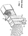
- the mica-tape may be wound around conductors to provide extremely good electrical insulation. An example of this is shown in Fig. 1 . Illustrated here is a coil 13, comprising a plurality of turns of conductors 14, which in the example illustrated here are assembled into a bakelized coil.
- the turn insulation 15 is prepared from a fibrous material or material, for example glass or glass and Dacron which is heat treated.
- Ground insulation for the coil is provided by wrapping one or more layers of composite mica tape 16 about the bakalized coil 14 .
- Such composite tape may be a paper or felt of small mica flakes combined with a pliable backing sheet 18 of, for example, glass fiber cloth or polyethylene glycol terephthalate mat, the layer of mica 20 being bonded thereto by a liquid resinous binder.
- a plurality of layers of the composite tape 16 are wrapped about the coil depending upon voltage requirements.
- a wrapping of an outer tape 21 of a tough fibrous material, for example, glass fiber, may be applied to the coil.
- EP 0 266 602 A1 discloses a coil for arrangement in slots in a stator or rotor of an electrical machine, in particular a high voltage coil, and method for manufacturing the coil.
- the coil comprises a bundle of conductors arranged adjacent to each other. Each conductor is provided with conductor insulation and a main insulation surrounds the bundle for insulation of the bundle against the walls of the machine slot.
- the main insulation comprises a wrapping of a tape- or sheet-formed insulating material, wound in several layers around the conductor bundle, and comprising a layer with small mica flakes which, as well as the space between layers of mica flakes in the wrapping, contains a cured impregnating resin.
- At least that part of the impregnating resin located in the spaces between the mica layers contains particles of a filler material with an intrinsic thermal conductivity of at least 5 W/mK and with a grain size of the particles of 0.1-15 ⁇ m in at least 90 per cent by weight of the filler material.
- a method of impregnating a matrix with a high thermal conductivity filled resin comprising: impregnating said matrix with a high thermal conductivity material loaded resin, wherein said high thermal conductivity material is 5-60% by volume of said loaded resin, to produce a resin impregnated matrix; compressing said resin impregnated matrix by approximately 5-30% wherein distances between said high thermal conductivity materials loaded in said resin are reduced; and curing said resin impregnated matrix; wherein said high thermal conductivity materials comprises at least one of silica, alumina, magnesium oxide, silicon carbide, boron nitride, aluminum nitride, zinc oxide and diamonds and dendrimers of approximately 1-1000 nm in size, and wherein said high thermal conductivity materials have aspect ratios of 10-50.
- thermo conductivity of resins of the prior art limits the efficiency of the electrical system to which the resin impregnated tapes are applied.
- HTC materials are loaded into the resin, which is then impregnated into the insulation tape, or loaded into the insulating tape which is then impregnated with resin.
- the tapes may be impregnated with resin before or after being applied to electrical objects.
- Resin impregnation techniques include VPI and GVPI, discussed more below.
- VPI once a tape is lapped and impregnated it is compressed.
- GVPI the tape layers are compressed and then wound into a slot and subsequently impregnated.
- the compression is mechanical and may be accomplished by a variety of techniques, such as presses, vices, clamps and other devices and techniques such as hydrostatic compression. During the compression stage the taped object may be transferred to a final location.
- the resin in the compressed tape is cured, which effectively locks the position of the HTC materials.
- the resin may be cured in a two stage process, as will be apparent to one of ordinary skill in the art. However, optimal compression of the loaded HTC materials favors a completely uncured resin during the compression stage. Additionally, there may be utilized multiple, discrete compression stages. These multiple compression stages may be performed one after another, or may be separated by other stages, such as relaxation, additional lapping, semi-curing and/or transport.
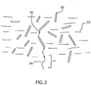
- Fig. 2 Illustrated here are HTC materials 30 loaded into a resinous matrix 32.
- Phonons 34 traveling through the matrix have a mean path length n. This path length can vary depending on the exact composition of the resin matrix, but is generally from 2 to 100 nm, and more typically 5-50nm, for resins such as epoxy resins. Therefore the mean distance between the loaded HTC materials should be on average less than this distance. Note that the distance between the HTC materials can vary in the thickness versus transverse direction of the tape, and it is generally the thickness direction where the spacing needs to be optimalized.
- phonons 34 travel through the resin 32 they will tend to pass along the embedded HTC materials 30. This will increase the local phonon flux since the raw HTC materials will have a thermal conductivity of between 10-1000 W/mK, as opposed to the resin which is about 0.1-0.5 W/mK.
- the phonons 36 pass to the next HTC material if the distance between the materials is less than n, therefore the HTC materials form an interconnecting network.
- Fig. 2 illustrates an idealized path. In practice there will be phonon scattering as the phonons pass between the resin and HTC materials, although the shorter the distance between the materials the less the scattering.
- the amount of HTC materials loaded in the resin could actually be quite low, for example about 10% as illustrated in Fig. 2 .
- the average distances, or length scales, between loaded HTC materials therefore may be slightly greater than n, however, a large percentage will still be less than n.
- the percentage materials that are less than n distance from the next HTC material may be over 50%, or over 75%.
- the average length of the HTC materials may be greater than n, which further aids in phonon transport.
- the resin When the resin is impregnated into the tape, it will fill up the spaces between the tape fibers and substrates.
- the HTC distribution within the tape at this point, however, is often not optimized, and can even have the mean distance between HTC materials greater than n. Then there is compression of the resin impregnated tapes and reduction of the distances between the loaded HTC materials.
- the fibers or particles of the tape act to block some of the HTC materials, particularly if the resin is 30% or more filler.
- the HTC fillers even get pinned to one another.
- the fillers do not react with the resin matrix, however, in some cases the fillers do form covalent bonds with the resin and form more homogeneous matrixes. In a homogenous matrix, the resins that are bound to fillers will be retained better than the unbound resins during compression.
- the amount of compression of the tape is generally about 5-30% of total size of the resin impregnated tape.
- Other fields of use, such as impregnated circuit boards will have similar total compression. Since phonons scatter as they pass between interfaces, such as between the HTC materials and the resin matrix, the shorter the distance between the materials the less the scattering. Therefore greater compression will provide better results as long as the overall integrity of the tape or other impregnated structure is maintained.
- objects lapped with tape are transferred during the compression stage.
- the tapes can be overly compressed and then allowed to relax slightly back to a less compressed state.
- the amount of relaxing is slight, for example 5-50% of the original compression. This allows for proper insertion of a lapped object into a tight spot, such as a slot, without damaging the tape and while maintaining the proper distribution of loaded HTC materials.
- the amount of relaxation in particular cases is kept to 5% or less of the total compression. In cases where additional relaxation is desired, the compression can be reduced before the resin is fully cured.
- resin refers to all resins and epoxy resins, including modified epoxies, polyesters, polyurethanes, polyimides, polyesterimides, polyetherimides, bismaleimides, silicones, polysiloxanes, polybutadienes, cyanate esters, hydrocarbons etc. as well as homogeneous blends of these resins.
- This definition of resins includes additives such as cross-linking agents, accelerators and other catalysts and processing aids.
- Certain resins, such as liquid crystal thermosets (LCT) and 1,2 vinyl polybutadiene combine low molecular weights characteristics with good crosslinking properties.
- the HTC materials loaded into the resins are of a variety of substances that can be added so that they may physically and/or chemically interact with or react with the resins to improve thermal conductivity.
- the HTC materials are dendrimers, and in another case they are nano or micro inorganic fillers having a defined size or shape including high aspect ratio particles with aspect ratios (ratio mean lateral dimension to mean longitudinal dimension) of 3 to 100 or more, with a more particular range of 10-50.
- the HTC materials may have a defined size and shape distribution.
- concentration and relative concentration of the filler particles is chosen to enable a bulk connecting (or so-called percolation) structure to be achieved which confers high thermal conductivity with and without volume filling to achieve a structurally stable discrete two phase composite with enhanced thermal conductivity.
- orientation of the HTC materials increases thermal conductivity.
- surface coating of the HTC materials enhances phonon transport.
- HTC is achieved by surface coating of lower thermal conductivity fillers with metal oxides, carbides or nitrides and mixed systems having high thermal conductivity which are physically or chemically attached to fillers having defined bulk properties, such attachment being achieved by processes such as chemical vapour deposition and physical vapour deposition and also by plasma treatment.
- the HTC materials form essentially homogenous mixtures with the resins, essentially free of undesired microscopic interfaces, variable particle wetting and micro void formation. These homogeneous materials form a continuous-phase material which are non-discrete at length scales shorter than either the phonon wavelength or phonon mean free path in conventional electrical insulating materials.
- intentional interfaces can be placed in the resin structure so as to control dielectric breakdown. In insulating materials, dielectric breakdown will occur given the right conditions.
- dielectric breakdown strength and long term electrical endurance can be enhanced. Increases in dielectric strength will take place in part because of increased densification, the removal of micro voids and a higher level of internal mechanical compression strength.
- phonon transport is enhanced and phonon scattering reduced by ensuring the length scales of the structural elements are shorter than or commensurate with the phonon distribution responsible for thermal transport.
- Larger HTC particulate materials can actually increase phonon transport in their own right, however, smaller HTC materials can alter the nature of the resin matrix, thereby affect a change on the phonon scattering. This may be further assisted by using nano-particles whose matrices are known to exhibit high thermal conductivity and to ensure that the particle size is sufficient to sustain this effect and also to satisfy the length scale requirements for reduced phonon scattering.
- Continuous two-phase organic-inorganic hybrids may be formed by incorporating inorganic nano-particles in linear or crosslinked polymers and thermosetting resins in which nano-particles dimensions are of the order of or less than the polymer or network segmental length (typically 1 to 50 nm). This would include, but is not exclusive to three routes or mechanisms by which this can occur (i) side chain grafting, (ii) inclusive grafting e.g. between two polymer chain ends, (iii) cross linking grafting involving several polymer molecules. These inorganic nano-particles will contain reactive surfaces to form intimate covalently bonded hybrid organic-inorganic homogeneous materials.
- These nano-particles may be alumina, magnesium oxide and zinc oxide and other metal oxides, boron nitride and aluminum nitride and other metal nitrides, silicon carbide and other carbides, diamond of natural or synthetic origin, and any of the various physical forms of each type and other metal carbides and hybrid stoichiometric and non-stoichiometric mixed oxides, nitrides and carbides. Further, these nano-particles will be surface treated to introduce a variety of surface functional groups which are capable of participating in reactions with the host organic polymer or network.
- the volume percentage of the HTC materials in the resin may be up to approximately 60% or more by volume, and more particularly up to approximately 35% by volume.
- the size and shape of the HTC-materials are varied within the same use. Ranges of size and shape are used in the same product.
- a variety of long and shorter variable aspect ratio HTC-materials will enhance the thermal conductivity of a resin matrix, as well as potentially provide enhanced physical properties and performance.
- One aspect that should be observed, however, is that the particle length does not get so long as to cause bridging between layers of substrate/insulation.
- a variety of shapes and length will improve the percolation stability of the HTC-materials by providing a more uniform volume filing and packing density, resulting in a more homogeneous matrix.
- the longer particles are more rod-shaped, while the smaller particles are more spheroidal, platelet or discoid and even cuboids.
- a resin containing HTC-materials could contain about 55-65% by volume 10-50 nm diameter spheroids and about 15-25% by volume 10-50 ⁇ m length rods, with 10-30% volume resin.
- a rod is defined as a particle with a mean aspect ratio of approximately 5 or greater, with particular cases of 10 or greater, though with more particular cases of no greater than 100.
- the axial length of the rods is approximately in the range 10 nm to 100 microns. Smaller rods will percolate a resin matrix better, and have less adverse effect on the viscosity of the resin.
- micro particles form spheroidal and discoid shapes, which have reduced ability to distribute evenly under certain conditions and so may lead to aggregated filamentary structures that reduce the concentration at which percolation occurs.
- the thermal properties of the epoxy resin can be increased, or alternately, the amount of HTC material that needs to be added to the epoxy resin can be reduced.
- the enhanced percolation results in a more even distribution of the HTC materials within the epoxy resin rather than agglomeration which is to be avoided, creating a more homogenous product that is less likely to have undesired interfaces, incomplete particle wetting and micro-void formation.
- aggregated filamentary or dendritic structures rather than globular (dense) aggregates or agglomerates, formed from higher aspect ratio particles confer enhanced thermal conductivity.
- Reactive surface functional groups may be formed from surface groups intrinsic to the inorganic coating or may be achieved by applying additional organic coatings both of which may include hydroxyl, carboxylic, amine, epoxide, silane, vinyl and other groups which will be available for chemical reaction with the host organic matrix. These single or multiple surface coatings and the surface functional groups may be applied using wet chemical methods, non-equilibrium plasma methods including plasma polymerization and chemical vapour and physical vapour deposition, sputter ion plating and electron and ion beam evaporation methods.
- the term substrate refers to the host material that the insulating paper is formed from, while matrix refers to the more complete paper component made out of the substrate. These two terms may be used somewhat interchangeably in the present discussion.
- the increase of thermal conductivity should be accomplished without significantly impairing the electrical properties, such as dissipation factor, or the physical properties of the substrate, such as tensile strength and cohesive properties.
- the physical properties can even be improved in some cases, such as with surface coatings.
- the electrical resistivity of the host matrix can also be enhanced by the addition of HTC materials.
- the HTC materials can be added to the substrate or matrix at one or more of the various stages of manufacture of the insulating paper. Distinct stages in the manufacture of an insulating paper exist. For the purpose of the present discussion, these can be separated into three stages. The raw material stage, the slurry stage, and the paper product stage. For example, a mica paper begins as mica which is converted to flakes then to mica flakelets that are then combined with a liquid into a slurry, which is then run through a machine to produce a mica paper.
- HTC materials can occur at any or all of the production stages. Each of these stages, of course, will comprise of multiple sub-stages at which the HTC material may be added. The process of applying the HTC materials at the various stages will have to account for the difference in physical characteristics of the host matrix at these various stages. For example, adding the HTC materials to loose mica flakes or mica flakelets is different than adding the materials to the mica in the slurry or the paper product. HTC materials may also be present in other component parts of the finished insulating tape, such as the backing fabric, or the interlayer bonding resins.
- the process of manufacture of insulating paper combines thermal, chemical, and mechanical treatments individually or in combinations, to produce a pulp that is then transformed into sheets that make up the paper.
- HTC-materials can be added to the raw material stage either in the dry form or contained in a liquid or other medium.
- the HTC material is added to the substrate, such as dry mica flakelets, and intermixed to form, in one instance, a homogeneous distribution within the substrate. Methods such as heat may be used to remove the liquid medium that delivers the HTC materials to the substrate.
- HTC materials are incorporated into the matrix at the slurry stage by adding them to a suspension in an agglomerated or non-agglomerated form in a liquid carrier. Aggregation of the HTC material is generally not preferred at this stage but in some cases it may be used depending on the nature of the aggregate structure. Surfactants, chemical surface preparation, or pH control may be used to ensure the particles do not aggregate or that they aggregate in particular ways. If the HTC are to some degree self aligning or can be aligned by external forces then full dispersion on mixing may not be necessary.
- the fillers may either be added as a powder or as a suspension in a liquid phase.
- the liquid can be of a variety of types used in the art, though water is typical.
- the water itself can be deionized, demineralized, or have additives to control its pH value.
- the fillers may be incorporated into a suitable solvent as a suspension.
- suitable solvent such as hexane, toluene, methylethylketone etc.
- the HTC material be uniformly distributed in the liquid as a non-aggregated suspension.
- the size distribution of the particles may be chosen to fulfill the desired objective in relation to the void size distribution in host matrix.
- the HTC material size and shape distribution may be employed to influence the thermal conductivity and other physical properties, and use can be made of the different close packing behavior of such components or of their different aggregation or self-assembling behavior, to achieve this.
- the solvents may also contain one or more accelerators, such a zinc naphthenate and other metal-salts or organometallics, which may be used to accelerate the reaction of a later impregnated resin.
- accelerators such as zinc naphthenate and other metal-salts or organometallics, which may be used to accelerate the reaction of a later impregnated resin.
- HTC material can be added together with the accelerator in a common solvent or accelerator.
- HTC materials are inserted into a host matrix, or substrate, such as a mica and polyester.
- substrate such as a mica and polyester.
- Other substrate components include glass flakes, and KaptonTM, which is a polyimide, or MylarTM which is a polyester such as polyethylene terephthalate.
- the HTC materials can be applied to any and all external and internal surfaces. Although flakes are a common first stage substrate, some types of substrate materials may use different physical formations, or even combinations of physical formations that can form composite paper that can be multi-layered or continuous.
- HTC materials either as a filler in an impregnating resin, or as an integral part of the insulating paper that is later impregnated with resin, both may be used in conjunction with one another.
- the dispersion of HTC materials in the final product can be increased.
- the host material can be compressed both prior to and/or after resin impregnation.
- VPI and GVPI Types of resin impregnation used with stator coils are known as VPI and GVPI.
- Tape is wrapped around the coil and then impregnated with low viscosity liquid insulation resin by vacuum-pressure impregnation (VPI). That process consists of evacuating a chamber containing the coil in order to remove air and moisture trapped in the mica tape, then introducing the insulation resin under pressure to impregnate the mica tape completely with resin thus eliminating voids, producing resinous insulation in a mica matrix. A compression of about 20% is particular to the VPI process in some cases. After this is completed, the coils are heated to cure the resin.
- the resin may contain an accelerator or the tape may have one in it.
- GVPI global VPI
Landscapes
- Chemical & Material Sciences (AREA)
- Engineering & Computer Science (AREA)
- Polymers & Plastics (AREA)
- Organic Chemistry (AREA)
- Health & Medical Sciences (AREA)
- Chemical Kinetics & Catalysis (AREA)
- Medicinal Chemistry (AREA)
- Materials Engineering (AREA)
- Manufacturing & Machinery (AREA)
- Ceramic Engineering (AREA)
- Inorganic Chemistry (AREA)
- Power Engineering (AREA)
- Insulating Bodies (AREA)
- Compositions Of Macromolecular Compounds (AREA)
- Reinforced Plastic Materials (AREA)
Claims (3)
- Procédé d'imprégnation d'une matrice avec une résine chargée à haute conductivité thermique consistant :à imprégner ladite matrice d'une résine chargée en matériau à haute conductivité thermique, étant entendu que ledit matériau à haute conductivité thermique fait 5-60 % en volume de ladite résine chargée, pour produire une matrice imprégnée de résine ;à comprimer ladite matrice imprégnée de résine d'approximativement 5-30 %, étant entendu que les distances entre lesdits matériaux à haute conductivité thermique chargés dans ladite résine sont réduites, età durcir ladite matrice imprégnée de résine,étant entendu que lesdits matériaux à haute conductivité thermique consistent au moins en silice, alumine, oxyde de magnésium, carbure de silicium, nitrure de bore, nitrure d'aluminium, oxyde de zinc ou diamants et en dendrimères faisant approximativement 1-1000 nm de taille, et étant entendu que lesdits matériaux à haute conductivité thermique ont des rapports de dimensions de 10-50.
- Procédé selon la revendication 1, dans lequel les distances entre lesdits matériaux à haute conductivité thermique chargés dans ladite résine font approximativement 5-50 nm.
- Procédé selon la revendication 1, dans lequel on comprime ladite matrice imprégnée de résine au moins deux fois avant de la durcir.
Applications Claiming Priority (3)
| Application Number | Priority Date | Filing Date | Title |
|---|---|---|---|
| US58002304P | 2004-06-15 | 2004-06-15 | |
| US11/106,845 US7553438B2 (en) | 2004-06-15 | 2005-04-15 | Compression of resin impregnated insulating tapes |
| PCT/US2005/020560 WO2006002012A1 (fr) | 2004-06-15 | 2005-06-13 | Compression de bandes d'isolation impregnees de resine |
Publications (2)
| Publication Number | Publication Date |
|---|---|
| EP1761992A1 EP1761992A1 (fr) | 2007-03-14 |
| EP1761992B1 true EP1761992B1 (fr) | 2017-09-27 |
Family
ID=34972132
Family Applications (1)
| Application Number | Title | Priority Date | Filing Date |
|---|---|---|---|
| EP05758580.4A Expired - Lifetime EP1761992B1 (fr) | 2004-06-15 | 2005-06-13 | Compression de bandes d'isolation impregnees de resine |
Country Status (5)
| Country | Link |
|---|---|
| US (1) | US7553438B2 (fr) |
| EP (1) | EP1761992B1 (fr) |
| JP (1) | JP2008502775A (fr) |
| KR (1) | KR101168781B1 (fr) |
| WO (1) | WO2006002012A1 (fr) |
Families Citing this family (57)
| Publication number | Priority date | Publication date | Assignee | Title |
|---|---|---|---|---|
| US7781063B2 (en) | 2003-07-11 | 2010-08-24 | Siemens Energy, Inc. | High thermal conductivity materials with grafted surface functional groups |
| US7033670B2 (en) * | 2003-07-11 | 2006-04-25 | Siemens Power Generation, Inc. | LCT-epoxy polymers with HTC-oligomers and method for making the same |
| US7592045B2 (en) * | 2004-06-15 | 2009-09-22 | Siemens Energy, Inc. | Seeding of HTC fillers to form dendritic structures |
| US7553438B2 (en) | 2004-06-15 | 2009-06-30 | Siemens Energy, Inc. | Compression of resin impregnated insulating tapes |
| US20050274774A1 (en) | 2004-06-15 | 2005-12-15 | Smith James D | Insulation paper with high thermal conductivity materials |
| KR101207775B1 (ko) * | 2004-06-15 | 2012-12-04 | 지멘스 에너지, 인코포레이티드 | 수지들 내에 배열되는 고열전도성 물질들 |
| US7553781B2 (en) | 2004-06-15 | 2009-06-30 | Siemens Energy, Inc. | Fabrics with high thermal conductivity coatings |
| US20050277721A1 (en) | 2004-06-15 | 2005-12-15 | Siemens Westinghouse Power Corporation | High thermal conductivity materials aligned within resins |
| US8216672B2 (en) * | 2004-06-15 | 2012-07-10 | Siemens Energy, Inc. | Structured resin systems with high thermal conductivity fillers |
| US7776392B2 (en) * | 2005-04-15 | 2010-08-17 | Siemens Energy, Inc. | Composite insulation tape with loaded HTC materials |
| US7651963B2 (en) * | 2005-04-15 | 2010-01-26 | Siemens Energy, Inc. | Patterning on surface with high thermal conductivity materials |
| US7846853B2 (en) | 2005-04-15 | 2010-12-07 | Siemens Energy, Inc. | Multi-layered platelet structure |
| TWI339847B (en) * | 2005-06-10 | 2011-04-01 | Delta Electronics Inc | Inductor and magnetic body thereof |
| US7851059B2 (en) | 2005-06-14 | 2010-12-14 | Siemens Energy, Inc. | Nano and meso shell-core control of physical properties and performance of electrically insulating composites |
| US20070026221A1 (en) * | 2005-06-14 | 2007-02-01 | Siemens Power Generation, Inc. | Morphological forms of fillers for electrical insulation |
| US7955661B2 (en) | 2005-06-14 | 2011-06-07 | Siemens Energy, Inc. | Treatment of micropores in mica materials |
| US7781057B2 (en) | 2005-06-14 | 2010-08-24 | Siemens Energy, Inc. | Seeding resins for enhancing the crystallinity of polymeric substructures |
| US7655295B2 (en) | 2005-06-14 | 2010-02-02 | Siemens Energy, Inc. | Mix of grafted and non-grafted particles in a resin |
| US8357433B2 (en) | 2005-06-14 | 2013-01-22 | Siemens Energy, Inc. | Polymer brushes |
| KR101424564B1 (ko) | 2006-06-22 | 2014-08-06 | 에이엠에스 리서치 코포레이션 | 인장조절가능한 실금용슬링조립체 |
| US7547847B2 (en) * | 2006-09-19 | 2009-06-16 | Siemens Energy, Inc. | High thermal conductivity dielectric tape |
| US8395296B2 (en) * | 2009-09-16 | 2013-03-12 | Siemens Energy, Inc. | Tape structure with conductive outer side and electrically insulating inner side |
| MX2012011571A (es) | 2010-05-04 | 2013-02-12 | Remy Technologies Llc | Sistema y metodo de enfriamiento de maquina electrica. |
| DE102010019721A1 (de) * | 2010-05-07 | 2011-11-10 | Siemens Aktiengesellschaft | Elektrisches Isoliermaterial, Isolationspapier und Isolationsband für eine Hochspannungsrotationsmaschine |
| CN103038983B (zh) | 2010-06-04 | 2016-08-10 | 瑞美技术有限责任公司 | 电机冷却系统及方法 |
| US8519581B2 (en) | 2010-06-08 | 2013-08-27 | Remy Technologies, Llc | Electric machine cooling system and method |
| JP2013528353A (ja) | 2010-06-08 | 2013-07-08 | レミー テクノロジーズ リミテッド ライアビリティー カンパニー | 電気機械冷却システム及び方法 |
| US8456046B2 (en) | 2010-06-08 | 2013-06-04 | Remy Technologies, Llc | Gravity fed oil cooling for an electric machine |
| US8614538B2 (en) | 2010-06-14 | 2013-12-24 | Remy Technologies, Llc | Electric machine cooling system and method |
| US8482169B2 (en) | 2010-06-14 | 2013-07-09 | Remy Technologies, Llc | Electric machine cooling system and method |
| US8446056B2 (en) | 2010-09-29 | 2013-05-21 | Remy Technologies, Llc | Electric machine cooling system and method |
| US8508085B2 (en) | 2010-10-04 | 2013-08-13 | Remy Technologies, Llc | Internal cooling of stator assembly in an electric machine |
| US8492952B2 (en) | 2010-10-04 | 2013-07-23 | Remy Technologies, Llc | Coolant channels for electric machine stator |
| US8593021B2 (en) | 2010-10-04 | 2013-11-26 | Remy Technologies, Llc | Coolant drainage system and method for electric machines |
| US8395287B2 (en) | 2010-10-04 | 2013-03-12 | Remy Technologies, Llc | Coolant channels for electric machine stator |
| US8648506B2 (en) | 2010-11-09 | 2014-02-11 | Remy Technologies, Llc | Rotor lamination cooling system and method |
| US8497608B2 (en) | 2011-01-28 | 2013-07-30 | Remy Technologies, Llc | Electric machine cooling system and method |
| WO2012145302A2 (fr) | 2011-04-18 | 2012-10-26 | Remy Technologies, Llc | Système et procédé de refroidissement d'un module de machine électrique |
| US8692425B2 (en) | 2011-05-10 | 2014-04-08 | Remy Technologies, Llc | Cooling combinations for electric machines |
| WO2012167274A1 (fr) | 2011-06-03 | 2012-12-06 | Remy Technologies, Llc | Système et procédé de refroidissement d'un module de machine électrique |
| US9041260B2 (en) | 2011-07-08 | 2015-05-26 | Remy Technologies, Llc | Cooling system and method for an electronic machine |
| US8803381B2 (en) | 2011-07-11 | 2014-08-12 | Remy Technologies, Llc | Electric machine with cooling pipe coiled around stator assembly |
| US8546982B2 (en) | 2011-07-12 | 2013-10-01 | Remy Technologies, Llc | Electric machine module cooling system and method |
| DE102011079489A1 (de) * | 2011-07-20 | 2013-01-24 | Siemens Aktiengesellschaft | Verfahren zum Herstellen eines Bandes für ein elektrisches Isolationssystem |
| US9048710B2 (en) | 2011-08-29 | 2015-06-02 | Remy Technologies, Llc | Electric machine module cooling system and method |
| US8975792B2 (en) | 2011-09-13 | 2015-03-10 | Remy Technologies, Llc | Electric machine module cooling system and method |
| US9099900B2 (en) | 2011-12-06 | 2015-08-04 | Remy Technologies, Llc | Electric machine module cooling system and method |
| US9331543B2 (en) | 2012-04-05 | 2016-05-03 | Remy Technologies, Llc | Electric machine module cooling system and method |
| US10069375B2 (en) | 2012-05-02 | 2018-09-04 | Borgwarner Inc. | Electric machine module cooling system and method |
| CN102800445B (zh) * | 2012-08-05 | 2016-07-20 | 哈尔滨理工大学 | 高导热高强度多胶粉云母带的制备方法 |
| US20150201587A1 (en) * | 2012-08-18 | 2015-07-23 | Scr Engineers Ltd | Cow retrieval system |
| US9928935B2 (en) * | 2013-05-31 | 2018-03-27 | General Electric Company | Electrical insulation system |
| DE102014204416A1 (de) | 2014-03-11 | 2015-09-17 | Siemens Aktiengesellschaft | Isolationsband, dessen Verwendung als elektrische Isolation für elektrische Maschinen, die elektrische Isolation und Verfahren zur Herstellung des Isolationsbandes |
| US9879163B2 (en) | 2014-06-06 | 2018-01-30 | General Electric Company | Composition for bonding windings or core laminates in an electrical machine, and associated method |
| US9911521B2 (en) | 2014-06-06 | 2018-03-06 | General Electric Company | Curable composition for electrical machine, and associated method |
| EP3565090A1 (fr) * | 2018-05-04 | 2019-11-06 | Siemens Aktiengesellschaft | Système d'isolation électrique d'un moteur électrique et procédé de fabrication correspondant |
| US11677282B2 (en) * | 2020-02-27 | 2023-06-13 | Accelerated Systems Inc. | Composite material for thermal management in an electric motor |
Family Cites Families (113)
| Publication number | Priority date | Publication date | Assignee | Title |
|---|---|---|---|---|
| US3246271A (en) * | 1965-04-16 | 1966-04-12 | Westinghouse Electric Corp | Paper insulation for transformers |
| JPS5232062B2 (fr) * | 1972-12-25 | 1977-08-19 | ||
| CA1016586A (en) * | 1974-02-18 | 1977-08-30 | Canadian General Electric Company Limited | Grounding of outer winding insulation to cores in dynamoelectric machines |
| US3974302A (en) * | 1974-11-26 | 1976-08-10 | Westinghouse Electric Corporation | Method of making patterned dry resin coated sheet insulation |
| US4160926A (en) * | 1975-06-20 | 1979-07-10 | The Epoxylite Corporation | Materials and impregnating compositions for insulating electric machines |
| JPS553064A (en) | 1978-06-22 | 1980-01-10 | Fujitsu Ltd | Binary/decimal adder device |
| US4760296A (en) * | 1979-07-30 | 1988-07-26 | General Electric Company | Corona-resistant insulation, electrical conductors covered therewith and dynamoelectric machines and transformers incorporating components of such insulated conductors |
| US4335367A (en) * | 1979-08-17 | 1982-06-15 | Tokyo Shibaura Denki Kabushiki Kaisha | Electrically insulated coil |
| US4361661A (en) * | 1980-05-22 | 1982-11-30 | Western Electric Company, Incorporated | Thermal backfill composition method |
| US4400226A (en) * | 1981-07-16 | 1983-08-23 | General Electric Company | Method of making an insulated electromagnetic coil |
| US4427740A (en) * | 1982-04-09 | 1984-01-24 | Westinghouse Electric Corp. | High maximum service temperature low cure temperature non-linear electrical grading coatings resistant to V.P.I. resins containing highly reactive components |
| DE3411473A1 (de) | 1984-03-28 | 1985-10-10 | Siemens AG, 1000 Berlin und 8000 München | Form- und ueberzugsmassen |
| US4634911A (en) * | 1985-04-16 | 1987-01-06 | Westinghouse Electric Corp. | High voltage dynamoelectric machine with selectively increased coil turn-to-turn insulation strength |
| US4694064A (en) * | 1986-02-28 | 1987-09-15 | The Dow Chemical Company | Rod-shaped dendrimer |
| US4704322A (en) * | 1986-09-22 | 1987-11-03 | Essex Group, Inc. | Resin rich mica tape |
| SE455246B (sv) * | 1986-10-22 | 1988-06-27 | Asea Ab | Herva for anordnande i spar i en stator eller rotor i en elektrisk maskin och sett att tillverka en sadan herva |
| US5011872A (en) * | 1987-12-21 | 1991-04-30 | The Carborudum Company | Thermally conductive ceramic/polymer composites |
| FI105605B (fi) | 1989-04-27 | 2000-09-15 | Siemens Ag | Planarisoiva eriste |
| JP2862928B2 (ja) | 1990-01-05 | 1999-03-03 | 東芝ケミカル株式会社 | 封止用樹脂組成物及び半導体封止装置 |
| US5126192A (en) * | 1990-01-26 | 1992-06-30 | International Business Machines Corporation | Flame retardant, low dielectric constant microsphere filled laminate |
| US5352493A (en) * | 1991-05-03 | 1994-10-04 | Veniamin Dorfman | Method for forming diamond-like nanocomposite or doped-diamond-like nanocomposite films |
| US5281388A (en) * | 1992-03-20 | 1994-01-25 | Mcdonnell Douglas Corporation | Resin impregnation process for producing a resin-fiber composite |
| DE4244298C2 (de) | 1992-12-28 | 2003-02-27 | Alstom | Isolierband und Verfahren zu seiner Herstellung |
| JPH06313267A (ja) | 1993-04-28 | 1994-11-08 | Washi Kosan Kk | 高熱伝導性繊維あるいは繊維製品 |
| US5510174A (en) * | 1993-07-14 | 1996-04-23 | Chomerics, Inc. | Thermally conductive materials containing titanium diboride filler |
| US5578901A (en) * | 1994-02-14 | 1996-11-26 | E. I. Du Pont De Nemours And Company | Diamond fiber field emitters |
| US5723920A (en) * | 1994-10-12 | 1998-03-03 | General Electric Company | Stator bars internally graded with conductive binder tape |
| NL9500509A (nl) | 1995-03-14 | 1996-10-01 | Vicair B V | Ondersteuningsinrichting zoals bijvoorbeeld een kussen. |
| US5801334A (en) * | 1995-08-24 | 1998-09-01 | Theodorides; Demetrius C. | Conductor (turn) insulation system for coils in high voltage machines |
| AU710700B2 (en) * | 1995-12-01 | 1999-09-30 | E.I. Du Pont De Nemours And Company | Diamond-like-carbon coated aramid fibers having improved mechanical properties |
| US5780119A (en) * | 1996-03-20 | 1998-07-14 | Southwest Research Institute | Treatments to reduce friction and wear on metal alloy components |
| US6130495A (en) * | 1996-05-15 | 2000-10-10 | Siemens Aktiengesellschaft | Supporting element for an electric winding, turbogenerator and method of producing a corona shield |
| JP3201262B2 (ja) * | 1996-05-30 | 2001-08-20 | 株式会社日立製作所 | 熱硬化性樹脂組成物,電機絶縁線輪,回転電機及びその製造方法 |
| US6344271B1 (en) * | 1998-11-06 | 2002-02-05 | Nanoenergy Corporation | Materials and products using nanostructured non-stoichiometric substances |
| JPH1088201A (ja) | 1996-09-10 | 1998-04-07 | Hiroshi Nakazawa | レーザ応用粉体成形加工方法 |
| US6255738B1 (en) * | 1996-09-30 | 2001-07-03 | Tessera, Inc. | Encapsulant for microelectronic devices |
| US5904984A (en) * | 1996-10-17 | 1999-05-18 | Siemens Westinghouse Power Corporation | Electrical insulation using liquid crystal thermoset epoxy resins |
| JP3660765B2 (ja) * | 1996-10-31 | 2005-06-15 | デュポン帝人アドバンスドペーパー株式会社 | アラミド複合体シートの製造方法 |
| US6359232B1 (en) * | 1996-12-19 | 2002-03-19 | General Electric Company | Electrical insulating material and stator bar formed therewith |
| US5878620A (en) * | 1997-01-23 | 1999-03-09 | Schlege Systems, Inc. | Conductive fabric sensor for vehicle seats |
| JPH10211659A (ja) | 1997-01-31 | 1998-08-11 | Toyota Motor Corp | 積層造形方法 |
| US6103382A (en) * | 1997-03-14 | 2000-08-15 | Siemens Westinghouse Power Corporation | Catalyzed mica tapes for electrical insulation |
| US6160042A (en) * | 1997-05-01 | 2000-12-12 | Edison Polymer Innovation Corporation | Surface treated boron nitride for forming a low viscosity high thermal conductivity polymer based boron nitride composition and method |
| DE19720555A1 (de) * | 1997-05-16 | 1998-11-19 | Abb Research Ltd | Statorwicklungsisolierung |
| RU2114210C1 (ru) * | 1997-05-30 | 1998-06-27 | Валерий Павлович Гончаренко | Способ формирования углеродного алмазоподобного покрытия в вакууме |
| US6821672B2 (en) * | 1997-09-02 | 2004-11-23 | Kvg Technologies, Inc. | Mat of glass and other fibers and method for producing it |
| EP1029352A1 (fr) | 1997-11-13 | 2000-08-23 | Bp Amoco Corporation | Appareil de gestion thermique a caloduc |
| US6015597A (en) * | 1997-11-26 | 2000-01-18 | 3M Innovative Properties Company | Method for coating diamond-like networks onto particles |
| US6265068B1 (en) * | 1997-11-26 | 2001-07-24 | 3M Innovative Properties Company | Diamond-like carbon coatings on inorganic phosphors |
| JP3745383B2 (ja) * | 1997-12-18 | 2006-02-15 | 三菱電機株式会社 | 回転電機の固定子コイル |
| US5938934A (en) * | 1998-01-13 | 1999-08-17 | Dow Corning Corporation | Dendrimer-based nanoscopic sponges and metal composites |
| JPH11234938A (ja) * | 1998-02-13 | 1999-08-27 | Hitachi Ltd | 高圧回転電機およびその製造方法 |
| US6153721A (en) * | 1998-02-26 | 2000-11-28 | Honeywell International Inc. | Preparation of polyindanebisphenols and polymers derived therefrom |
| US6288341B1 (en) * | 1998-02-27 | 2001-09-11 | Hitachi, Ltd. | Insulating material windings using same and a manufacturing method thereof |
| US6396864B1 (en) * | 1998-03-13 | 2002-05-28 | Jds Uniphase Corporation | Thermally conductive coatings for light emitting devices |
| DE69925528T2 (de) * | 1998-03-19 | 2006-01-26 | Hitachi, Ltd. | Wärmeleitfähige, elektrisch nicht leitende Zusammensetzung |
| DE19850826A1 (de) * | 1998-11-04 | 2000-05-11 | Basf Ag | Als Separatoren in elektrochemischen Zellen geeignete Verbundkörper |
| US6242825B1 (en) * | 1998-11-25 | 2001-06-05 | Hitachi, Ltd. | Electric rotating machine with reduced thickness and volume of insulation |
| US6048919A (en) * | 1999-01-29 | 2000-04-11 | Chip Coolers, Inc. | Thermally conductive composite material |
| ATE464339T1 (de) * | 1999-02-16 | 2010-04-15 | Dendritic Nanotechnologies Inc | Kern-schale tectodendrimere |
| US6572935B1 (en) | 1999-03-13 | 2003-06-03 | The Regents Of The University Of California | Optically transparent, scratch-resistant, diamond-like carbon coatings |
| US6238790B1 (en) * | 1999-05-26 | 2001-05-29 | Siemens Westinghouse Power Corporation | Superdielectric high voltage insulation for dynamoelectric machinery |
| EP1220240B1 (fr) | 1999-08-27 | 2009-11-25 | Hitachi, Ltd. | Materiau isolant, enroulement electrique et leur procede de fabrication |
| AU2905901A (en) * | 1999-11-30 | 2001-06-12 | Regents Of The University Of California, The | Method for producing fluorinated diamond-like carbon films |
| EP1256124A1 (fr) * | 2000-02-16 | 2002-11-13 | Fullerene International Corporation | Structures de nanotubes a revetement diamant/carbone pour emission de champ electronique efficace |
| US6190775B1 (en) * | 2000-02-24 | 2001-02-20 | Siemens Westinghouse Power Corporation | Enhanced dielectric strength mica tapes |
| TW555794B (en) * | 2000-02-29 | 2003-10-01 | Shinetsu Chemical Co | Method for the preparation of low specific gravity silicone rubber elastomers |
| WO2001068749A1 (fr) | 2000-03-16 | 2001-09-20 | Ppg Industries Ohio, Inc. | Torons de fibres de verre impregnees et produits comprenant ces derniers |
| FR2808622B1 (fr) | 2000-05-04 | 2006-09-08 | Bollore | Generateur electrochimique a electrolyte polymerique comprenant des polymeres fluores |
| US20020058140A1 (en) * | 2000-09-18 | 2002-05-16 | Dana David E. | Glass fiber coating for inhibiting conductive anodic filament formation in electronic supports |
| JP3662499B2 (ja) | 2001-01-17 | 2005-06-22 | トヨタ自動車株式会社 | 無機有機ハイブリッド材料 |
| JP3576119B2 (ja) * | 2001-04-27 | 2004-10-13 | 株式会社東芝 | 回転電機のコイル及びこのコイルの絶縁に用いられるマイカーテープ |
| US20030040563A1 (en) * | 2001-08-23 | 2003-02-27 | Sagal E. Mikhail | Substantially non-abrasive thermally conductive polymer composition containing boron nitride |
| CN1321232C (zh) * | 2001-09-20 | 2007-06-13 | 昭和电工株式会社 | 细碳纤维混合物及其组合物 |
| EP1300439A1 (fr) | 2001-09-26 | 2003-04-09 | Abb Research Ltd. | Charge de renforcement et son utilisation dans des isolateurs électriques |
| WO2003040445A1 (fr) | 2001-11-07 | 2003-05-15 | Showa Denko K.K. | Fibre de carbone fine, son procede de production et son utilisation |
| US6746758B2 (en) * | 2002-02-25 | 2004-06-08 | Hitachi, Ltd. | Insulating material and electric machine winding and method for manufacturing the same |
| WO2003078652A2 (fr) * | 2002-03-15 | 2003-09-25 | Nanomix, Inc. | Modification de selectivite pour la detection d'ensembles de dispositif s a nanostructure |
| US7524557B2 (en) * | 2002-07-04 | 2009-04-28 | Kabushiki Kaisha Toshiba | Highly heat conductive insulating member, method of manufacturing the same and electromagnetic device |
| CN1324615C (zh) | 2002-07-04 | 2007-07-04 | 株式会社东芝 | 高导热性绝缘部件及其制造方法、电磁线圈 |
| JP4563662B2 (ja) | 2002-07-17 | 2010-10-13 | パナソニック株式会社 | 記録媒体不正使用防止システム |
| JP2004051852A (ja) | 2002-07-22 | 2004-02-19 | Polymatech Co Ltd | 熱伝導性高分子成形体及びその製造方法 |
| CN1723250A (zh) * | 2002-12-10 | 2006-01-18 | 西巴特殊化学品控股有限公司 | 基于涂覆有SiOz(0.70≤z≤2.0)的铝的薄片形式的颜料 |
| JP2004250665A (ja) | 2003-01-30 | 2004-09-09 | Suzuka Fuji Xerox Co Ltd | 耐熱性熱伝導性材料 |
| US7013965B2 (en) * | 2003-04-29 | 2006-03-21 | General Electric Company | Organic matrices containing nanomaterials to enhance bulk thermal conductivity |
| JP3843967B2 (ja) | 2003-06-11 | 2006-11-08 | 三菱電機株式会社 | 絶縁コイルの製造方法 |
| US7033670B2 (en) * | 2003-07-11 | 2006-04-25 | Siemens Power Generation, Inc. | LCT-epoxy polymers with HTC-oligomers and method for making the same |
| US7781063B2 (en) | 2003-07-11 | 2010-08-24 | Siemens Energy, Inc. | High thermal conductivity materials with grafted surface functional groups |
| US7042346B2 (en) * | 2003-08-12 | 2006-05-09 | Gaige Bradley Paulsen | Radio frequency identification parts verification system and method for using same |
| US20050116336A1 (en) * | 2003-09-16 | 2005-06-02 | Koila, Inc. | Nano-composite materials for thermal management applications |
| JP4599063B2 (ja) | 2004-01-15 | 2010-12-15 | 株式会社東芝 | コイル巻回用絶縁テープ |
| US20050236606A1 (en) * | 2004-04-26 | 2005-10-27 | Certainteed Corporation | Flame resistant fibrous insulation and methods of making the same |
| US20050277721A1 (en) * | 2004-06-15 | 2005-12-15 | Siemens Westinghouse Power Corporation | High thermal conductivity materials aligned within resins |
| US7268293B2 (en) * | 2004-06-15 | 2007-09-11 | Siemen Power Generation, Inc. | Surface coating of lapped insulation tape |
| US7553438B2 (en) | 2004-06-15 | 2009-06-30 | Siemens Energy, Inc. | Compression of resin impregnated insulating tapes |
| KR101207775B1 (ko) | 2004-06-15 | 2012-12-04 | 지멘스 에너지, 인코포레이티드 | 수지들 내에 배열되는 고열전도성 물질들 |
| US20050277349A1 (en) * | 2004-06-15 | 2005-12-15 | Siemens Westinghouse Power Corporation | High thermal conductivity materials incorporated into resins |
| US7553781B2 (en) * | 2004-06-15 | 2009-06-30 | Siemens Energy, Inc. | Fabrics with high thermal conductivity coatings |
| US20080050580A1 (en) * | 2004-06-15 | 2008-02-28 | Stevens Gary C | High Thermal Conductivity Mica Paper Tape |
| US7776392B2 (en) * | 2005-04-15 | 2010-08-17 | Siemens Energy, Inc. | Composite insulation tape with loaded HTC materials |
| US7592045B2 (en) | 2004-06-15 | 2009-09-22 | Siemens Energy, Inc. | Seeding of HTC fillers to form dendritic structures |
| US20050274774A1 (en) | 2004-06-15 | 2005-12-15 | Smith James D | Insulation paper with high thermal conductivity materials |
| US8216672B2 (en) * | 2004-06-15 | 2012-07-10 | Siemens Energy, Inc. | Structured resin systems with high thermal conductivity fillers |
| US7180409B2 (en) * | 2005-03-11 | 2007-02-20 | Temic Automotive Of North America, Inc. | Tire tread wear sensor system |
| US7651963B2 (en) * | 2005-04-15 | 2010-01-26 | Siemens Energy, Inc. | Patterning on surface with high thermal conductivity materials |
| US7846853B2 (en) * | 2005-04-15 | 2010-12-07 | Siemens Energy, Inc. | Multi-layered platelet structure |
| US20060234027A1 (en) * | 2005-04-18 | 2006-10-19 | Huusken Robert W | Fire retardant laminate |
| US7781057B2 (en) | 2005-06-14 | 2010-08-24 | Siemens Energy, Inc. | Seeding resins for enhancing the crystallinity of polymeric substructures |
| US7955661B2 (en) * | 2005-06-14 | 2011-06-07 | Siemens Energy, Inc. | Treatment of micropores in mica materials |
| US7655295B2 (en) | 2005-06-14 | 2010-02-02 | Siemens Energy, Inc. | Mix of grafted and non-grafted particles in a resin |
| US8357433B2 (en) * | 2005-06-14 | 2013-01-22 | Siemens Energy, Inc. | Polymer brushes |
| US20070026221A1 (en) * | 2005-06-14 | 2007-02-01 | Siemens Power Generation, Inc. | Morphological forms of fillers for electrical insulation |
| US7547847B2 (en) * | 2006-09-19 | 2009-06-16 | Siemens Energy, Inc. | High thermal conductivity dielectric tape |
-
2005
- 2005-04-15 US US11/106,845 patent/US7553438B2/en active Active
- 2005-06-13 JP JP2007516576A patent/JP2008502775A/ja active Pending
- 2005-06-13 EP EP05758580.4A patent/EP1761992B1/fr not_active Expired - Lifetime
- 2005-06-13 WO PCT/US2005/020560 patent/WO2006002012A1/fr not_active Ceased
- 2005-06-13 KR KR1020067025064A patent/KR101168781B1/ko not_active Expired - Fee Related
Non-Patent Citations (1)
| Title |
|---|
| None * |
Also Published As
| Publication number | Publication date |
|---|---|
| EP1761992A1 (fr) | 2007-03-14 |
| JP2008502775A (ja) | 2008-01-31 |
| KR20070037574A (ko) | 2007-04-05 |
| US7553438B2 (en) | 2009-06-30 |
| US20050274450A1 (en) | 2005-12-15 |
| WO2006002012A1 (fr) | 2006-01-05 |
| KR101168781B1 (ko) | 2012-07-25 |
Similar Documents
| Publication | Publication Date | Title |
|---|---|---|
| US7553438B2 (en) | Compression of resin impregnated insulating tapes | |
| US8685534B2 (en) | High thermal conductivity materials aligned within resins | |
| EP1766636B1 (fr) | Materiaux a conductivite thermique elevee alignes avec des resines | |
| US8216672B2 (en) | Structured resin systems with high thermal conductivity fillers | |
| US7592045B2 (en) | Seeding of HTC fillers to form dendritic structures | |
| US7781063B2 (en) | High thermal conductivity materials with grafted surface functional groups | |
| US8039530B2 (en) | High thermal conductivity materials with grafted surface functional groups | |
| EP2311171B1 (fr) | Bobine de stator à dissipation thermique améliorée | |
| US7846853B2 (en) | Multi-layered platelet structure | |
| JP5108511B2 (ja) | 樹脂に組込まれた高熱伝導性材料 | |
| EP2001675B1 (fr) | Procede de fabrication d'un ruban isolant composite charge de materiaux htc | |
| US20100120928A1 (en) | Mix of grafted and non-grafted particles in a resin | |
| US20070026221A1 (en) | Morphological forms of fillers for electrical insulation |
Legal Events
| Date | Code | Title | Description |
|---|---|---|---|
| PUAI | Public reference made under article 153(3) epc to a published international application that has entered the european phase |
Free format text: ORIGINAL CODE: 0009012 |
|
| 17P | Request for examination filed |
Effective date: 20070111 |
|
| AK | Designated contracting states |
Kind code of ref document: A1 Designated state(s): CH DE FR GB IT LI |
|
| DAX | Request for extension of the european patent (deleted) | ||
| RBV | Designated contracting states (corrected) |
Designated state(s): CH DE FR GB IT LI |
|
| 17Q | First examination report despatched |
Effective date: 20100520 |
|
| RAP1 | Party data changed (applicant data changed or rights of an application transferred) |
Owner name: SIEMENS ENERGY, INC. |
|
| STAA | Information on the status of an ep patent application or granted ep patent |
Free format text: STATUS: EXAMINATION IS IN PROGRESS |
|
| REG | Reference to a national code |
Ref country code: DE Ref legal event code: R079 Ref document number: 602005052808 Country of ref document: DE Free format text: PREVIOUS MAIN CLASS: H02K0003300000 Ipc: H01B0003120000 |
|
| GRAP | Despatch of communication of intention to grant a patent |
Free format text: ORIGINAL CODE: EPIDOSNIGR1 |
|
| STAA | Information on the status of an ep patent application or granted ep patent |
Free format text: STATUS: GRANT OF PATENT IS INTENDED |
|
| RIC1 | Information provided on ipc code assigned before grant |
Ipc: C08J 5/04 20060101ALI20170320BHEP Ipc: H02K 3/30 20060101ALI20170320BHEP Ipc: H01B 3/00 20060101ALI20170320BHEP Ipc: H01B 3/12 20060101AFI20170320BHEP |
|
| INTG | Intention to grant announced |
Effective date: 20170426 |
|
| GRAS | Grant fee paid |
Free format text: ORIGINAL CODE: EPIDOSNIGR3 |
|
| GRAA | (expected) grant |
Free format text: ORIGINAL CODE: 0009210 |
|
| STAA | Information on the status of an ep patent application or granted ep patent |
Free format text: STATUS: THE PATENT HAS BEEN GRANTED |
|
| AK | Designated contracting states |
Kind code of ref document: B1 Designated state(s): CH DE FR GB IT LI |
|
| REG | Reference to a national code |
Ref country code: GB Ref legal event code: FG4D |
|
| REG | Reference to a national code |
Ref country code: CH Ref legal event code: EP Ref country code: CH Ref legal event code: NV Representative=s name: SIEMENS SCHWEIZ AG, CH |
|
| REG | Reference to a national code |
Ref country code: DE Ref legal event code: R096 Ref document number: 602005052808 Country of ref document: DE |
|
| REG | Reference to a national code |
Ref country code: FR Ref legal event code: PLFP Year of fee payment: 14 |
|
| REG | Reference to a national code |
Ref country code: DE Ref legal event code: R097 Ref document number: 602005052808 Country of ref document: DE |
|
| PLBE | No opposition filed within time limit |
Free format text: ORIGINAL CODE: 0009261 |
|
| STAA | Information on the status of an ep patent application or granted ep patent |
Free format text: STATUS: NO OPPOSITION FILED WITHIN TIME LIMIT |
|
| 26N | No opposition filed |
Effective date: 20180628 |
|
| REG | Reference to a national code |
Ref country code: CH Ref legal event code: PL |
|
| PG25 | Lapsed in a contracting state [announced via postgrant information from national office to epo] |
Ref country code: IT Free format text: LAPSE BECAUSE OF NON-PAYMENT OF DUE FEES Effective date: 20180613 Ref country code: LI Free format text: LAPSE BECAUSE OF NON-PAYMENT OF DUE FEES Effective date: 20180630 Ref country code: CH Free format text: LAPSE BECAUSE OF NON-PAYMENT OF DUE FEES Effective date: 20180630 |
|
| PGFP | Annual fee paid to national office [announced via postgrant information from national office to epo] |
Ref country code: FR Payment date: 20190619 Year of fee payment: 15 |
|
| PGFP | Annual fee paid to national office [announced via postgrant information from national office to epo] |
Ref country code: GB Payment date: 20190610 Year of fee payment: 15 |
|
| GBPC | Gb: european patent ceased through non-payment of renewal fee |
Effective date: 20200613 |
|
| PG25 | Lapsed in a contracting state [announced via postgrant information from national office to epo] |
Ref country code: FR Free format text: LAPSE BECAUSE OF NON-PAYMENT OF DUE FEES Effective date: 20200630 Ref country code: GB Free format text: LAPSE BECAUSE OF NON-PAYMENT OF DUE FEES Effective date: 20200613 |
|
| REG | Reference to a national code |
Ref country code: DE Ref legal event code: R082 Ref document number: 602005052808 Country of ref document: DE Representative=s name: ROTH, THOMAS, DIPL.-PHYS. DR., DE |
|
| P01 | Opt-out of the competence of the unified patent court (upc) registered |
Effective date: 20231221 |
|
| PGFP | Annual fee paid to national office [announced via postgrant information from national office to epo] |
Ref country code: DE Payment date: 20240627 Year of fee payment: 20 |
|
| REG | Reference to a national code |
Ref country code: DE Ref legal event code: R071 Ref document number: 602005052808 Country of ref document: DE |