EP1762330B1 - Dispositif de positionnement et de blocage pour outils et/ou pièces à travailler - Google Patents
Dispositif de positionnement et de blocage pour outils et/ou pièces à travailler Download PDFInfo
- Publication number
- EP1762330B1 EP1762330B1 EP05019647A EP05019647A EP1762330B1 EP 1762330 B1 EP1762330 B1 EP 1762330B1 EP 05019647 A EP05019647 A EP 05019647A EP 05019647 A EP05019647 A EP 05019647A EP 1762330 B1 EP1762330 B1 EP 1762330B1
- Authority
- EP
- European Patent Office
- Prior art keywords
- positioning
- clamping device
- basic body
- piston
- clamping
- Prior art date
- Legal status (The legal status is an assumption and is not a legal conclusion. Google has not performed a legal analysis and makes no representation as to the accuracy of the status listed.)
- Expired - Lifetime
Links
Images


Classifications
-
- B—PERFORMING OPERATIONS; TRANSPORTING
- B23—MACHINE TOOLS; METAL-WORKING NOT OTHERWISE PROVIDED FOR
- B23Q—DETAILS, COMPONENTS, OR ACCESSORIES FOR MACHINE TOOLS, e.g. ARRANGEMENTS FOR COPYING OR CONTROLLING; MACHINE TOOLS IN GENERAL CHARACTERISED BY THE CONSTRUCTION OF PARTICULAR DETAILS OR COMPONENTS; COMBINATIONS OR ASSOCIATIONS OF METAL-WORKING MACHINES, NOT DIRECTED TO A PARTICULAR RESULT
- B23Q1/00—Members which are comprised in the general build-up of a form of machine, particularly relatively large fixed members
- B23Q1/0063—Connecting non-slidable parts of machine tools to each other
-
- Y—GENERAL TAGGING OF NEW TECHNOLOGICAL DEVELOPMENTS; GENERAL TAGGING OF CROSS-SECTIONAL TECHNOLOGIES SPANNING OVER SEVERAL SECTIONS OF THE IPC; TECHNICAL SUBJECTS COVERED BY FORMER USPC CROSS-REFERENCE ART COLLECTIONS [XRACs] AND DIGESTS
- Y10—TECHNICAL SUBJECTS COVERED BY FORMER USPC
- Y10T—TECHNICAL SUBJECTS COVERED BY FORMER US CLASSIFICATION
- Y10T279/00—Chucks or sockets
- Y10T279/10—Expanding
- Y10T279/1037—Axially moving actuator
- Y10T279/1041—Wedge
- Y10T279/1045—Internal cone
-
- Y—GENERAL TAGGING OF NEW TECHNOLOGICAL DEVELOPMENTS; GENERAL TAGGING OF CROSS-SECTIONAL TECHNOLOGIES SPANNING OVER SEVERAL SECTIONS OF THE IPC; TECHNICAL SUBJECTS COVERED BY FORMER USPC CROSS-REFERENCE ART COLLECTIONS [XRACs] AND DIGESTS
- Y10—TECHNICAL SUBJECTS COVERED BY FORMER USPC
- Y10T—TECHNICAL SUBJECTS COVERED BY FORMER US CLASSIFICATION
- Y10T279/00—Chucks or sockets
- Y10T279/19—Radially reciprocating jaws
- Y10T279/1973—Wedge actuated
-
- Y—GENERAL TAGGING OF NEW TECHNOLOGICAL DEVELOPMENTS; GENERAL TAGGING OF CROSS-SECTIONAL TECHNOLOGIES SPANNING OVER SEVERAL SECTIONS OF THE IPC; TECHNICAL SUBJECTS COVERED BY FORMER USPC CROSS-REFERENCE ART COLLECTIONS [XRACs] AND DIGESTS
- Y10—TECHNICAL SUBJECTS COVERED BY FORMER USPC
- Y10T—TECHNICAL SUBJECTS COVERED BY FORMER US CLASSIFICATION
- Y10T279/00—Chucks or sockets
- Y10T279/34—Accessory or component
- Y10T279/3493—Protection means; e.g., cover, seal, overstress prevention, air blast
Definitions
- the invention relates to a positioning and clamping device for tools and / or workpieces comprising a base body, a displaceably arranged in the main body piston, a piston connectably arranged with the pin and at least one locking means for locking the positioning and clamping device relative to a base body complementary trained workpiece or tool holder, wherein the base body is formed with a cylinder receptacle for receiving the piston, wherein between the piston and the pin, a clamping cone is arranged, wherein on the clamping cone and on the piston control surfaces are formed, wherein the locking means further with the control surfaces the clamping cone and the piston cooperating control surfaces are formed and wherein the locking means is arranged radially displaceable in the main body.
- a quick-clamping system ensures that the position of the tool or of the workpiece can be reproducibly and precisely defined in the three-dimensional coordinate system which forms the basis for the control by the computer. If, during the machining of the workpiece, the tool or the processing machine frequently has to be changed, it must be ensured for the computer control that the workpiece is always located at the same place in the coordinate system.
- From the DE 10116229 A1 is a generic device for releasably holding workpieces on processing machines known.
- a main body In a main body is a cylindrical receptacle for a matching piston educated.
- the piston is moved against a spring force by a hydraulic or pneumatic medium in the Z direction.
- a chuck which is connected to a pallet, is mounted in a ball sleeve movable in the Z direction.
- a plurality of balls are arranged radially movable on the circumference of the clamping pin.
- EP 1302278 A1 is another device for connecting a workpiece pallet with a complementary trained clamping palette known. Between two clamping devices, an intermediate member is arranged with a conical outer surface. The conical outer surface acts together with other conical inner surfaces of the clamping device. In one embodiment, a piston with conical outer surfaces is locked in a base body of balls which are arranged radially displaceable in the main body.
- the positioning and clamping device ensures the highest possible reproducibility.
- Z-pads are formed on the outer circumference of the base body.
- the main body on the outside of a conical having trained centering.
- the conical centering surface is formed concentrically with a cylindrical outer surface of the main body.
- the basic body which is made of one piece, takes over all the functions that are necessary for a precise clamping and centering of the workpiece.
- the positioning and tensioning device can be easily cleaned. This is achieved in that horizontal and slot-shaped exhaust openings are formed in the base body adjacent to the Z-support. This is also achieved in that lines for the scavenging air are formed for cylindrical reception in the main body.
- a positioning and tensioning device 1 is shown cut along the Z-axis.
- the Z-axis is understood in a coordinate system with three axes X, Y and Z as the vertical axis.
- the positioning and clamping device 1 consists of a base body 2, which can be fixed with the underside on a not shown here plate or on a work table.
- For positioning and clamping device 1 includes a complementary trained workpiece or tool holder 30, which in the FIGS. 6 and 7 is shown.
- the main body 2 has a substantially rotationally symmetrical shape.
- a cylindrical receptacle 3 for a piston 4 is formed in the main body 2.
- the piston 4 can be moved in the Z-axis direction.
- a hydraulic or pneumatic medium For a movement of the piston 4 in the positive direction of the Z-axis, a hydraulic or pneumatic medium is used. For the movement in the opposite direction serve springs 5 and / or the pressure of the hydraulic or pneumatic medium.
- the plate supply lines for the hydraulic or pneumatic medium are provided.
- the base body 2 on an outer cylindrical surface 61 an O-ring 6. The seal between the piston 4 and the main body 2 is ensured by special seals 7 with an X-shaped profile.
- the hydraulic or pneumatic medium is brought to the main body 2 and to the underside of the piston 4.
- Run in the main body 2 lines that represent an open connection, inter alia, to the space above the piston 4.
- lines are provided for the receptacles for the springs 5 and the cylindrical receptacle 3 for the purging air, which is necessary for the Cleaning of the positioning and tensioning device 1.
- the piston 4 can thus also be moved in the opposite direction, instead of the force of the springs 5, from the pressure of the hydraulic or pneumatic medium. Also, a combination of the spring force with the medium pressure for the positioning and clamping operation can be applied.
- a pin 8 is screwed on the top.
- the pin 8 is formed as a fitting shoulder screw with well-defined dimensions.
- the fitting shoulder screw 8 comprises a threaded portion 9, a shoulder portion 10 and a head portion 11.
- an annular thrust washer 12 and a clamping cone 13 are arranged in the shoulder region 10 below each other.
- the underside of the clamping cone 13 and the top of the piston 4 are parallel to each other and are arranged at a constant distance from each other.
- the thrust washer 12 is used to distribute the force exerted by the clamping cone 13 on the head portion 11 of the fitting shoulder screw 8.
- radially extending apertures 14 are formed approximately at the same height as the clamping cone.
- locking means 15 are arranged radially displaceable.
- the locking means 15, the clamping cone 13 and the piston 4 each have control surfaces 16, 17, 18, which are formed cooperating with each other.
- the control surfaces 16,17,18 are formed for example as flanks, grooves or ribs, which are all formed at the same angle of, for example, about 45 ° to the Z axis.
- the control surfaces 16, 17, 18 are arranged parallel to each other. This ensures that the radially moving locking means 15 are forcibly guided or positively controlled by the movement of the piston 4 and the clamping cone 13.
- the clamping cone 13 has a central bore 32 with an inner diameter that is significantly larger than the outer diameter of the shoulder portion 10 of the shoulder bolt 8.
- the clamping cone 13 is mounted floating around the Z axis in the directions of the X and Y axis. This compensates for differences in the movements of the individual locking means 15 and achieves a defined, uniform tension of the complementary workpiece or tool holder 30.
- the locking means 15 are designed as slides or bars with a rectangular and round cross-section.
- the locking means 15 have at the end lying within the base body 2 a foot 19. With the foot 19 it is achieved that the locking means 15 are arranged captive in the base body 2.
- the locking means 15 At the end lying outside the main body, the locking means 15 have a profile 20 which is formed exactly to the complementary to the main body 2 formed workpiece or tool holder 30.
- the clamping cone 13 faces up, i. in the region with the largest cone diameter, a first conical surface 31, which is formed at an angle of less than 10 ° to the Z-axis running. Due to the steep angle of the conical surface 31 it is achieved that between the locking means 15 and the clamping cone 13 can act a self-locking, which maintains a secure and firm support even in the absence of medium pressure or in the absence of the spring force.
- a further central bore 21 is formed concentrically with the receptacle 3.
- a lid 22 is arranged captive.
- the lid 22 is for this purpose, as in FIG. 1 can be seen, formed with a Hutrand 24.
- the cover 22 may be provided in the edge region with a groove in which an explosive or expanding ring is inserted, which spreads after insertion through the bore 21 and a re-run prevented by the central bore 21.
- the lid 22 covers the head portion 11 of the fitting shoulder screw 8 and can be moved up and down in the Z-axis direction.
- a spring 23 is arranged, which ensures that the cover 22 in the unloaded state, that is pressed without coupling to the complementary workpiece or tool holder from the base body 2 to the outside.
- the arrangement of the cover 22 projecting upward above the base body 2 ensures that the complementary workpiece or tool holder 30 can be brought as gently as possible to the positioning and tensioning device 1 and lifted off again.
- the piston 4 presses the cover 22 upwards until the upper edge of the cover 22 is flush with the upper edge of the main body 2.
- the Hutrand 24 or the clamping ring of the cover 22 is collected by a stop 25 of the base body 2.
- FIG. 2 the positioning and clamping device 1 is shown in perspective.
- two locking means 15 are arranged with the profile 20 on the outer circumference of the base body 2.
- four Z-pads 26 are formed.
- a blow-out opening 27 is formed.
- the blow-out opening 27 is slightly inclined downwards, that is arranged directed on the Z-pads 26 and formed slit-shaped.
- the Z-bearing 26 when positioning the complementary workpiece or tool holder 30, blown clean with compressed air.
- a conical centering surface 28 is further formed on the main body 2 .
- the centering surface 28 extends exactly concentric with the cylindrical outer surface 61 of the base body 2.
- the concentric arrangement of the outer surface 61 and the centering 25 is achieved that the positioning and clamping device 1 attached to a well-defined space on the plate or on the work table and can be positioned.
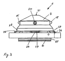
- FIG. 3 is the positioning and tensioning device 1 in a side view shown.
- the main body 2 is rotationally symmetrical and fits exactly to the complementary workpiece or tool holder 30, which in the FIGS. 6 and 7 is shown formed.
- FIG. 3 is also a presence control 36 indicated.
- a small bore 36 is formed, which is flowed through by the hydraulic or pneumatic medium, as long as no workpiece or tool holder 30 is located on the Z-support 26. If the bore 36 is covered with the workpiece holder 30, it can be determined by means of a flow or a pressure switch that no medium flows and that the workpiece has been positioned correctly.
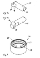
- FIGS. 4a and 4b the locking means 15 is shown by itself in perspective.
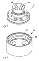
- the piston 4 is shown by itself in perspective.
- the piston 4 has openings 29 into which the locking means 15 can be moved in the radial direction inwards or outwards.
- the control surfaces 16, 18 can be seen. Further matching control surfaces 17 are formed on the clamping cone 4. With the control surfaces 16, 17, 18 it is achieved that the locking means 15 can be forcibly guided in both directions in the piston 4 and in the main body 2.
- FIGS. 6 and 7 two variants of the complementary workpiece or tool holder 30 are shown in perspective.
- more than one positioning and clamping device 1 is required for the positioning of large workpieces.
- Others are not designed for positioning but only for tension or mounting.
- the workpiece holder 30 off FIG. 6 has a centering surface 33 which is continuously conically formed all around.
- the diameter of the conical centering surface 33 is precisely adapted to the diameter of the centering surface 28 of the positioning and clamping device 1. This ensures that a play-free positioning with minimal deformation of the devices to be coupled is possible.
- the diameter of the conical centering surfaces 28,33 is designed so that only a deformation in the elastic region of the material will occur.
- the workpiece or tool holder 30 has on the downwardly directed edge of the centering surface 33 before mounted protective edge 34.
- the protective edge 34 protects the centering surface 33 from dirt and damage.
- the workpiece or tool holder 30 off FIG. 7 has two centering surfaces 35 arranged opposite one another. The workpiece or tool holder 30 off FIG. 7 is thus designed only for centering in the direction of the X or Y axis.
- a clamping system is offered that can be used even at high loads. Because the centering surfaces 28 of the main body 2 are relatively large, and because the locking means 15 operate without balls, the clamping force is distributed on surfaces instead of points. It achieves a precise positioning, which is still reproducible even after a longer life. The holding force of the locking means 15 can be set much greater without risk of damage than in a device with balls.
Landscapes
- Engineering & Computer Science (AREA)
- Mechanical Engineering (AREA)
- Jigs For Machine Tools (AREA)
- Automatic Tool Replacement In Machine Tools (AREA)
- Multi-Process Working Machines And Systems (AREA)
- Gripping On Spindles (AREA)
Claims (17)
- Dispositif de positionnement et de blocage (1) pour des outils et/ou des pièces à travailler, comprenant un corps de base (2), un piston coulissant (4) disposé dans le corps de base (2), un tenon (8) pouvant être relié au piston (4) et au moins un moyen de verrouillage (15) pour le verrouillage du dispositif de positionnement et de blocage par rapport à des porte-pièces ou des porte-outils (30) de forme complémentaire au corps de base (2), dans lequel le corps de base (2) est doté d'un logement cylindrique (3) destiné à recevoir le piston (4), dans lequel un cône de serrage (13) est disposé entre le piston (4) et le tenon (8), dans lequel des surfaces de commande (17, 18) sont formées sur le cône de serrage (13) et sur le piston (4), dans lequel d'autres surfaces de commande (16) coopérant avec les surfaces de commande (17, 18) du cône de serrage (13) et du piston (4) sont formées sur le moyen de verrouillage (15) et dans lequel le moyen de verrouillage (15) est disposé dans le corps de base (2) de façon à pouvoir coulisser radialement, caractérisé en ce que le porte-pièce ou le porte-outil (30) de forme complémentaire est disposé en application extérieure sur le corps de base (2), en ce que le moyen de verrouillage (15) est formé par un coulisseau ou un verrou ayant une section transversale rectangulaire ou ronde, en ce que le moyen de verrouillage (15) est disposé dans un passage (14) du corps de base (2) de façon à pouvoir coulisser radialement, et en ce que les surfaces de commande (16, 17, 18) sont disposées parallèlement l'une à l'autre.
- Dispositif de positionnement et de blocage (1) selon la revendication 1, caractérisé en ce que les surfaces de commande (16) du moyen de verrouillage (15) sont réalisées de façon à coopérer en complémentarité de forme avec les surfaces de commande (17, 18) du piston (4) et du cône de serrage (13), de façon à obtenir une commande forcée en direction radiale vers l'extérieur et vers l'intérieur par rapport à l'axe Z du dispositif de positionnement et de blocage (1).
- Dispositif de positionnement et de blocage (1) selon l'une quelconque des revendications 1 ou 2, caractérisé en ce que le tenon (8) est formé par une vis à épaulement d'ajustement (8) avec une zone de tête (11), une zone d'épaulement (10) et une zone filetée (9).
- Dispositif de positionnement et de blocage (1) selon l'une quelconque des revendications 1 à 3, caractérisé en ce que le cône de serrage (13) présente un alésage central (32) dont le diamètre est plus grand que celui de la zone d'épaulement (10) de la vis à épaulement d'ajustement (8).
- Dispositif de positionnement et de blocage (1) selon l'une quelconque des revendications 1 à 4, caractérisé en ce que le cône de serrage (13) comporte, dans la région du plus grand diamètre de cône, une première surface conique (31) qui forme un angle de moins de 10° par rapport à l'axe Z.
- Dispositif de positionnement et de blocage (1) selon l'une quelconque des revendications 1 à 5,
caractérisé en ce que des appuis en Z (26) sont formés à la périphérie extérieure du corps de base (2). - Dispositif de positionnement et de blocage (1) selon l'une quelconque des revendications 1 à 6, caractérisé en ce que des ouvertures de soufflage (27) sont disposées dans le corps de base (2) à proximité et parallèlement à l'appui en Z (26).
- Dispositif de positionnement et de blocage (1) selon la revendication 7, caractérisé en ce que les ouvertures de soufflage (27) sont légèrement inclinées vers le bas et sont en forme de fentes.
- Dispositif de positionnement et de blocage (1) selon l'une quelconque des revendications 1 à 8, caractérisé en ce que le corps de base (2) présente une surface de centrage conique (28) sur son côté extérieur.
- Dispositif de positionnement et de blocage (1) selon la revendication 9, caractérisé en ce que la surface de centrage conique (28) est concentrique à une surface extérieure cylindrique (61) du corps de base (2).
- Dispositif de positionnement et de blocage (1) selon l'une quelconque des revendications 1 à 10, caractérisé en ce qu'un alésage central traversant (21) jusqu'au logement cylindrique (3) est formé dans le corps de base (2).
- Dispositif de positionnement et de blocage (1) selon la revendication 11, caractérisé en ce qu'un couvercle (22) mobile dans la direction Z et imperdable est disposé dans l'alésage central (21).
- Dispositif de positionnement et de blocage (1) selon l'une quelconque des revendications 3 à 12, caractérisé en ce qu'une rondelle de pression annulaire (12) est disposée entre la tête (11) de la vis à épaulement d'ajustement (8) et le cône de serrage (13).
- Dispositif de positionnement et de blocage (1) selon l'une quelconque des revendications 1 à 13, caractérisé en ce que le couvercle (22) disposé entre la rondelle de pression (12) et une butée (25) du corps de base (2) est mobile dans la direction Z contre une force de ressort.
- Dispositif de positionnement et de blocage (1) selon l'une quelconque des revendications 1 à 14, caractérisé en ce que le porte-pièce ou le porte-outil complémentaire (30) comporte un bord de protection (34).
- Dispositif de positionnement et de blocage (1) selon l'une quelconque des revendications 1 à 15, caractérisé en ce qu'au moins un appui en Z (26) est muni d'un alésage (36) permettant un contrôle de présence.
- Dispositif de positionnement et de blocage (1) selon l'une quelconque des revendications 1 à 16, caractérisé en ce que des conduits destinés à l'air de balayage sont formés dans le corps de base (2) vers le logement cylindrique (3).
Priority Applications (7)
| Application Number | Priority Date | Filing Date | Title |
|---|---|---|---|
| AT05019647T ATE401990T1 (de) | 2005-09-09 | 2005-09-09 | Positionier- und spannvorrichtung für werkzeuge und/oder werkstücke |
| EP05019647A EP1762330B1 (fr) | 2005-09-09 | 2005-09-09 | Dispositif de positionnement et de blocage pour outils et/ou pièces à travailler |
| DE502005004823T DE502005004823D1 (de) | 2005-09-09 | 2005-09-09 | Positionier- und Spannvorrichtung für Werkzeuge und/oder Werkstücke |
| JP2008529480A JP5027133B2 (ja) | 2005-09-09 | 2006-06-10 | 工具用又はワーク用の位置決め・クランプ装置 |
| PCT/EP2006/005586 WO2007031123A1 (fr) | 2005-09-09 | 2006-06-10 | Dispositif de positionnement et de serrage destine a des outils et/ou des pieces |
| US12/065,907 US8061717B2 (en) | 2005-09-09 | 2006-06-10 | Positioning and clamping device for tools and/or workpieces |
| CN2006800321415A CN101253020B (zh) | 2005-09-09 | 2006-06-10 | 用于工具或工件的定位及夹紧装置 |
Applications Claiming Priority (1)
| Application Number | Priority Date | Filing Date | Title |
|---|---|---|---|
| EP05019647A EP1762330B1 (fr) | 2005-09-09 | 2005-09-09 | Dispositif de positionnement et de blocage pour outils et/ou pièces à travailler |
Publications (2)
| Publication Number | Publication Date |
|---|---|
| EP1762330A1 EP1762330A1 (fr) | 2007-03-14 |
| EP1762330B1 true EP1762330B1 (fr) | 2008-07-23 |
Family
ID=35840157
Family Applications (1)
| Application Number | Title | Priority Date | Filing Date |
|---|---|---|---|
| EP05019647A Expired - Lifetime EP1762330B1 (fr) | 2005-09-09 | 2005-09-09 | Dispositif de positionnement et de blocage pour outils et/ou pièces à travailler |
Country Status (7)
| Country | Link |
|---|---|
| US (1) | US8061717B2 (fr) |
| EP (1) | EP1762330B1 (fr) |
| JP (1) | JP5027133B2 (fr) |
| CN (1) | CN101253020B (fr) |
| AT (1) | ATE401990T1 (fr) |
| DE (1) | DE502005004823D1 (fr) |
| WO (1) | WO2007031123A1 (fr) |
Families Citing this family (17)
| Publication number | Priority date | Publication date | Assignee | Title |
|---|---|---|---|---|
| DE502005003100D1 (de) * | 2005-07-09 | 2008-04-17 | 3R Syst Int Ab | Spannvorrichtung für ein Werkzeug oder ein Werkstück |
| CZ19793U1 (cs) | 2009-05-25 | 2009-06-29 | Koran, Spol.S R.O. | Upínací zarízení pro obrábecí stroje |
| DE102010013911B4 (de) * | 2010-04-01 | 2013-07-25 | Schunk Gmbh & Co. Kg Spann- Und Greiftechnik | Spannmodul, insbesondere Nullpunktspannmodul |
| KR20110135587A (ko) * | 2010-06-11 | 2011-12-19 | 두산인프라코어 주식회사 | 문형 머신의 크로스 레일의 클램프 장치 |
| CN101870066B (zh) * | 2010-06-22 | 2011-08-31 | 苏州纽威机床设计研究院有限公司 | 一种带夹紧定位调节装置 |
| CN103302523A (zh) * | 2013-05-21 | 2013-09-18 | 苏州惠瑞自动化集成有限公司 | 一种可限定压力的线材自动夹具 |
| CH708458B1 (de) * | 2013-08-20 | 2017-09-29 | Erowa Ag | Spanneinrichtung. |
| CN103447850A (zh) * | 2013-08-23 | 2013-12-18 | 无锡威孚精密机械制造有限责任公司 | 轴承端盖加工夹具 |
| US20150185104A1 (en) * | 2014-01-02 | 2015-07-02 | George P. Widas, III | System for Calibrating a Tribometer Test Foot |
| CN104440324B (zh) * | 2014-12-29 | 2017-01-25 | 安阳工学院 | 一种差速器壳体内球面粗精锪机床用夹具 |
| CN105014427B (zh) * | 2015-07-16 | 2018-01-09 | 佛山市普拉迪数控科技有限公司 | 一种z型船舶空调梁的工装夹具 |
| CN105382587A (zh) * | 2015-12-18 | 2016-03-09 | 天津天海同步科技有限公司 | 一种自定心铣加工胎具 |
| CN110421395B (zh) * | 2019-09-01 | 2024-05-24 | 苏州速易德工业装备系统有限公司 | 一种高精度柔性零点定位系统 |
| CN110421373B (zh) * | 2019-09-01 | 2024-05-28 | 苏州速易德工业装备系统有限公司 | 一种具有机械锁紧双面约束定位功能的零点定位系统 |
| CN114101746B (zh) * | 2021-12-20 | 2024-02-02 | 陈颖桢 | 一种圆弧工件打孔的加工设备以及其使用方法 |
| CN116037563B (zh) * | 2023-01-13 | 2023-06-06 | 北京航臻科技有限公司 | 用于零点定位系统的除屑装置 |
| CN117564965A (zh) * | 2023-11-30 | 2024-02-20 | 重庆速腾机械制造有限公司 | 一种液压立式夹角装置 |
Family Cites Families (17)
| Publication number | Priority date | Publication date | Assignee | Title |
|---|---|---|---|---|
| US1566370A (en) * | 1925-02-20 | 1925-12-22 | John W Briscoe | Chuck |
| US1873515A (en) * | 1930-11-03 | 1932-08-23 | Charles H Warren | End locating device |
| US2535246A (en) * | 1947-02-10 | 1950-12-26 | Novi Equipment Co | Chuck assembly |
| US3086783A (en) * | 1960-08-17 | 1963-04-23 | United States Steel Corp | Expanding mandrel for machining pipe ends |
| US3978767A (en) * | 1974-07-11 | 1976-09-07 | Joel C. Levin | Automatic center holding fixture for an annular workpiece |
| US4534116A (en) * | 1983-08-26 | 1985-08-13 | Lenzar Optics Corporation | Adapter for boresight telescope |
| DE59705344D1 (de) * | 1996-06-17 | 2001-12-20 | Certa Ag Reinach | Aufspannvorrichtung sowie Einrichtung zum positionsdefinierten Aufspannen eines Werkzeugs oder Werkstücks |
| DE19636375A1 (de) * | 1996-09-09 | 1998-03-12 | Emil Stark | Schnellverschluß für eine Palette unter Späneflug |
| EP1068918B1 (fr) * | 1999-07-14 | 2004-10-20 | Erowa AG | Dispositif de serrage d'une pièce dans une position definie dans une zône de travail d' une machine d'usinage |
| DE10116229A1 (de) * | 2001-04-02 | 2002-10-10 | Mecatool Ag Flawil | Vorrichtung zum lösbaren Halten von Werkstücken an Bearbeitungseinrichtungen |
| DE10117485B4 (de) * | 2001-04-07 | 2004-12-02 | Schunk Gmbh & Co. Kg Fabrik Für Spann- Und Greifwerkzeuge | Spanneinrichtung |
| EP1302278A1 (fr) * | 2001-10-12 | 2003-04-16 | Kabushiki Kaisha Kosmek | Dispositif de serrage |
| ATE297286T1 (de) * | 2002-09-09 | 2005-06-15 | Hermle Berthold Maschf Ag | Festspanneinrichtung zum festspannen zweier teile aneinander |
| JP4260488B2 (ja) * | 2003-01-07 | 2009-04-30 | 株式会社コスメック | 調心駆動機構およびその機構を備えた位置決め装置 |
| JP2004255484A (ja) * | 2003-02-25 | 2004-09-16 | Pascal Engineering Corp | クランプ装置 |
| JP2005040922A (ja) * | 2003-07-25 | 2005-02-17 | Kosmek Ltd | クランプ装置 |
| JP4174453B2 (ja) * | 2004-01-28 | 2008-10-29 | キヤノン株式会社 | ディスクのチャック機構 |
-
2005
- 2005-09-09 DE DE502005004823T patent/DE502005004823D1/de not_active Expired - Lifetime
- 2005-09-09 AT AT05019647T patent/ATE401990T1/de active
- 2005-09-09 EP EP05019647A patent/EP1762330B1/fr not_active Expired - Lifetime
-
2006
- 2006-06-10 US US12/065,907 patent/US8061717B2/en not_active Expired - Fee Related
- 2006-06-10 WO PCT/EP2006/005586 patent/WO2007031123A1/fr not_active Ceased
- 2006-06-10 CN CN2006800321415A patent/CN101253020B/zh not_active Expired - Fee Related
- 2006-06-10 JP JP2008529480A patent/JP5027133B2/ja not_active Expired - Fee Related
Also Published As
| Publication number | Publication date |
|---|---|
| US20080237958A1 (en) | 2008-10-02 |
| ATE401990T1 (de) | 2008-08-15 |
| JP2009506902A (ja) | 2009-02-19 |
| CN101253020B (zh) | 2013-01-09 |
| US8061717B2 (en) | 2011-11-22 |
| CN101253020A (zh) | 2008-08-27 |
| EP1762330A1 (fr) | 2007-03-14 |
| DE502005004823D1 (de) | 2008-09-04 |
| JP5027133B2 (ja) | 2012-09-19 |
| WO2007031123A1 (fr) | 2007-03-22 |
Similar Documents
| Publication | Publication Date | Title |
|---|---|---|
| EP1762330B1 (fr) | Dispositif de positionnement et de blocage pour outils et/ou pièces à travailler | |
| DE60001028T2 (de) | Spannvorrichtung mit Ausrichtfunktion | |
| EP1268123B1 (fr) | Dispositif pour fixer de fa on amovible des pieces a usiner sur des dispositifs d'usinage | |
| EP1344599B1 (fr) | Dispositif de serrage avec mandrin de serrage et tige serrable dans ce mandrin | |
| DE60211932T2 (de) | Klemmvorrichtung | |
| EP1396306B1 (fr) | Dispositif de serrage pour serrer deux pièces l'une à l'autre | |
| EP1321221B1 (fr) | Dispositif de fixation avec mandrin de serrage et porte-pièce pouvant être fixé de façon amovible à celui-ci | |
| AT514431B1 (de) | Spanneinrichtung | |
| DE3880366T2 (de) | Vorrichtung zum loesbaren und wiederholbaren klemmen von zwei elementen. | |
| DE60300111T3 (de) | Vorrichtung zur automatischen Positionierung eines beweglichen Teiles auf einen Referenzteil | |
| EP0608528B1 (fr) | Plaque de serrage à vide | |
| EP1595641A1 (fr) | Dispositif de serrage avec mandrin et palette fixé de façon amovible sur le mandrin. | |
| EP3263274A1 (fr) | Dispositif de serrage et système de serrage | |
| DE102017117037A1 (de) | Fixiervorrichtung | |
| EP2219811B1 (fr) | Dispositif pour serrer un porte-outil sur un mandrin de serrage pouvant être fixé sur une machine d'usinage | |
| DE29722730U1 (de) | Spanneinrichtung zur Fixierung eines Einzugsnippels an einer Aufspannplatte | |
| EP3243599B1 (fr) | Unité de serrage et module de serrage | |
| DE10312192B3 (de) | System-Niederzugspanner | |
| EP1577054B1 (fr) | Cylindre de serrage avec chapeau de fermeture | |
| WO2004091850A1 (fr) | Systeme de serrage comportant une piece d'adaptation | |
| CH703777A2 (de) | Vorrichtung zur positionsdefinierten Aufspannung eines Gegenstandes. | |
| DE9405030U1 (de) | Palettenspannsystem | |
| EP1579948B1 (fr) | Dispositif de serrage | |
| DE20202892U1 (de) | Spanneinrichtung | |
| EP3450090A1 (fr) | Table à coussin d'air |
Legal Events
| Date | Code | Title | Description |
|---|---|---|---|
| PUAI | Public reference made under article 153(3) epc to a published international application that has entered the european phase |
Free format text: ORIGINAL CODE: 0009012 |
|
| AK | Designated contracting states |
Kind code of ref document: A1 Designated state(s): AT BE BG CH CY CZ DE DK EE ES FI FR GB GR HU IE IS IT LI LT LU LV MC NL PL PT RO SE SI SK TR |
|
| AX | Request for extension of the european patent |
Extension state: AL BA HR MK YU |
|
| 17P | Request for examination filed |
Effective date: 20070830 |
|
| 17Q | First examination report despatched |
Effective date: 20071002 |
|
| AKX | Designation fees paid |
Designated state(s): AT BE BG CH CY CZ DE DK EE ES FI FR GB GR HU IE IS IT LI LT LU LV MC NL PL PT RO SE SI SK TR |
|
| GRAP | Despatch of communication of intention to grant a patent |
Free format text: ORIGINAL CODE: EPIDOSNIGR1 |
|
| GRAS | Grant fee paid |
Free format text: ORIGINAL CODE: EPIDOSNIGR3 |
|
| GRAA | (expected) grant |
Free format text: ORIGINAL CODE: 0009210 |
|
| AK | Designated contracting states |
Kind code of ref document: B1 Designated state(s): AT BE BG CH CY CZ DE DK EE ES FI FR GB GR HU IE IS IT LI LT LU LV MC NL PL PT RO SE SI SK TR |
|
| REG | Reference to a national code |
Ref country code: GB Ref legal event code: FG4D Free format text: NOT ENGLISH |
|
| REG | Reference to a national code |
Ref country code: CH Ref legal event code: NV Representative=s name: GEORG FISCHER AG Ref country code: CH Ref legal event code: EP |
|
| REG | Reference to a national code |
Ref country code: IE Ref legal event code: FG4D Free format text: LANGUAGE OF EP DOCUMENT: GERMAN |
|
| REF | Corresponds to: |
Ref document number: 502005004823 Country of ref document: DE Date of ref document: 20080904 Kind code of ref document: P |
|
| NLV1 | Nl: lapsed or annulled due to failure to fulfill the requirements of art. 29p and 29m of the patents act | ||
| PG25 | Lapsed in a contracting state [announced via postgrant information from national office to epo] |
Ref country code: LT Free format text: LAPSE BECAUSE OF FAILURE TO SUBMIT A TRANSLATION OF THE DESCRIPTION OR TO PAY THE FEE WITHIN THE PRESCRIBED TIME-LIMIT Effective date: 20080723 Ref country code: ES Free format text: LAPSE BECAUSE OF FAILURE TO SUBMIT A TRANSLATION OF THE DESCRIPTION OR TO PAY THE FEE WITHIN THE PRESCRIBED TIME-LIMIT Effective date: 20081103 Ref country code: IS Free format text: LAPSE BECAUSE OF FAILURE TO SUBMIT A TRANSLATION OF THE DESCRIPTION OR TO PAY THE FEE WITHIN THE PRESCRIBED TIME-LIMIT Effective date: 20081123 Ref country code: PT Free format text: LAPSE BECAUSE OF FAILURE TO SUBMIT A TRANSLATION OF THE DESCRIPTION OR TO PAY THE FEE WITHIN THE PRESCRIBED TIME-LIMIT Effective date: 20081223 Ref country code: NL Free format text: LAPSE BECAUSE OF FAILURE TO SUBMIT A TRANSLATION OF THE DESCRIPTION OR TO PAY THE FEE WITHIN THE PRESCRIBED TIME-LIMIT Effective date: 20080723 |
|
| PG25 | Lapsed in a contracting state [announced via postgrant information from national office to epo] |
Ref country code: LV Free format text: LAPSE BECAUSE OF FAILURE TO SUBMIT A TRANSLATION OF THE DESCRIPTION OR TO PAY THE FEE WITHIN THE PRESCRIBED TIME-LIMIT Effective date: 20080723 Ref country code: BG Free format text: LAPSE BECAUSE OF FAILURE TO SUBMIT A TRANSLATION OF THE DESCRIPTION OR TO PAY THE FEE WITHIN THE PRESCRIBED TIME-LIMIT Effective date: 20081023 Ref country code: FI Free format text: LAPSE BECAUSE OF FAILURE TO SUBMIT A TRANSLATION OF THE DESCRIPTION OR TO PAY THE FEE WITHIN THE PRESCRIBED TIME-LIMIT Effective date: 20080723 Ref country code: SI Free format text: LAPSE BECAUSE OF FAILURE TO SUBMIT A TRANSLATION OF THE DESCRIPTION OR TO PAY THE FEE WITHIN THE PRESCRIBED TIME-LIMIT Effective date: 20080723 |
|
| REG | Reference to a national code |
Ref country code: IE Ref legal event code: FD4D |
|
| BERE | Be: lapsed |
Owner name: SYSTEM 3R SCHWEIZ A.G. Effective date: 20080930 |
|
| PG25 | Lapsed in a contracting state [announced via postgrant information from national office to epo] |
Ref country code: DK Free format text: LAPSE BECAUSE OF FAILURE TO SUBMIT A TRANSLATION OF THE DESCRIPTION OR TO PAY THE FEE WITHIN THE PRESCRIBED TIME-LIMIT Effective date: 20080723 Ref country code: MC Free format text: LAPSE BECAUSE OF NON-PAYMENT OF DUE FEES Effective date: 20080930 Ref country code: EE Free format text: LAPSE BECAUSE OF FAILURE TO SUBMIT A TRANSLATION OF THE DESCRIPTION OR TO PAY THE FEE WITHIN THE PRESCRIBED TIME-LIMIT Effective date: 20080723 Ref country code: IE Free format text: LAPSE BECAUSE OF FAILURE TO SUBMIT A TRANSLATION OF THE DESCRIPTION OR TO PAY THE FEE WITHIN THE PRESCRIBED TIME-LIMIT Effective date: 20080723 |
|
| PG25 | Lapsed in a contracting state [announced via postgrant information from national office to epo] |
Ref country code: RO Free format text: LAPSE BECAUSE OF FAILURE TO SUBMIT A TRANSLATION OF THE DESCRIPTION OR TO PAY THE FEE WITHIN THE PRESCRIBED TIME-LIMIT Effective date: 20080723 Ref country code: SK Free format text: LAPSE BECAUSE OF FAILURE TO SUBMIT A TRANSLATION OF THE DESCRIPTION OR TO PAY THE FEE WITHIN THE PRESCRIBED TIME-LIMIT Effective date: 20080723 |
|
| PLBE | No opposition filed within time limit |
Free format text: ORIGINAL CODE: 0009261 |
|
| STAA | Information on the status of an ep patent application or granted ep patent |
Free format text: STATUS: NO OPPOSITION FILED WITHIN TIME LIMIT |
|
| 26N | No opposition filed |
Effective date: 20090424 |
|
| PG25 | Lapsed in a contracting state [announced via postgrant information from national office to epo] |
Ref country code: BE Free format text: LAPSE BECAUSE OF NON-PAYMENT OF DUE FEES Effective date: 20080930 |
|
| PG25 | Lapsed in a contracting state [announced via postgrant information from national office to epo] |
Ref country code: SE Free format text: LAPSE BECAUSE OF FAILURE TO SUBMIT A TRANSLATION OF THE DESCRIPTION OR TO PAY THE FEE WITHIN THE PRESCRIBED TIME-LIMIT Effective date: 20081023 |
|
| PG25 | Lapsed in a contracting state [announced via postgrant information from national office to epo] |
Ref country code: PL Free format text: LAPSE BECAUSE OF FAILURE TO SUBMIT A TRANSLATION OF THE DESCRIPTION OR TO PAY THE FEE WITHIN THE PRESCRIBED TIME-LIMIT Effective date: 20080723 |
|
| PG25 | Lapsed in a contracting state [announced via postgrant information from national office to epo] |
Ref country code: LU Free format text: LAPSE BECAUSE OF NON-PAYMENT OF DUE FEES Effective date: 20080909 Ref country code: HU Free format text: LAPSE BECAUSE OF FAILURE TO SUBMIT A TRANSLATION OF THE DESCRIPTION OR TO PAY THE FEE WITHIN THE PRESCRIBED TIME-LIMIT Effective date: 20090124 Ref country code: CY Free format text: LAPSE BECAUSE OF FAILURE TO SUBMIT A TRANSLATION OF THE DESCRIPTION OR TO PAY THE FEE WITHIN THE PRESCRIBED TIME-LIMIT Effective date: 20080723 |
|
| PG25 | Lapsed in a contracting state [announced via postgrant information from national office to epo] |
Ref country code: TR Free format text: LAPSE BECAUSE OF FAILURE TO SUBMIT A TRANSLATION OF THE DESCRIPTION OR TO PAY THE FEE WITHIN THE PRESCRIBED TIME-LIMIT Effective date: 20080723 |
|
| PG25 | Lapsed in a contracting state [announced via postgrant information from national office to epo] |
Ref country code: GR Free format text: LAPSE BECAUSE OF FAILURE TO SUBMIT A TRANSLATION OF THE DESCRIPTION OR TO PAY THE FEE WITHIN THE PRESCRIBED TIME-LIMIT Effective date: 20081024 |
|
| REG | Reference to a national code |
Ref country code: CH Ref legal event code: PUE Owner name: SYSTEM 3R INTERNATIONAL AB, SE Free format text: FORMER OWNER: SYSTEM 3R SCHWEIZ AG, CH |
|
| REG | Reference to a national code |
Ref country code: DE Ref legal event code: R081 Ref document number: 502005004823 Country of ref document: DE Owner name: SYSTEM 3R INTERNATIONAL AB, SE Free format text: FORMER OWNER: SYSTEM 3R SCHWEIZ AG, FLAWIL, CH |
|
| REG | Reference to a national code |
Ref country code: FR Ref legal event code: PLFP Year of fee payment: 12 |
|
| REG | Reference to a national code |
Ref country code: FR Ref legal event code: PLFP Year of fee payment: 13 |
|
| REG | Reference to a national code |
Ref country code: FR Ref legal event code: PLFP Year of fee payment: 14 |
|
| PGFP | Annual fee paid to national office [announced via postgrant information from national office to epo] |
Ref country code: IT Payment date: 20210922 Year of fee payment: 17 Ref country code: AT Payment date: 20210921 Year of fee payment: 17 Ref country code: CH Payment date: 20210920 Year of fee payment: 17 Ref country code: CZ Payment date: 20210909 Year of fee payment: 17 Ref country code: FR Payment date: 20210921 Year of fee payment: 17 |
|
| PGFP | Annual fee paid to national office [announced via postgrant information from national office to epo] |
Ref country code: DE Payment date: 20210920 Year of fee payment: 17 Ref country code: GB Payment date: 20210920 Year of fee payment: 17 |
|
| REG | Reference to a national code |
Ref country code: DE Ref legal event code: R119 Ref document number: 502005004823 Country of ref document: DE |
|
| PG25 | Lapsed in a contracting state [announced via postgrant information from national office to epo] |
Ref country code: CZ Free format text: LAPSE BECAUSE OF NON-PAYMENT OF DUE FEES Effective date: 20220909 |
|
| REG | Reference to a national code |
Ref country code: CH Ref legal event code: PL |
|
| REG | Reference to a national code |
Ref country code: AT Ref legal event code: MM01 Ref document number: 401990 Country of ref document: AT Kind code of ref document: T Effective date: 20220909 |
|
| GBPC | Gb: european patent ceased through non-payment of renewal fee |
Effective date: 20220909 |
|
| PG25 | Lapsed in a contracting state [announced via postgrant information from national office to epo] |
Ref country code: LI Free format text: LAPSE BECAUSE OF NON-PAYMENT OF DUE FEES Effective date: 20220930 Ref country code: FR Free format text: LAPSE BECAUSE OF NON-PAYMENT OF DUE FEES Effective date: 20220930 Ref country code: DE Free format text: LAPSE BECAUSE OF NON-PAYMENT OF DUE FEES Effective date: 20230401 Ref country code: CH Free format text: LAPSE BECAUSE OF NON-PAYMENT OF DUE FEES Effective date: 20220930 Ref country code: AT Free format text: LAPSE BECAUSE OF NON-PAYMENT OF DUE FEES Effective date: 20220909 |
|
| PG25 | Lapsed in a contracting state [announced via postgrant information from national office to epo] |
Ref country code: IT Free format text: LAPSE BECAUSE OF NON-PAYMENT OF DUE FEES Effective date: 20220909 Ref country code: GB Free format text: LAPSE BECAUSE OF NON-PAYMENT OF DUE FEES Effective date: 20220909 |