EP1762433A2 - Ensemble de feux arrière, en particuliers pour véhicules utilitaires - Google Patents
Ensemble de feux arrière, en particuliers pour véhicules utilitaires Download PDFInfo
- Publication number
- EP1762433A2 EP1762433A2 EP06018640A EP06018640A EP1762433A2 EP 1762433 A2 EP1762433 A2 EP 1762433A2 EP 06018640 A EP06018640 A EP 06018640A EP 06018640 A EP06018640 A EP 06018640A EP 1762433 A2 EP1762433 A2 EP 1762433A2
- Authority
- EP
- European Patent Office
- Prior art keywords
- reflector
- housing
- luminaire
- arrangement according
- light
- Prior art date
- Legal status (The legal status is an assumption and is not a legal conclusion. Google has not performed a legal analysis and makes no representation as to the accuracy of the status listed.)
- Withdrawn
Links
- 230000001186 cumulative effect Effects 0.000 claims description 2
- 238000007789 sealing Methods 0.000 description 14
- 238000009434 installation Methods 0.000 description 7
- 230000000295 complement effect Effects 0.000 description 6
- 239000000463 material Substances 0.000 description 6
- 229920002725 thermoplastic elastomer Polymers 0.000 description 4
- 239000000654 additive Substances 0.000 description 3
- 230000000712 assembly Effects 0.000 description 3
- 238000000429 assembly Methods 0.000 description 3
- 239000002131 composite material Substances 0.000 description 3
- 238000001746 injection moulding Methods 0.000 description 3
- 230000001154 acute effect Effects 0.000 description 2
- 238000011161 development Methods 0.000 description 2
- 230000018109 developmental process Effects 0.000 description 2
- 230000010354 integration Effects 0.000 description 2
- 239000003550 marker Substances 0.000 description 2
- 239000004033 plastic Substances 0.000 description 2
- 229920003023 plastic Polymers 0.000 description 2
- 238000009827 uniform distribution Methods 0.000 description 2
- 239000000853 adhesive Substances 0.000 description 1
- 230000001070 adhesive effect Effects 0.000 description 1
- XAGFODPZIPBFFR-UHFFFAOYSA-N aluminium Chemical compound [Al] XAGFODPZIPBFFR-UHFFFAOYSA-N 0.000 description 1
- 229910052782 aluminium Inorganic materials 0.000 description 1
- 238000004873 anchoring Methods 0.000 description 1
- 238000010276 construction Methods 0.000 description 1
- 238000001816 cooling Methods 0.000 description 1
- 230000001419 dependent effect Effects 0.000 description 1
- 230000007613 environmental effect Effects 0.000 description 1
- 230000002349 favourable effect Effects 0.000 description 1
- 210000004907 gland Anatomy 0.000 description 1
- 238000002347 injection Methods 0.000 description 1
- 239000007924 injection Substances 0.000 description 1
- 239000011810 insulating material Substances 0.000 description 1
- 239000000203 mixture Substances 0.000 description 1
- 239000002991 molded plastic Substances 0.000 description 1
- 229920002635 polyurethane Polymers 0.000 description 1
- 239000004814 polyurethane Substances 0.000 description 1
- 239000000243 solution Substances 0.000 description 1
- 230000000007 visual effect Effects 0.000 description 1
Images

Classifications
-
- B—PERFORMING OPERATIONS; TRANSPORTING
- B60—VEHICLES IN GENERAL
- B60Q—ARRANGEMENT OF SIGNALLING OR LIGHTING DEVICES, THE MOUNTING OR SUPPORTING THEREOF OR CIRCUITS THEREFOR, FOR VEHICLES IN GENERAL
- B60Q1/00—Arrangement of optical signalling or lighting devices, the mounting or supporting thereof or circuits therefor
- B60Q1/26—Arrangement of optical signalling or lighting devices, the mounting or supporting thereof or circuits therefor the devices being primarily intended to indicate the vehicle, or parts thereof, or to give signals, to other traffic
- B60Q1/30—Arrangement of optical signalling or lighting devices, the mounting or supporting thereof or circuits therefor the devices being primarily intended to indicate the vehicle, or parts thereof, or to give signals, to other traffic for indicating rear of vehicle, e.g. by means of reflecting surfaces
- B60Q1/301—Arrangement of optical signalling or lighting devices, the mounting or supporting thereof or circuits therefor the devices being primarily intended to indicate the vehicle, or parts thereof, or to give signals, to other traffic for indicating rear of vehicle, e.g. by means of reflecting surfaces by means of surfaces, e.g. metal plate, reflecting the light of an external light source
- B60Q1/3015—Arrangement of optical signalling or lighting devices, the mounting or supporting thereof or circuits therefor the devices being primarily intended to indicate the vehicle, or parts thereof, or to give signals, to other traffic for indicating rear of vehicle, e.g. by means of reflecting surfaces by means of surfaces, e.g. metal plate, reflecting the light of an external light source combined with a lamp
Definitions
- the invention relates to a tail light assembly and a tail light, in particular for commercial vehicles.
- Tail light assemblies for commercial vehicles typically include several light functions, such as driving tail light, brake light, flashing light, reversing light and rear fog light and passive reflectors.
- Vehicle exterior lights on commercial vehicles are typically designed as independent closed luminaire housing and, in contrast to passenger cars with vehicle lights integrated into body openings, attached to the utility vehicle such that the exterior surface of the housing is predominantly or completely exposed to environmental influences.
- a vehicle exterior light in the form of a side marker is z. B. from the DE 203 04 930 U1 known.
- the luminaire housing consists of a pot-shaped transparent lens and a bottom part, which are joined together along a housing joint.
- a light source arrangement is cast in a guided through an opening in the bottom part of the cable in a cavity facing the interior of the housing bottom in polyurethane.
- On the housing joint a plastic material is molded.
- Reflector surfaces are typically formed in side marker lights in the lens such as in the DE 101 59 064 A1 or arranged at the rear lights arrangements as rectangular or triangular reflectors laterally from the luminaire housings of taillights such as in the DE 195 08 86 A ,
- tail lamp assemblies with several in a common pot-shaped housing in separate chambers arranged individual lights are known, which are covered by differently colored for the different lighting functions lenses.
- the invention has for its object to provide an advantageous tail light assembly and a tail light in particular for commercial vehicles.
- the integration of the reflector in the luminaire housing allows a particularly compact and easy-to-assemble construction of the rear lamp assembly.
- the combination of the use of light-emitting diodes as light sources and the integration of the reflector is of particular advantage, as can be arranged by a plurality of light emitting diodes for a light function in a surface next to the reflector and thereby a particularly advantageous utilization of the total surface of the lamp housing or in particular the lens in plan view on the lens in a simple manner is possible.
- the flat design of the light emitting diode array on a flat circuit board and the flat design of a passive reflector complement each other in an advantageous manner and allow a flat design of the common light housing with a particularly small housing depth of advantageously less than 50 mm, especially less than 40 mm, preferably less than 35 mm.
- the reflector is preferably triangular with horizontal base side and upwardly pointing tip, in particular as substantially isosceles Triangle executed.
- the luminaire housing is advantageously designed substantially rectangular and in length and height preferably approximates the dimensions of the reflector in length of the base side and in the amount of the triangular shape, in particular not substantially larger than this.
- orientations the typical position of the tail lamp arrangement is assumed in the case of a vehicle standing on a horizontal standing surface.
- the reflector is advantageously at least one luminaire field, preferably two separate, the reflector horizontally enclosing between them luminous fields formed in triangular reflector and this tightly circumscribed rectangular lamp housing advantageously substantially triangular shaped with downwardly directed tip.
- Reflector surface and luminaire fields complement each other advantageously substantially to a quadrilateral, especially with horizontal upper and lower edges such.
- B preferably to a trapezoid or a rectangle.
- Two luminous fields arranged horizontally on both sides of the reflector can have light-emitting diodes on separate circuit boards. Preferably, however, such separate light fields are arranged on a common board, which runs continuously behind the reflector.
- a shape of one or more LED light fields in addition to the triangular reflector have a non-triangular luminous field contour and / or complement with the reflector to a non-rectangular housing shape.
- the reflector may also have a conventional rectangular shape with horizontal and vertical boundary edges.
- the triangular shape or another surface shape of the luminous fields results for the viewer through an approximately uniform distribution of several Light emitting diodes to a lighting function on the triangular surfaces of a circuit board next to the reflector.
- the light-emitting diodes on the board surfaces can also be distributed differently, but the uniform distribution on the triangular-shaped board surface is particularly advantageous.
- On a luminaire field also several luminaire functions can be realized together.
- the luminaire function of the LEDs in the luminaire housing preferably comprise several of the functions of tail light, flashing light, brake light, rear fog light and reversing light.
- the reflector body may advantageously be supported between the circuit board and the lens.
- the reflector body advantageously covers non-light-emitting further circuit elements on the board.
- the reflector surface is advantageously spaced from the inner surface of the lens.
- the reflector is advantageously colored in itself in the required signal color.
- the lens is preferably colorless transparent.
- the light housing When arranging a triangular reflector in the usual way in a separate housing outside of a light housing of a tail lamp assembly, the light housing is in turn equipped with light emitting diodes as light sources for one, preferably a plurality of light functions.
- the assembly of LEDs as light sources advantageously allows a very small overall depth of the lamp housing, which is not much larger than the overall depth of the separate reflector housing.
- the luminaire housing is advantageously the reflector, which is preferably oriented horizontally in a triangular shape with a base edge and whose side edges extend obliquely to the upwardly pointing tip, horizontally immediately adjacent.
- one of the adjacent side edge of the reflector facing the first side surface of the lamp housing extends substantially parallel to the oblique side edge of the reflector and touches them or Is it at a slight distance of preferably less than 20%, in particular less than 10% of the width of the reflector.
- a reflector facing away from the second side surface of the lamp housing extends in a first advantageous embodiment substantially vertically.
- the second side surface of the lamp housing extends parallel to the first side surface and thus inclined at an angle to the vertical and horizontal.
- An upper and insofar given a lower side surface of the lamp housing advantageously extend substantially horizontally.
- the height of the lamp housing is advantageously at least 75%, in particular at least 85%, preferably at least 95% and at most 130%, in particular at most 115%, preferably at most 105% of the height of the reflector.
- the height of the reflector and the lamp housing is advantageously adapted to the clear height of a U-shaped profile open to the rear as a light carrier and is advantageously at least 80% of this clear height.
- two light housings may be provided in the immediate vicinity of the reflector, which are arranged horizontally opposite each other on both sides of the reflector.
- the two opposite luminaire housing can also be interconnected by a continuous connection behind the reflector.
- the cumulative width of Reflector and one or two arranged in the immediate vicinity of the luminaire housing is advantageously between the simple and 2.5 times the width of the reflector.
- two or more luminaire housings can also be arranged on the same side of the reflector.
- two separate luminaire housing can be arranged one above the other side of the reflector, preferably both superposed luminaire housing have the same height and complement each other to an overall height as indicated above for a single luminaire housing.
- the tail lamp assembly may contain, in an advantageous embodiment, in addition to the lamp housings or instead of one of a plurality of lamp housings in arrangements of the type described another housing or a housing-like body in a model of a lamp housing, which is used as a support of a visual pattern, for , B. a Firmenemblems or the like can serve.
- An advantageous luminaire for a luminaire arrangement with at least one adjacent to a triangular reflector this closely adjacent luminaire housing has an outer contour of its luminaire housing with at least a first horizontal position in installation position and at least one other inclined, ie not perpendicular or parallel to the first edge extending further straight edge on.
- an outer contour is the outline of the lamp housing in projection in the direction of the surface normal of the lens, for commercial vehicle tail lights thus typically in the direction of travel Considering the rounding of corners and / or slight deviations from straight edge curves should be disregarded.
- a first advantageous embodiment of such an outer contour can be given by a triangular shape with in mounting position of the lamp a horizontal, a vertical and an inclined against this edge or a horizontal edge and two preferably symmetrically inclined against these edges, in particular forming an equilateral triangle shape ,
- the contour may be trapezoidal with two in the installed position horizontal parallel edges and at least one inclined against this further straight edge.
- a fourth edge may also be inclined relative to the horizontal edges, in particular to form an isosceles trapezoidal shape, or in a preferred embodiment perpendicular to the two horizontal edges, ie vertically in the installed position.
- the acute angle of a horizontal edge against the inclined straight edge against the horizontal edges is advantageously at least approximately at 60 °.
- a particularly advantageous embodiment provides a contour of the lamp housing in the form of a non-rectangular parallelogram, in particular with angles of 60 ° and 120 ° before.
- the ratio of the lengths of short to long parallelogram edge between 0.4 and 0.5, so that advantageously in a first installation position, the short edges are horizontal and the long edges inclined, the vertical distance of the horizontally extending edges advantageously within the height range described is approximately equal to the height of a triangular reflector or triangle housing to be arranged adjacent.
- the long edges of the parallelogram run horizontally and two identical luminaire housings are arranged one above the other with substantially aligned short edges.
- the two parallelogram lamp housing complement each other to a larger parallelogram with a total height, which in turn is approximately equal to the height of a triangular reflector to be arranged adjacent.
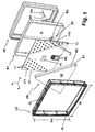
- a two-part housing with a transparent lens LS and a cup-shaped bottom part BT, which are joined together in the x-direction of the drawn with rectangular coordinate system and thereby form a circumferential housing groove GF and enclose an interior on all sides.
- Lens on the one hand and bottom part on the other hand are advantageously made of different materials, especially as injection molded plastic parts.
- the circumferential housing groove GF between the lens and the bottom part advantageously has, in the manner of a labyrinth seal in the cross-section according to FIG. 4, different orientations of opposing joint surfaces.
- the housing joint is completely enclosed on the outside by a sealing body DF, which is applied after the assembly of the lens and the bottom part by injection molding.
- the sealing body advantageously extends from the housing groove along the outer surface of the lens to an edge KL and / or along the outer surface of the bottom part to an edge KB and surrounds this edge (s).
- edge KL or KB nor a groove NL or NB provided, in which the sealing body DF intervenes.
- the luminaire housing advantageously has in the main emission direction x a small housing depth GT of advantageously less than 50 mm, in particular less than 40 mm, preferably less than 35 mm.
- the bottom part has a separate from the housing groove or spaced opening BO for carrying a multi-core cable KA.
- the gap between the cable KA and the opening BO is advantageously sealed by a voltage applied to the outside of the bottom part around the opening BO and the cable sheath of the cable KA further sealing body DK, which is advantageously also molded by injection molding on cable and bottom part
- the sealing body DK of the same material as the sealing body DF along the housing groove GF.
- the sealing body DK at the cable feedthrough and the sealing body DF along the housing joint are preferably connected to one another as a one-piece sealing body.
- the opening BO is arranged in the bottom part in the rear wall surface thereof.
- the position of the opening BO in the rear wall surface of the center of the rear wall is staggered and is preferably closer to the edge of the rear wall surface than at the center of its surface.
- the sealing body DF along the housing joint and / or the sealing body DK on the cable bushing advantageously consist of an injection-moldable thermoplastic elastomer.
- the thermoplastic elastomer may advantageously contain adhesion-promoting additives which are matched to the materials of the lens and the bottom part on the housing joint or cable sheath and bottom part on the cable gland.
- Adhesive additives for thermoplastic elastomers are known per se in great variation.
- the use of a thermoplastic elastomer with adhesion-promoting additives is particularly advantageous for such a sealed luminaire housing, since the permanent elasticity of the cooled after the injection molding sealing body ensures a good seal even with different thermal behavior of the different materials.
- a light source arrangement with two separate luminous fields LF1, LF2 with light sources L1 and L2 is provided on a printed circuit board PLD.
- Each of the two luminous fields advantageously contains a plurality of individual light-emitting diodes as light sources in an arrangement distributed in a planar manner.
- the two light fields are advantageously arranged on a common board.
- a reflector DR is additionally provided, the reflector surface RF has substantially the shape of a triangle, in particular an isosceles, preferably an equilateral triangle with a horizontal base side.
- the reflector DR contained in the example sketched a two-part reflector body RK.
- a terminal block AK via which wires of a connecting cable AK are connected to tracks of the circuit board, and an electronics EL for controlling the LEDs, z. B. for adjusting an independent of the input voltage output voltage, a constant current, etc. provided.
- the advantageously made of insulating material with metallic interconnects printed circuit board LP is advantageously arranged on a heat spreading acting carrier plate WP, for example made of aluminum, which in turn advantageously in turn can be in contact with the plastic material of the bottom part as possible.
- the plate arrangement with carrier plate and circuit board can be held in a defined position in the y-z plane via centering elements ZE formed on the bottom part, which can be advantageous in particular during assembly.
- the printed circuit board ZP essentially has the outline of a rectangle whose horizontal edges (y-direction) are approximately as long as the base side of the triangular surface of the reflector, advantageously at most 50%, in particular at most 25%, preferably at most 15% longer than the base side RL are the triangular area of the reflector.
- the length of the vertical edges (z-direction) corresponds to the printed circuit board, d. H. their height, substantially the height RH of the triangular surface of the reflector, advantageously with a deviation of less than 30%, in particular less than 20%, preferably less than 10%.
- the light fields LF1, LF2 are preferably substantially triangular.
- the lens LS is advantageously transparent colorless.
- the surface of the circuit board can be advantageously colored, preferably, the separate luminaire fields on different shades.
- the cross-section of the luminaire housing with lens LS and bottom part BT is advantageously also substantially rectangular and advantageously in the horizontal y-direction with a length GL by a maximum of 50%, in particular at most 25%, preferably at most 15% greater than the base side of the reflector surface with a length RL and / or in the vertical direction with a height GH by a maximum of 35%, in particular by a maximum of 25%, preferably at most 15% greater than the height RH of the reflector surface.
- the separate luminaire fields are advantageously provided for different lighting functions, even within a luminous field still different lighting functions can be realized.
- a first luminous field LF1 with light sources L1 for the flashing light function and a second luminous field LF2 with light sources L2 for the driving light function and the brake light function can be provided.
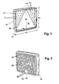
- Fig. 2 illustrates in an oblique view of a composite tail lamp according to Fig. 1, the relative area ratios of the substantially triangular reflector DR, the board luminous surfaces LF1, LF2 with the surfaces distributed light elements L1 and L2 and the entire luminaire housing.
- the width and height of the interior of the lamp housing are substantially equal to the length RL of the lower triangle side and the height RH of the reflector DR and only slightly larger than these dimensions, which over the thickness of the side walls of the lens and bottom part and the sealing body DF and the Determine external dimensions GL and GH of the luminaire housing.
- the contour of the lamp housing with respect to a rectangular shape rounded corners and slightly outwardly curved sides.
- the reflector DR is preferably inserted as a separate component in the form of a reflector body RK between PCB LP and lens and by centering, z.
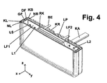
- FIG. 3 shows the tail lamp arrangement according to FIG. 2 from the rear and in particular illustrates the structure of cooling fins KR on the rear wall and the connection of the cable KA via the sealing body DK and the fastening elements BE.
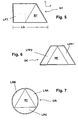
- FIG. 4 shows an oblique view of a half-height horizontally cut rear light according to FIG. 2, from which the position of the individual components in the main emission direction x can be clearly seen.
- Fig. 4 also illustrates the position of the integrated in the rear wall of the bottom part fastening elements BE, in particular threaded head bolts.
- the triangular area of the reflector closely circumscribed rectangular contour of the circuit board or the lamp housing results in a rear light assembly with integrated standard reflector and at the same time small installation dimension and particularly favorable utilization of the cross-sectional area of the lamp housing for various functions.
- FIG. 5 shows an alternative embodiment of a light housing GT with an integrated reflector RF looking in the direction of the surface normal of lens LS or reflector surface RF, ie in the x-direction of FIG. 1.
- Shown are schematically the outlines of the light housing GT and the Reflektors RF and a possible subdivision of the luminous field LFT into different subfields, which can be assigned to different lighting functions.
- the possible subdivision of the luminous field LFT is indicated by broken lines.
- LG of the housing is here typically assume a slightly larger value than for the embodiment of the preceding figures.
- an embodiment is sketched in which are provided within an isosceles-trapezoidal light housing GK horizontally (y-direction) on both sides of the reflector integrated in the housing RF luminous surfaces LFP1 and LFP2 on a preferably continuous behind the reflector board.
- the Luminous surfaces LFP1, LFP2 can in turn be subdivided into different luminaire functions.
- Luminaire fields LRA, LRB and LRC essentially have the shape of circular sections.
- this in the horizontal direction closely adjacent reflector in particular with its own reflector housing GRF is advantageously a oblique edge KRS of the reflector or reflector housing GRF facing and also obliquely and substantially parallel to the edge KRS extending side surface KGZ of the light housing GHT , as outlined in Fig. 8, provided.
- the gap SP between the oblique edge KRS of the reflector or reflector housing GRF and the oblique housing surface KGZ of the luminaire housing GHT is advantageously less than 20%, in particular less than 10%, of the length LRF of the base edge of the reflector housing GRF in the horizontal y direction.
- the horizontally arranged to the reflector luminaire housing GHT advantageously has substantially horizontal upper and lower side surfaces KGO and KGU.
- the height HGL of the luminaire housing is advantageously at least 75%, in particular at least 85% and advantageously at most 130%, in particular at most 115% of the height KRF of the reflector housing GRF and is preferably approximately the same size like the height of the reflector housing.
- the overall length LA of the luminaire arrangement is advantageously between the simple and 2.5 times the length of the base edge KRG of the reflector housing GRF.
- a side face KGA of the light housing GHT facing away from the reflector is essentially vertical.
- Fig. 9 shows an embodiment of a rear lamp assembly again with a viewing direction in the x-direction perpendicular to the lens of a lamp housing or the reflector surface a tail lamp assembly in which laterally next to a reflector housing GRF two separate light housing GHDR and GHDL are arranged, which is substantially triangular with after downwardly directed tip and the triangular surface of the reflector housing GRF to complement a substantially rectangular overall outline.
- the arrangement of the luminous fields LDR in the luminaire housing GHDR and LDL in the luminaire housing GHDL can essentially correspond to the arrangement according to FIG.
- the luminaire housings GHDR and GHDL can be interconnected behind the reflector housing GRF.
- the two luminaire housings have separate light disks above the luminaire fields.
- a tail lamp arrangement in which in addition to a triangular reflector housing GRF a parallelogram-shaped luminaire housing is provided for light-emitting diodes to preferably a plurality of lighting functions.
- a side face KPZ of the luminaire housing GHP facing the reflector runs essentially parallel to the oblique side edge KRS of the reflector housing GRF.
- a side facing away from the reflector side surface KPA of the lamp housing GHP runs in this example sketched also substantially parallel to the oblique side edge KRS of Reflector housing GRF. Indicated by a broken line is the possibility to install also on the horizontally opposite side of the reflector another luminaire housing, for example in turn in parallelogram.
- the individual luminaire housings can also be combined in another combination, for example by symmetrical design of the arrangements according to FIG. 5 or FIG. 8, by arranging two parallelogram luminaire panels or housings on one side of the reflector, also in the form of stacked parallelogram luminous fields or housings long horizontal and short oblique edges.
- the parallelogram luminous fields or luminaire housings of the type of LFP1, LFP2 in FIG. 6 or GHP of FIG. 10 can be combined with the reflector in a particularly advantageous manner in various arrangements.
- the long side of the parallelogram is approximately twice as large as the short side.
- the acute parallelogram angles are equal to the angle between the side and base of the triangular reflector, which is preferably formed on the same side.
- Parts of the surfaces of the lamp housing can also be designed as non-luminous surfaces and z. B. with a pattern, for. B. be printed on a company logo.
- a housing may also include such a pattern instead of a luminaire function.
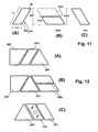
- FIG. 11 is a schematic plan view of the lens, a preferred embodiment of a light housing GPR with parallelogram-shaped outer contour, wherein the corner angles of the parallelogram are preferably at least approximately 60 ° and 120 °.
- the parallelogram-shaped luminaire housing is shown in FIG. 11 (A) in a first installation position with a horizontal course of the short parallelogram edges, in which the height PH1 of the luminaire housing is approximately equal to the height of a triangular reflector to be arranged adjacent.
- Fig. 11 (B) shows the parallelogram-shaped luminaire housing in a second installation position with a horizontal course of the long edges.
- the housing height PH2 is lower here and is preferably between 40% and 50% of the housing height PH1 in the installed position according to FIG. 11 (A).
- a second same housing in the same installation position in the drawn with a broken line position can be arranged in which the facing horizontal edges of the two superimposed luminaire housing facing each other at a small vertical distance at a gap SPH and inclined to the horizontal extending short edges of two superimposed luminaire housing are aligned.
- the two superimposed luminaire housings together form a larger parallelogram with an overall height PHG which is approximately equal to PH1.
- a lamp housing GPL is sketched with mirror-symmetrical parallelogram shape to Fig. 11 (A).
- Two mirror-symmetrical luminaire housings GPR, GPL are generally required if the tail lamp arrangement is to be mirror-symmetrical at least in substantial parts on both sides of the vehicle.
- Fig. 12 to illustrate the particular advantages of a parallelogram lamp housing of FIG. 11 in the use of a compact rear light assembly with triangular reflector some examples of out of several light housings and a triangular reflector composite rear light assemblies are outlined.
- Fig. 12 (A) are on the same side of the triangular reflector to this then a parallelorammförmiges lamp housing GPR and this on the left following a trapezoidal light housing GHT arranged, reflector and both lamp housing have at least approximately equal heights.
- FIG. 12 (B) shows an arrangement with a trapezoidal luminaire housing GHT and two mutually parallelogram-shaped luminaire housings GPR in the second installation position according to FIG. 11 (B).
- Fig. 12 (C) shows an arrangement with a triangular reflector GRF, a subsequent to this trapezoidal housing GDL and to this right following a parallelogram-shaped light housing GPL.
- the housing GDL has a shape inspired by a luminaire housing GPL and is located at the location which could also be assumed by a luminaire housing within the taillight arrangement.
- In the housing GDL is indicated by symbols X, O. X a visually recognizable surface pattern, z. B. a company logo or the like attached.
Landscapes
- Engineering & Computer Science (AREA)
- Mechanical Engineering (AREA)
- Non-Portable Lighting Devices Or Systems Thereof (AREA)
Applications Claiming Priority (2)
| Application Number | Priority Date | Filing Date | Title |
|---|---|---|---|
| DE102005043510 | 2005-09-12 | ||
| DE102006007101A DE102006007101A1 (de) | 2005-09-12 | 2006-02-16 | Heckleuchtenanordnung, insbesondere für Nutzfahrzeuge |
Publications (2)
| Publication Number | Publication Date |
|---|---|
| EP1762433A2 true EP1762433A2 (fr) | 2007-03-14 |
| EP1762433A3 EP1762433A3 (fr) | 2009-05-06 |
Family
ID=37442062
Family Applications (1)
| Application Number | Title | Priority Date | Filing Date |
|---|---|---|---|
| EP06018640A Withdrawn EP1762433A3 (fr) | 2005-09-12 | 2006-09-06 | Ensemble de feux arrière, en particuliers pour véhicules utilitaires |
Country Status (2)
| Country | Link |
|---|---|
| EP (1) | EP1762433A3 (fr) |
| DE (1) | DE102006007101A1 (fr) |
Cited By (6)
| Publication number | Priority date | Publication date | Assignee | Title |
|---|---|---|---|---|
| AU2012254864A1 (en) * | 2012-11-19 | 2014-06-05 | Big Time Auto Parts Mfg. Co., Ltd. | Vehicle warning unit |
| WO2015049264A1 (fr) * | 2013-10-01 | 2015-04-09 | Hella Kgaa Hueck & Co. | Dispositif d'éclairage destiné à des véhicules |
| US9285531B2 (en) | 2008-08-08 | 2016-03-15 | 3M Innovative Properties Company | Lightguide having a viscoelastic layer for managing light |
| EP2103866B1 (fr) * | 2008-03-19 | 2018-04-11 | Honda Motor Co., Ltd. | Phare de véhicule |
| EP3364097A1 (fr) * | 2017-02-21 | 2018-08-22 | Leedarson Lighting Co., Ltd. | Module de luminaire downlight, son procédé de fabrication, et ensemble downlight |
| US10228507B2 (en) | 2008-07-10 | 2019-03-12 | 3M Innovative Properties Company | Light source and optical article including viscoelastic lightguide disposed on a substrate |
Families Citing this family (1)
| Publication number | Priority date | Publication date | Assignee | Title |
|---|---|---|---|---|
| DE102012111688A1 (de) * | 2012-11-30 | 2014-06-05 | Big Time Autoparts Mfg. Co. Ltd. | Warnleuchte |
Citations (6)
| Publication number | Priority date | Publication date | Assignee | Title |
|---|---|---|---|---|
| GB1128730A (en) * | 1966-07-22 | 1968-10-02 | Rau Swf Autozubehoer | Rear light for automotive vehicles |
| DE1950886A1 (de) | 1968-10-22 | 1970-04-23 | M A D Les Montages Et Assembla | Befestigungsmittel fuer rueckwaertige Signale an Fahrzeugen |
| DE10159064A1 (de) | 2001-12-01 | 2003-06-12 | Hella Kg Hueck & Co | Fahrzeugleuchte |
| DE20304930U1 (de) | 2003-02-17 | 2003-08-07 | Aspöck Systems Ges.m.b.H., Peuerbach | Außenleuchte für Fahrzeuge |
| AU2004100738A4 (en) * | 2004-09-02 | 2004-10-28 | Prime Global Brands Ltd. | Tail light assembly |
| DE202005006426U1 (de) * | 2005-04-21 | 2005-07-14 | Aspöck Systems GmbH | Rückleuchte für Anhänger |
Family Cites Families (9)
| Publication number | Priority date | Publication date | Assignee | Title |
|---|---|---|---|---|
| DE8026763U1 (de) * | 1980-10-07 | 1981-02-12 | Westfalia-Werke Franz Knoebel & Soehne Kg, 4840 Rheda-Wiedenbrueck | Rueckleuchten-kombination, insbesondere fuer anhaenger von kraftfahrzeugen |
| FR2707223B1 (fr) * | 1993-07-07 | 1995-09-29 | Valeo Vision | Feu de signalisation perfectionné à diodes électroluminescentes. |
| DE29618562U1 (de) * | 1996-10-24 | 1996-12-12 | Johann & Konen GmbH & Co, 53229 Bonn | Fahrzeugrückleuchte |
| DE29823027U1 (de) * | 1998-12-24 | 1999-03-25 | Johann & Konen GmbH & Co, 53229 Bonn | Fahrzeugrückleuchte |
| DE19946850A1 (de) * | 1999-09-30 | 2001-04-05 | Hella Kg Hueck & Co | Lichttechnische Einrichtung für Fahrzeuge |
| DE10011843B4 (de) * | 2000-03-10 | 2011-03-03 | Volkswagen Ag | Kraftfahrzeugleuchte und Verfahren zum Einstellen verschiedener Signalisierungen |
| DE10036325A1 (de) * | 2000-07-26 | 2002-02-07 | Hella Kg Hueck & Co | Fahrzeugleuchte |
| DE10144478A1 (de) * | 2001-09-10 | 2003-03-27 | Hella Kg Hueck & Co | Leuchte für Fahrzeuge |
| DE20315175U1 (de) * | 2003-10-01 | 2003-12-04 | Fu An Industrial Co., Ltd. | Rücklicht eines Fahrzeugs |
-
2006
- 2006-02-16 DE DE102006007101A patent/DE102006007101A1/de not_active Withdrawn
- 2006-09-06 EP EP06018640A patent/EP1762433A3/fr not_active Withdrawn
Patent Citations (6)
| Publication number | Priority date | Publication date | Assignee | Title |
|---|---|---|---|---|
| GB1128730A (en) * | 1966-07-22 | 1968-10-02 | Rau Swf Autozubehoer | Rear light for automotive vehicles |
| DE1950886A1 (de) | 1968-10-22 | 1970-04-23 | M A D Les Montages Et Assembla | Befestigungsmittel fuer rueckwaertige Signale an Fahrzeugen |
| DE10159064A1 (de) | 2001-12-01 | 2003-06-12 | Hella Kg Hueck & Co | Fahrzeugleuchte |
| DE20304930U1 (de) | 2003-02-17 | 2003-08-07 | Aspöck Systems Ges.m.b.H., Peuerbach | Außenleuchte für Fahrzeuge |
| AU2004100738A4 (en) * | 2004-09-02 | 2004-10-28 | Prime Global Brands Ltd. | Tail light assembly |
| DE202005006426U1 (de) * | 2005-04-21 | 2005-07-14 | Aspöck Systems GmbH | Rückleuchte für Anhänger |
Cited By (7)
| Publication number | Priority date | Publication date | Assignee | Title |
|---|---|---|---|---|
| EP2103866B1 (fr) * | 2008-03-19 | 2018-04-11 | Honda Motor Co., Ltd. | Phare de véhicule |
| US10228507B2 (en) | 2008-07-10 | 2019-03-12 | 3M Innovative Properties Company | Light source and optical article including viscoelastic lightguide disposed on a substrate |
| US9285531B2 (en) | 2008-08-08 | 2016-03-15 | 3M Innovative Properties Company | Lightguide having a viscoelastic layer for managing light |
| AU2012254864A1 (en) * | 2012-11-19 | 2014-06-05 | Big Time Auto Parts Mfg. Co., Ltd. | Vehicle warning unit |
| WO2015049264A1 (fr) * | 2013-10-01 | 2015-04-09 | Hella Kgaa Hueck & Co. | Dispositif d'éclairage destiné à des véhicules |
| US9915406B2 (en) | 2013-10-01 | 2018-03-13 | Hella Kgaa Hueck & Co. | Illumination device for vehicles |
| EP3364097A1 (fr) * | 2017-02-21 | 2018-08-22 | Leedarson Lighting Co., Ltd. | Module de luminaire downlight, son procédé de fabrication, et ensemble downlight |
Also Published As
| Publication number | Publication date |
|---|---|
| EP1762433A3 (fr) | 2009-05-06 |
| DE102006007101A1 (de) | 2007-03-22 |
Similar Documents
| Publication | Publication Date | Title |
|---|---|---|
| DE4101418C2 (de) | Schalterbetätigte Warnleuchte zur Verwendung bei Fahrzeugen | |
| DE4243175B4 (de) | Beleuchtungseinrichtung | |
| DE69308733T2 (de) | Modulare Einheit für Signalleuchte eines Fahrzeugs | |
| EP2095016B1 (fr) | Unité d'éclairage pour phare de véhicule, et phare de véhicule correspondant | |
| EP1852306B1 (fr) | Eclairage doté d'au moins une unité d'élément lumineux pour véhicules, de préférence pour véhicules automobiles | |
| EP2676070B1 (fr) | Luminaire pour façade à diodes électroluminescentes | |
| DE102007043904A1 (de) | Leucht-Vorrichtung | |
| DE102008031262A1 (de) | Beleuchtungseinheit für Fahrzeugscheinwerfer und Fahrzeugscheinwerfer | |
| DE202008007825U1 (de) | Warnleuchte | |
| DE102006001947A1 (de) | Heckleuchtenanordnung | |
| EP1762433A2 (fr) | Ensemble de feux arrière, en particuliers pour véhicules utilitaires | |
| DE102007024421C5 (de) | Gehäuse für ein elektrisches Betriebsmittel | |
| EP0969985B1 (fr) | Feu pour vehicules, notamment feu arriere pour vehicules | |
| DE10315251A1 (de) | Flache Leuchtvorrichtung | |
| DE202015001028U1 (de) | Fahrradschutzblech, versehen mit einer Rücklichtvorrichtung | |
| EP3814172B1 (fr) | Procédé de fabrication d'un module de clignotant ainsi que module de clignotant, système de rétroviseur et véhicule automobile | |
| EP4052963B1 (fr) | Ensemble de pièces pour un module d'éclairage avant | |
| DE102007056270B4 (de) | Beleuchtungseinheit mit einer LED-Lichtquelle | |
| EP1389711B1 (fr) | Lampe à encastrer | |
| DE112017002953T5 (de) | Clip-einheit und kantenmontierte lichtemittierende dioden-(led)-anordnung mit einer clip-einheit | |
| DE102008004483A1 (de) | Flexible Leuchtmittelbaugruppe für Fahrzeugleuchten | |
| WO2021197870A1 (fr) | Module lumineux, phare, véhicule automobile et procédé de production du module lumineux | |
| DE60311193T2 (de) | Signalleuchte und Anzeigevorrichtung die in einem teilweise aus der Kfz-Karosserie bestehendem Gehäuse angeordnet sind | |
| EP0024580A1 (fr) | Lampe de signalisation ou feu de véhicule | |
| DE102020128555A1 (de) | Beleuchtungsvorrichtung für ein Kraftfahrzeug |
Legal Events
| Date | Code | Title | Description |
|---|---|---|---|
| PUAI | Public reference made under article 153(3) epc to a published international application that has entered the european phase |
Free format text: ORIGINAL CODE: 0009012 |
|
| AK | Designated contracting states |
Kind code of ref document: A2 Designated state(s): AT BE BG CH CY CZ DE DK EE ES FI FR GB GR HU IE IS IT LI LT LU LV MC NL PL PT RO SE SI SK TR |
|
| AX | Request for extension of the european patent |
Extension state: AL BA HR MK YU |
|
| RAP1 | Party data changed (applicant data changed or rights of an application transferred) |
Owner name: KOMPLED LIGHTSYSTEMS GMBH |
|
| RAP1 | Party data changed (applicant data changed or rights of an application transferred) |
Owner name: KOMPLED LIGHTSYSTEMS GMBH |
|
| PUAL | Search report despatched |
Free format text: ORIGINAL CODE: 0009013 |
|
| AK | Designated contracting states |
Kind code of ref document: A3 Designated state(s): AT BE BG CH CY CZ DE DK EE ES FI FR GB GR HU IE IS IT LI LT LU LV MC NL PL PT RO SE SI SK TR |
|
| AX | Request for extension of the european patent |
Extension state: AL BA HR MK RS |
|
| 17P | Request for examination filed |
Effective date: 20091106 |
|
| 17Q | First examination report despatched |
Effective date: 20091127 |
|
| AKX | Designation fees paid |
Designated state(s): DE ES FR GB |
|
| STAA | Information on the status of an ep patent application or granted ep patent |
Free format text: STATUS: THE APPLICATION HAS BEEN WITHDRAWN |
|
| 18W | Application withdrawn |
Effective date: 20101014 |