EP1852306B1 - Eclairage doté d'au moins une unité d'élément lumineux pour véhicules, de préférence pour véhicules automobiles - Google Patents
Eclairage doté d'au moins une unité d'élément lumineux pour véhicules, de préférence pour véhicules automobiles Download PDFInfo
- Publication number
- EP1852306B1 EP1852306B1 EP07007657A EP07007657A EP1852306B1 EP 1852306 B1 EP1852306 B1 EP 1852306B1 EP 07007657 A EP07007657 A EP 07007657A EP 07007657 A EP07007657 A EP 07007657A EP 1852306 B1 EP1852306 B1 EP 1852306B1
- Authority
- EP
- European Patent Office
- Prior art keywords
- housing
- lamp
- circuit board
- lamp according
- illuminant
- Prior art date
- Legal status (The legal status is an assumption and is not a legal conclusion. Google has not performed a legal analysis and makes no representation as to the accuracy of the status listed.)
- Active
Links
Images





Classifications
-
- B—PERFORMING OPERATIONS; TRANSPORTING
- B60—VEHICLES IN GENERAL
- B60Q—ARRANGEMENT OF SIGNALLING OR LIGHTING DEVICES, THE MOUNTING OR SUPPORTING THEREOF OR CIRCUITS THEREFOR, FOR VEHICLES IN GENERAL
- B60Q1/00—Arrangement of optical signalling or lighting devices, the mounting or supporting thereof or circuits therefor
- B60Q1/26—Arrangement of optical signalling or lighting devices, the mounting or supporting thereof or circuits therefor the devices being primarily intended to indicate the vehicle, or parts thereof, or to give signals, to other traffic
- B60Q1/2696—Mounting of devices using LEDs
-
- B—PERFORMING OPERATIONS; TRANSPORTING
- B60—VEHICLES IN GENERAL
- B60Q—ARRANGEMENT OF SIGNALLING OR LIGHTING DEVICES, THE MOUNTING OR SUPPORTING THEREOF OR CIRCUITS THEREFOR, FOR VEHICLES IN GENERAL
- B60Q1/00—Arrangement of optical signalling or lighting devices, the mounting or supporting thereof or circuits therefor
- B60Q1/26—Arrangement of optical signalling or lighting devices, the mounting or supporting thereof or circuits therefor the devices being primarily intended to indicate the vehicle, or parts thereof, or to give signals, to other traffic
- B60Q1/2661—Arrangement of optical signalling or lighting devices, the mounting or supporting thereof or circuits therefor the devices being primarily intended to indicate the vehicle, or parts thereof, or to give signals, to other traffic mounted on parts having other functions
- B60Q1/2665—Arrangement of optical signalling or lighting devices, the mounting or supporting thereof or circuits therefor the devices being primarily intended to indicate the vehicle, or parts thereof, or to give signals, to other traffic mounted on parts having other functions on rear-view mirrors
Definitions
- the invention relates to a luminaire having at least one illuminant unit for motor vehicles, according to the preamble of claim 1.
- lamps with illuminants carriers are known in which LEDs are arranged on boards. These boards may have traces on both sides of the board, where the board material is typically resin impregnated paperboard, fiber reinforced resins and / or ceramics. There are printed circuits on the boards which serve for contacting and positioning the LEDs. Furthermore, additional electronic components are often arranged on the boards in addition to the LEDs.
- Out DE 100 20 099 is a generic lamp with at least one lighting unit for motor vehicles known.
- the invention has the object of providing the generic lamp with illuminant unit in such a way that a particularly compact, flat and easy to install light with any shape and smallest number of parts is simple and inexpensive to manufacture.
- the lighting unit is designed so that the narrow side of the board has in the main emission of the lamp.
- the lighting means are arranged substantially along the narrow side of the board and connected to the tracks of the board, resulting in a particularly flat-building Lamp unit leads.
- Such flat-building lighting units can be placed in very small and flat luminaire housing, which in turn leads to a very flat and simple component.
- the lighting unit is equipped, for example, with standardized LEDs as a light source, unlike a planar positioning of the LEDs is not expected to particular difficulties during installation.
- the narrow or front side of the board is easily accessible and can be precisely milled, cut or punched. Since no further optical components have to be positioned very precisely in relatively large distances from one another, a minimal assembly deviation is far less of an effect than with commercially available lamp designs. The assembly effort is greatly reduced and can be performed easily and quickly compared to conventional designs.
- such manufactured luminaires have a durability over the entire service life due to the use of the semiconductor components.
- these lights can be introduced as an insert, for example, in an injection mold.
- the plastic of the entire taillight or of a housing can be integrated into a complete structural unit during the injection process by means of a corresponding cross-linking or at least partially circumscribing the luminaire.
- this concept offers a simplified mounting and mounting in housings or other devices. So aerodynamically favorable versions of the lights / housing are possible through the smaller space and the particularly flat design, or these lights can be arranged in the plane of separation of housings so that these lights barely noticeable and thus can take no disturbing influences on the entire design ,
- FIG. 1 is a lighting unit 2 with the front side of a circuit board 6 arranged bulbs 3 shown.
- the board 6 is a commonly used in the electronics field board, which is usually made of resin-impregnated cardboard, fiber-reinforced resins or ceramic.
- On the top and bottom of the board 6 printed conductors 7 are applied, each having interconnects 7 to the bulbs 3.
- the bulbs 3 are arranged on the front side of the circuit board 6, wherein in each case a contact / Lötfahne 4 of the bulb 3 is with a small gap formation in the immediate vicinity of a printed conductor connection 7.
- These contacts 4 are preferably connected by soldering to the printed conductor connections 7, so that the existing gap between the contacts 4 and the printed conductor connections 7 is safely bridged. Is now applied to the tracks 7 on the top and bottom of the board 6 voltage, a current can flow through the solder joints of the tracks 7 and the contacts, which can let the lamps shine accordingly.
- SMD LEDs Surface Mounted Devices - Light Emitting Diodes
- SMD LEDs are surface mountable components of extremely small size. By using such components that protrude substantially not or only slightly beyond the thickness of the board 6, it is possible to produce very flat and line-shaped / band-shaped lights.
- a light source unit 2 can be combined with further light source units 2 by arranging them in parallel to form a light block.
- FIG. 2 shown, for example, two boards 6 brought close together with their front side soldered bulbs 3. It is advisable that, for example via connection contacts 9, the tracks 7 of the two boards 6 are connected to each other by means of plug or solder contact.
- This constructive measure also limits the thickness expansion of the block-forming illuminant units 2 to the respective thicknesses of the individual circuit boards 6.
- illuminant units 3 with illuminants 3 arranged close to one another or illuminants 3 arranged offset from one another can be used. It can thus be achieved with the smallest structural dimensions, a particularly high light output.
- the light-emitting unit 2 connected to a block has, like a single light source unit 2, only two connection contact points 16, from which in each case one contact point 16 is located on the upper side of the upper circuit board 6 or on the underside of the lower circuit board 6.
- To unwanted contact formations in the block closely adjacent lighting units To prevent the boards 6 may be coated with a protective lacquer or other insulating material.
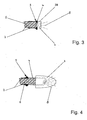
- FIG. 3 shows a schematic section through the lighting unit 2 according to Fig. 1 ,
- the light source 3 in the embodiment, an SMD LED is arranged frontally.
- the contacts / Lötfahnen 4 of the LED 3 protrude up and down slightly beyond the board 6, so that a fillet weld is formed between the contact / Lötfahne 4 and the conductor 7 during soldering.
- Such a connection reliably ensures the contacting of the LED 3 with the conductor 7.
- a solid mechanical connection between the LED 3 and the circuit board 6 is achieved by this connection.
- the contacts / Lötfahnen 4 are mounted on the LED 3, that during assembly of the LED 3 on the front side of the board 6, an air gap 39 is formed between the two components.
- air gaps ensure a clear electrical isolation between the two contacts.
- 39 particularly suitable materials for heat transfer in this air gap may be, for example, thermally conductive pastes or thin metal bands.
- a particularly complex orientation of the LED 3 to the front side of the board 6 is not necessary, since small angular deviations for the emission characteristic of the LED 3 are negligible.
- the boards 6 are usually very precisely cut at an angle of 90 degrees, so that the positioning of an LED 3 can be done only on the slightly protruding contacts / Lötfahen 4.
- FIG. 4 Another variant of LEDs 3 is in FIG. 4 displayed.
- a standardized LED 3 instead of an SMD LED, as in the FIGS. 1 to 3 described, a standardized LED 3 used.
- This standardized LED 3 is considerably larger in terms of its width dimension than the LED 3 described above.
- These LEDs 3 also have no soldering lugs 4, but have long wire-shaped contacts 4. to frontal mounting this LED 3 is pushed with the wire-shaped contacts 4 on the board 6 so that the contacts 4 come into contact with the tracks 7 and can be connected to them by means of soldering.
- the resulting solder joints 5 are also made larger by a larger contact area, which also leads to an increased contact area during the soldering process.
- this contacting surface it makes sense in this variant to use, for example, a laser welding method instead of the soldering method.
- This is advantageous since this connection method can be carried out particularly quickly. There are no heating times and / or cooling and positioning times to consider. Also, in this case the thermal load is lower, since far more material of the contacts 4 and a larger volume of material of the LED 3 is available for receiving heat introduced.
- this design requires more space, but is a cost-effective design and particularly suitable when the LEDs 3 of the lighting unit 2 should protrude, for example, during assembly in reflector openings or other openings.
- FIG. 5 shows a plan view of a curved board 6.
- SMD LEDs arranged as a light source 3 on the front side of the board 6.
- electronic components 10 such as resistors or capacitors, are mounted for the operation of the LEDs.
- These electronic components 10 may be designed in conventional standard design or also as SMD components.
- each four LEDs 3 are connected together to form an LED group 17 wherein an electronic component 10 is assigned to each unit.
- an optimal composition with the largest possible life, the lowest power consumption and minimum space requirements can be achieved, with all traces and all components are mounted on or on the board.
- This compilation yields the finished one Lamp unit 2, which only has to be installed in appropriate housing or recordings and electrically connected.
- the lighting unit 2 can follow the contour of the lamp or the installation space.
- a possible use for this could be a lamp in an exterior mirror housing or in a tail light of a motor vehicle.
- FIG. 6 shows a lamp 1, in which the lighting unit 2 is installed in a lamp housing 13.
- This assembly is a completely finished lamp 1 and can be installed or mounted for example in motor vehicles or for other purposes.
- the luminaire housing 12 consists for example of a transparent plastic and is formed substantially U-shaped.
- the distance and the length of the two U-shaped legs 18 of the lamp housing 12 by the thickness of the board 6 and the width of the light source 3 and the width of the board used 6 and the height of the lamps 3 is determined. Since, for example, the board thickness and the LED width are very similar in the case of SMD LEDs, the free space between the two legs 18 can be very narrow.
- a plurality of printed conductors are applied next to one another on the printed circuit board used, which leads to a wide printed circuit board and thus requires longer legs 18.
- the finished illuminant unit 2 is inserted into this free space of the lamp housing 12 and then closed with a rear wall 13 of the housing.
- the rear wall 13 in FIG. 6 substantially corresponds to the width of the lamp housing 12.
- the parting line 15 between the rear wall 13 and the end faces of the legs 18 of the lamp housing 12 is the contact area between the lamp housing 12 and housing rear wall 13, which by means of a suitable bonding method, for example gluing or welding, the two components tightly interconnected.
- a suitable bonding method for example gluing or welding, the two components tightly interconnected.
- the sealing area projects out connection cables 19 or connection contacts 19.
- At least one spring element 14 is provided in the rear region of the luminaire 1 between the circuit board 6 and the rear wall 13 of the housing. This spring element 14 ensures that the lamp unit always bears under pretension on the inner web side of the U-shaped lamp housing 12.
- This spring element may for example consist of a foam or a spring molding of plastic or metal.
- the luminaire housing 12 is translucent for this purpose at the light exit side.
- FIG. 7 represents a further variant of the embodiment of the lamp housing 12 and housing rear wall 13.
- the legs of the U-shaped lamp housing 12 form the front and rear walls.
- On the end faces of the legs of the housing cover 13 is fixed, which is flush with its edges with the outer sides of the front and rear walls of the lamp housing 12.
- the lighting unit 2 is inserted into the lamp housing 12 and in the same manner as in FIG. 6 described closed.
- Such a design of the lamp housing 12 and the housing cover 13 is advantageous if the board 6, for example, strongly S-shaped wound or the course of the board 6 has other undercuts.
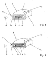
- FIGS. 8 and 9 show lights with illuminant units 2, as essentially below FIG. 6 described.
- an outer optic 20 in the region of Lens 22 is mounted, which is provided on the adjacent to the bulbs 3 transverse web of the lamp housing 12.
- This optic 20 serves to focus the emitted light, to collimate or diffuse it, depending on the optical design.
- the attachment of the optics 20 on the outside can be very interesting for design variants. Also, such luminaires can be well integrated into already structured surfaces, so that the luminaires hardly differ from the surrounding area.
- the optics incorporated as an inner optic 21 In the execution after FIG. 9 is the optics incorporated as an inner optic 21.
- the outside of the lens 22 is smooth and flat, which is particularly advantageous if these lamps 1, for example, just with outer surfaces of housings such as vehicles or vehicle components are used.
- This inner optic 21 has the same possible functions as the outer optic 20 according to FIG. 8 , It is advantageous that the inner optic 21 is less susceptible to soiling and / or damage.
- these tightly closed lights 1 can also be used as so-called inserts in molds for the production of, for example, rear lights of vehicles.
- the lights 1 are integrally connected to the entire tail light, the plastic of the tail light enters into a fixed connection with the light 1 or the light 1 encloses at least partially.
- this lamp 1 can also be used as an insert in other devices.
- FIG. 10 shows an exterior rearview mirror 24, consisting of a mirror housing 26, which is composed of an upper mirror housing part 29 and a lower mirror housing part 28.
- the entire mirror housing 26 is pivotally mounted in or against the direction of travel on a mirror base 25.
- the mirror base 25 has a connection surface 27 a form corresponding to the body region of the motor vehicle with corresponding fastening means.
- the luminaire may consist both of a luminous means carrier 2 and of a plurality of illuminant units 2 which lie close to one another.
- Such flat and small-sized lights 1 are particularly well suited in the separation region of two components, as in the embodiment FIG. 10 shown.
- the lamp 1 in the separation region of the upper mirror housing part 29 and the lower mirror housing part 28 is arranged.
- the mirror housing 26 is a Spiegelglasverstellantrieb 32, with which a mirror glass carrier 31 can be adjusted in a known manner. He carries a mirror glass 30. Since the mirror glass 30 and the Spiegelglasverstellantrieb 32 with a mirror support 33 essentially specify the dimensions of the exterior rearview mirror 24 and the requirements for aerodynamic design must also be met, once again shows that a small installation space is of particular interest.
- the lamp 1 has due to the small dimensions only light weight, whereby the weight of the exterior rearview mirror 24 is increased only slightly by the lamp 1. This in turn has the positive consequence that the mirror housing 26 and the mirror support 33 can be made smaller and lighter. Of course, this reduction in installation space and additional weight also translates into significantly lower production costs.
- a Spiegelglasverstellantrieb 32 In the mirror housing 26 is a Spiegelglasverstellantrieb 32, with which a mirror glass carrier 31 can be adjusted in a known manner. He is wearing a mirror glass 30.
- FIG. 12 shows a possible embodiment, as the light 1 can be fixed and fixed independently of the mirror housing 26 in position.
- many mounting options are conceivable, which can even make a diagonally built-in lamp 1 possible.
- FIGS. 8 and 9 shows appropriate optics 20, 21 provided. These optics 20, 21 are required in order to deflect the light rays emerging from the luminaire in the direction of the main emission direction 11.
- lighting fixture is a lamp holder 37 attached as an additional part of the mirror support 33.
- This lamp holder 37 has a light receptacle 36 at its free, projecting into the mirror housing 26 end.
- the lamp 1 is inserted in the installation position in this lamp holder 36 and secured immovably by means of a fastening means, here a clip 38.
- the illustrated clips 38 protrudes through openings of the lamp holder 36 and the lamp 1, wherein the openings in the lamp 1 may be formed as additional eye-shaped or flange-shaped approaches.
- the clips 38 protrude through the lamp, which of course can only be done in one area without affecting the illuminant carrier 2.
- the lamp 1 can also be done on other components, such as other lights or housing parts.
Landscapes
- Engineering & Computer Science (AREA)
- Mechanical Engineering (AREA)
- Non-Portable Lighting Devices Or Systems Thereof (AREA)
- Arrangement Of Elements, Cooling, Sealing, Or The Like Of Lighting Devices (AREA)
- Fastening Of Light Sources Or Lamp Holders (AREA)
Claims (15)
- Lampe (1) comprenant au moins un module de moyen lumineux (2) pour véhicules automobiles, comprenant au moins une carte et au moins un moyen lumineux (3) fixé sur la carte (6) qui est relié par le biais de contacts (4) à des pistes conductrices (7) de la carte (6), sur le petit côté de laquelle le moyen lumineux (3) est positionné, dans laquelle le module de moyen lumineux (2) est logé dans un logement qui présente un côté de sortie de lumière transparent,
caractérisée en ce que le module de moyen lumineux (2) repose sur le côté de sortie de lumière transparent du logement sous précontrainte. - Lampe selon la revendication 1,
caractérisée en ce que le logement présente un corps de base (12) en forme de U en section transversale dont le côté ouvert est formé de manière étanche avec une paroi de logement (13). - Lampe selon la revendication 1 ou 2,
caractérisée en ce que le logement présente dans la région de sortie de lumière sur le côté externe un élément optique externe (20) et/ou sur le côté interne un élément optique interne (21). - Lampe selon l'une quelconque des revendications 1 à 3,
caractérisée en ce que le moyen lumineux (3) présente un élément optique sur son côté de sortie de lumière. - Lampe selon l'une quelconque des revendications 1 à 4,
caractérisée en ce qu'au moins un élément élastique (14) est prévu pour produire la précontrainte dans le logement. - Lampe selon la revendication 5,
caractérisée en ce que l'élément élastique (14) est prévu sur le côté détourné du moyen lumineux (3) entre la carte (6) et une paroi arrière de logement (13). - Lampe selon la revendication 5 ou 6,
caractérisée en ce que l'élément élastique (14) se compose de mousse. - Lampe selon la revendication 5 ou 6,
caractérisée en ce que l'élément élastique (14) est formé par un élément moulé élastique. - Lampe selon l'une quelconque des revendications 1 à 8,
caractérisée en ce que les pistes conductrices (7) sont logées sur le côté supérieur et/ou sur le côte inférieur de la carte. - Lampe selon l'une quelconque des revendications 1 à 9,
caractérisée en ce que le moyen lumineux (3) est fixé avec le contact (4) à des pistes conductrices (7) du côté supérieur ou du côté inférieur de la carte (6) réalisée avantageusement sous une forme courbée quelconque. - Lampe selon l'une quelconque des revendications 1 à 10,
caractérisée en ce que les contacts (4) sont couchés de manière plane sur le côté supérieur et/ou le côté inférieur de la carte (6) dans la région des pistes conductrices (7). - Lampe selon l'une quelconque des revendications 1 à 11,
caractérisée en ce que les moyens lumineux (3) sont des LED qui sont introduites dans des évidements présents du côté frontal dans la carte (5). - Utilisation de la lampe selon l'une quelconque des revendications 1 à 12 dans un rétroviseur extérieur (24) d'un véhicule automobile.
- Rétroviseur extérieur (24) d'un véhicule automobile comprenant un logement de miroir (26) qui est composé d'une partie de logement de miroir supérieure (29) en dessous d'une partie de logement de miroir inférieure (28), dans lequel la lampe (1) selon l'une quelconque des revendications 1 à 12 est disposée dans une fente de séparation entre les deux parties de logement de miroir (28, 29).
- Rétroviseur extérieur selon la revendication 14, caractérisé en ce qu'un support de lampe (37), qui présente à son extrémité dépassant dans le logement de miroir (26) un logement de lampe (36) dans lequel est maintenue la lampe (1), est monté sur un support de miroir (33).
Applications Claiming Priority (1)
| Application Number | Priority Date | Filing Date | Title |
|---|---|---|---|
| DE102006021973A DE102006021973A1 (de) | 2006-05-03 | 2006-05-03 | Leuchte mit wenigstens einer Leuchtmitteleinheit für Fahrzeuge, vorzugsweise für Kraftfahrzeuge |
Publications (2)
| Publication Number | Publication Date |
|---|---|
| EP1852306A1 EP1852306A1 (fr) | 2007-11-07 |
| EP1852306B1 true EP1852306B1 (fr) | 2010-12-01 |
Family
ID=38235144
Family Applications (1)
| Application Number | Title | Priority Date | Filing Date |
|---|---|---|---|
| EP07007657A Active EP1852306B1 (fr) | 2006-05-03 | 2007-04-14 | Eclairage doté d'au moins une unité d'élément lumineux pour véhicules, de préférence pour véhicules automobiles |
Country Status (4)
| Country | Link |
|---|---|
| US (1) | US8029177B2 (fr) |
| EP (1) | EP1852306B1 (fr) |
| AT (1) | ATE490121T1 (fr) |
| DE (2) | DE102006021973A1 (fr) |
Cited By (1)
| Publication number | Priority date | Publication date | Assignee | Title |
|---|---|---|---|---|
| EP3061587A1 (fr) | 2015-02-24 | 2016-08-31 | SMR Patents S.à.r.l. | Procédé de fabrication d'une lampe pour véhicules et rétroviseur extérieur d'un véhicule doté d'une lampe ainsi fabriquée |
Families Citing this family (9)
| Publication number | Priority date | Publication date | Assignee | Title |
|---|---|---|---|---|
| DE202008007474U1 (de) | 2008-05-30 | 2008-08-07 | Jom Car Parts & Car Hifi Gmbh | Leuchtband mit einem biegeelastischen streifenförmigen Träger |
| DE102010003073B4 (de) | 2010-03-19 | 2013-12-19 | Osram Gmbh | LED-Beleuchtungsvorrichtung |
| EP2377720B1 (fr) * | 2010-04-19 | 2015-06-10 | SMR Patents S.à.r.l. | Dispositif de guide lumineux pour utilisation automobile |
| JP2013530869A (ja) * | 2010-06-22 | 2013-08-01 | アダック プラスティックス,インク. | 選択的照光部分を有するサイドミラーアセンブリ |
| WO2013016652A1 (fr) * | 2011-07-27 | 2013-01-31 | Grote Industries, Llc | Dispositif d'éclairage utilisant un matériau en feuilles actif à la lumière doté d'une diode électroluminescente intégrée, disposée dans une soudure et/ou dans une application à profil bas |
| TW201341717A (zh) * | 2012-04-09 | 2013-10-16 | Foxsemicon Integrated Tech Inc | 燈罩 |
| US9200785B2 (en) * | 2013-08-09 | 2015-12-01 | Kevin Yang | LED light having edge mounted LED's |
| US10041657B2 (en) * | 2016-06-13 | 2018-08-07 | Rebo Lighting & Electronics, Llc | Clip unit and edge mounted light emitting diode (LED) assembly comprising a clip unit |
| DE202019100126U1 (de) * | 2019-01-11 | 2020-04-15 | Zumtobel Lighting Gmbh | Leuchtenanordnung für eine längliche Leuchte |
Family Cites Families (17)
| Publication number | Priority date | Publication date | Assignee | Title |
|---|---|---|---|---|
| US4597033A (en) * | 1983-05-17 | 1986-06-24 | Gulf & Western Manufacturing Co. | Flexible elongated lighting system |
| FR2707223B1 (fr) * | 1993-07-07 | 1995-09-29 | Valeo Vision | Feu de signalisation perfectionné à diodes électroluminescentes. |
| US5561414A (en) * | 1995-02-22 | 1996-10-01 | Yu Hsiang Chiu Enterprise Co., Ltd. | Bicycle warning signal control device |
| JP3260593B2 (ja) * | 1995-06-09 | 2002-02-25 | 株式会社小糸製作所 | 自動車用信号灯 |
| US6203191B1 (en) * | 1998-10-28 | 2001-03-20 | Speculative Incorporated | Method of junction temperature determination and control utilizing heat flow |
| DE10020099A1 (de) * | 2000-04-22 | 2001-10-25 | Hella Kg Hueck & Co | Kraftfahrzeugleuchte |
| ES2168071B1 (es) * | 2000-07-12 | 2003-07-16 | Barros Alejandro Rodriguez | Retrovisor modular con señales multiples intercambiables para vehiculos de 2, 3, 4 o mas ruedas. |
| EP1217291B1 (fr) * | 2000-12-21 | 2007-05-30 | Gamesman Limited | Lampes |
| US6472823B2 (en) * | 2001-03-07 | 2002-10-29 | Star Reach Corporation | LED tubular lighting device and control device |
| CN1505743A (zh) * | 2001-03-21 | 2004-06-16 | 超级影像国际公司 | 具有发光二极管照明设备的挠性电路板 |
| JP3660267B2 (ja) * | 2001-04-13 | 2005-06-15 | 株式会社テーアンテー | 照明灯用具 |
| US6578986B2 (en) * | 2001-06-29 | 2003-06-17 | Permlight Products, Inc. | Modular mounting arrangement and method for light emitting diodes |
| US6578984B2 (en) * | 2001-09-26 | 2003-06-17 | Lite-On Electronics, Inc. | Circuit board indicator |
| US6902308B2 (en) * | 2001-10-09 | 2005-06-07 | Rosstech Signals, Inc. | Illumination system |
| US20050052128A1 (en) * | 2003-09-08 | 2005-03-10 | Polymatech Co. Ltd. | Light emitting electronic component |
| DE102004020493B4 (de) * | 2004-04-26 | 2012-07-12 | Odelo Gmbh | Lichtverteilungsbaugruppe mit einer Vielzahl von Modulen |
| US20060268565A1 (en) * | 2005-05-25 | 2006-11-30 | Haoli Precision Industrial Co., Ltd. | Led lighting device with light diffusing effect |
-
2006
- 2006-05-03 DE DE102006021973A patent/DE102006021973A1/de not_active Withdrawn
-
2007
- 2007-04-14 EP EP07007657A patent/EP1852306B1/fr active Active
- 2007-04-14 AT AT07007657T patent/ATE490121T1/de active
- 2007-04-14 DE DE502007005813T patent/DE502007005813D1/de active Active
- 2007-05-01 US US11/742,824 patent/US8029177B2/en active Active
Cited By (1)
| Publication number | Priority date | Publication date | Assignee | Title |
|---|---|---|---|---|
| EP3061587A1 (fr) | 2015-02-24 | 2016-08-31 | SMR Patents S.à.r.l. | Procédé de fabrication d'une lampe pour véhicules et rétroviseur extérieur d'un véhicule doté d'une lampe ainsi fabriquée |
Also Published As
| Publication number | Publication date |
|---|---|
| DE502007005813D1 (de) | 2011-01-13 |
| ATE490121T1 (de) | 2010-12-15 |
| DE102006021973A1 (de) | 2007-11-15 |
| US20070258253A1 (en) | 2007-11-08 |
| US8029177B2 (en) | 2011-10-04 |
| EP1852306A1 (fr) | 2007-11-07 |
Similar Documents
| Publication | Publication Date | Title |
|---|---|---|
| EP1852306B1 (fr) | Eclairage doté d'au moins une unité d'élément lumineux pour véhicules, de préférence pour véhicules automobiles | |
| EP2095016B1 (fr) | Unité d'éclairage pour phare de véhicule, et phare de véhicule correspondant | |
| EP2291594B1 (fr) | Unité d éclairage pour phare de véhicule et phare de véhicule | |
| EP2317213B1 (fr) | Module de diode luminescente d'un dispositif d'éclairage de véhicule automobile et dispositif d'éclairage de véhicule automobile | |
| EP1970250B1 (fr) | Eclairage pour véhicules, en particulier pour véhicules automobiles | |
| EP2783155B1 (fr) | Dispositif d'éclairage pour véhicule à moteur | |
| EP2428724A1 (fr) | Couplage de lumière optimal pour dispositifs rétroviseurs | |
| EP1099601B1 (fr) | Feu pour véhicule | |
| WO2010000614A1 (fr) | Unité d'éclairage pour un phare de véhicule et phare de véhicule | |
| AT516638A1 (de) | Verfahren zur Herstellung eines Schaltungsträgers und Schaltungsträger | |
| DE102021201873A1 (de) | Reflektor, leuchte, werkzeug, fahrzeug und verfahren zur herstellung einer leuchte | |
| EP2871407B1 (fr) | Système d'émission de lumière et éclairage doté d'un tel système | |
| EP1655174A2 (fr) | Dispositif d'éclairage pour un vehicule | |
| DE102018123968A1 (de) | Stiftförmige Kompaktleuchtstofflampe mit einer Light-Engine aus einem Streifen | |
| DE102022108281B4 (de) | Lichtmodul und Kraftfahrzeugbeleuchtungseinrichtung mit einem solchen Lichtmodul | |
| WO2020229344A1 (fr) | Élément de véhicule, véhicule et procédé | |
| EP2131101A1 (fr) | Lampe | |
| DE10160052A1 (de) | Fahrzeugleuchte | |
| EP1977159B1 (fr) | Éclairage | |
| EP0833761B1 (fr) | Lampe interieure, notamment pour les vehicules automobiles | |
| EP3409439B1 (fr) | Dispositif optique, agencement d'éclairage, phares et procédé | |
| DE10116957A1 (de) | Fahrzeugleuchte | |
| DE102008004483B4 (de) | Fahrzeugleuchte mit flexibler Leuchtmittelbaugruppe | |
| EP2357395B1 (fr) | Unité d'éclairage avec conduit de lumière | |
| DE102006051542B4 (de) | LED-Signalscheinwerfer, insbesondere für Schienenfahrzeuge, sowie LED-Halter für einen solchen Scheinwerfer |
Legal Events
| Date | Code | Title | Description |
|---|---|---|---|
| PUAI | Public reference made under article 153(3) epc to a published international application that has entered the european phase |
Free format text: ORIGINAL CODE: 0009012 |
|
| AK | Designated contracting states |
Kind code of ref document: A1 Designated state(s): AT BE BG CH CY CZ DE DK EE ES FI FR GB GR HU IE IS IT LI LT LU LV MC MT NL PL PT RO SE SI SK TR |
|
| AX | Request for extension of the european patent |
Extension state: AL BA HR MK YU |
|
| RAP1 | Party data changed (applicant data changed or rights of an application transferred) |
Owner name: VISIOCORP PATENTS S.A.R.L. |
|
| 17P | Request for examination filed |
Effective date: 20080416 |
|
| 17Q | First examination report despatched |
Effective date: 20080520 |
|
| AKX | Designation fees paid |
Designated state(s): AT BE BG CH CY CZ DE DK EE ES FI FR GB GR HU IE IS IT LI LT LU LV MC MT NL PL PT RO SE SI SK TR |
|
| 111Z | Information provided on other rights and legal means of execution |
Free format text: AT BE BG CH CY CZ DE DK EE ES FI FR GB GR HU IE IS IT LT LU LV MC MT NL PL PT RO SE SI SK TR Effective date: 20080208 |
|
| RAP1 | Party data changed (applicant data changed or rights of an application transferred) |
Owner name: VISIOCORP PATENTS S.A.R.L. |
|
| RAP1 | Party data changed (applicant data changed or rights of an application transferred) |
Owner name: SMR PATENTS S.A.R.L. |
|
| GRAP | Despatch of communication of intention to grant a patent |
Free format text: ORIGINAL CODE: EPIDOSNIGR1 |
|
| GRAS | Grant fee paid |
Free format text: ORIGINAL CODE: EPIDOSNIGR3 |
|
| GRAA | (expected) grant |
Free format text: ORIGINAL CODE: 0009210 |
|
| AK | Designated contracting states |
Kind code of ref document: B1 Designated state(s): AT BE BG CH CY CZ DE DK EE ES FI FR GB GR HU IE IS IT LI LT LU LV MC MT NL PL PT RO SE SI SK TR |
|
| REG | Reference to a national code |
Ref country code: GB Ref legal event code: FG4D Free format text: NOT ENGLISH |
|
| REG | Reference to a national code |
Ref country code: CH Ref legal event code: EP |
|
| REG | Reference to a national code |
Ref country code: IE Ref legal event code: FG4D |
|
| REF | Corresponds to: |
Ref document number: 502007005813 Country of ref document: DE Date of ref document: 20110113 Kind code of ref document: P |
|
| REG | Reference to a national code |
Ref country code: NL Ref legal event code: VDEP Effective date: 20101201 |
|
| PG25 | Lapsed in a contracting state [announced via postgrant information from national office to epo] |
Ref country code: LT Free format text: LAPSE BECAUSE OF FAILURE TO SUBMIT A TRANSLATION OF THE DESCRIPTION OR TO PAY THE FEE WITHIN THE PRESCRIBED TIME-LIMIT Effective date: 20101201 |
|
| LTIE | Lt: invalidation of european patent or patent extension |
Effective date: 20101201 |
|
| PG25 | Lapsed in a contracting state [announced via postgrant information from national office to epo] |
Ref country code: SE Free format text: LAPSE BECAUSE OF FAILURE TO SUBMIT A TRANSLATION OF THE DESCRIPTION OR TO PAY THE FEE WITHIN THE PRESCRIBED TIME-LIMIT Effective date: 20101201 Ref country code: SI Free format text: LAPSE BECAUSE OF FAILURE TO SUBMIT A TRANSLATION OF THE DESCRIPTION OR TO PAY THE FEE WITHIN THE PRESCRIBED TIME-LIMIT Effective date: 20101201 Ref country code: CY Free format text: LAPSE BECAUSE OF FAILURE TO SUBMIT A TRANSLATION OF THE DESCRIPTION OR TO PAY THE FEE WITHIN THE PRESCRIBED TIME-LIMIT Effective date: 20101201 Ref country code: LV Free format text: LAPSE BECAUSE OF FAILURE TO SUBMIT A TRANSLATION OF THE DESCRIPTION OR TO PAY THE FEE WITHIN THE PRESCRIBED TIME-LIMIT Effective date: 20101201 Ref country code: BG Free format text: LAPSE BECAUSE OF FAILURE TO SUBMIT A TRANSLATION OF THE DESCRIPTION OR TO PAY THE FEE WITHIN THE PRESCRIBED TIME-LIMIT Effective date: 20110301 Ref country code: FI Free format text: LAPSE BECAUSE OF FAILURE TO SUBMIT A TRANSLATION OF THE DESCRIPTION OR TO PAY THE FEE WITHIN THE PRESCRIBED TIME-LIMIT Effective date: 20101201 Ref country code: NL Free format text: LAPSE BECAUSE OF FAILURE TO SUBMIT A TRANSLATION OF THE DESCRIPTION OR TO PAY THE FEE WITHIN THE PRESCRIBED TIME-LIMIT Effective date: 20101201 |
|
| REG | Reference to a national code |
Ref country code: IE Ref legal event code: FD4D |
|
| PG25 | Lapsed in a contracting state [announced via postgrant information from national office to epo] |
Ref country code: GR Free format text: LAPSE BECAUSE OF FAILURE TO SUBMIT A TRANSLATION OF THE DESCRIPTION OR TO PAY THE FEE WITHIN THE PRESCRIBED TIME-LIMIT Effective date: 20110302 |
|
| PG25 | Lapsed in a contracting state [announced via postgrant information from national office to epo] |
Ref country code: ES Free format text: LAPSE BECAUSE OF FAILURE TO SUBMIT A TRANSLATION OF THE DESCRIPTION OR TO PAY THE FEE WITHIN THE PRESCRIBED TIME-LIMIT Effective date: 20110312 Ref country code: PT Free format text: LAPSE BECAUSE OF FAILURE TO SUBMIT A TRANSLATION OF THE DESCRIPTION OR TO PAY THE FEE WITHIN THE PRESCRIBED TIME-LIMIT Effective date: 20110401 Ref country code: IS Free format text: LAPSE BECAUSE OF FAILURE TO SUBMIT A TRANSLATION OF THE DESCRIPTION OR TO PAY THE FEE WITHIN THE PRESCRIBED TIME-LIMIT Effective date: 20110401 Ref country code: CZ Free format text: LAPSE BECAUSE OF FAILURE TO SUBMIT A TRANSLATION OF THE DESCRIPTION OR TO PAY THE FEE WITHIN THE PRESCRIBED TIME-LIMIT Effective date: 20101201 Ref country code: EE Free format text: LAPSE BECAUSE OF FAILURE TO SUBMIT A TRANSLATION OF THE DESCRIPTION OR TO PAY THE FEE WITHIN THE PRESCRIBED TIME-LIMIT Effective date: 20101201 Ref country code: IE Free format text: LAPSE BECAUSE OF FAILURE TO SUBMIT A TRANSLATION OF THE DESCRIPTION OR TO PAY THE FEE WITHIN THE PRESCRIBED TIME-LIMIT Effective date: 20101201 |
|
| PG25 | Lapsed in a contracting state [announced via postgrant information from national office to epo] |
Ref country code: RO Free format text: LAPSE BECAUSE OF FAILURE TO SUBMIT A TRANSLATION OF THE DESCRIPTION OR TO PAY THE FEE WITHIN THE PRESCRIBED TIME-LIMIT Effective date: 20101201 Ref country code: PL Free format text: LAPSE BECAUSE OF FAILURE TO SUBMIT A TRANSLATION OF THE DESCRIPTION OR TO PAY THE FEE WITHIN THE PRESCRIBED TIME-LIMIT Effective date: 20101201 Ref country code: SK Free format text: LAPSE BECAUSE OF FAILURE TO SUBMIT A TRANSLATION OF THE DESCRIPTION OR TO PAY THE FEE WITHIN THE PRESCRIBED TIME-LIMIT Effective date: 20101201 |
|
| PLBE | No opposition filed within time limit |
Free format text: ORIGINAL CODE: 0009261 |
|
| STAA | Information on the status of an ep patent application or granted ep patent |
Free format text: STATUS: NO OPPOSITION FILED WITHIN TIME LIMIT |
|
| BERE | Be: lapsed |
Owner name: SMR PATENTS S.A.R.L. Effective date: 20110430 |
|
| PG25 | Lapsed in a contracting state [announced via postgrant information from national office to epo] |
Ref country code: DK Free format text: LAPSE BECAUSE OF FAILURE TO SUBMIT A TRANSLATION OF THE DESCRIPTION OR TO PAY THE FEE WITHIN THE PRESCRIBED TIME-LIMIT Effective date: 20101201 |
|
| 26N | No opposition filed |
Effective date: 20110902 |
|
| PG25 | Lapsed in a contracting state [announced via postgrant information from national office to epo] |
Ref country code: MC Free format text: LAPSE BECAUSE OF NON-PAYMENT OF DUE FEES Effective date: 20110430 |
|
| REG | Reference to a national code |
Ref country code: CH Ref legal event code: PL |
|
| REG | Reference to a national code |
Ref country code: DE Ref legal event code: R097 Ref document number: 502007005813 Country of ref document: DE Effective date: 20110902 |
|
| PG25 | Lapsed in a contracting state [announced via postgrant information from national office to epo] |
Ref country code: MT Free format text: LAPSE BECAUSE OF FAILURE TO SUBMIT A TRANSLATION OF THE DESCRIPTION OR TO PAY THE FEE WITHIN THE PRESCRIBED TIME-LIMIT Effective date: 20101201 Ref country code: IT Free format text: LAPSE BECAUSE OF FAILURE TO SUBMIT A TRANSLATION OF THE DESCRIPTION OR TO PAY THE FEE WITHIN THE PRESCRIBED TIME-LIMIT Effective date: 20101201 |
|
| PG25 | Lapsed in a contracting state [announced via postgrant information from national office to epo] |
Ref country code: LI Free format text: LAPSE BECAUSE OF NON-PAYMENT OF DUE FEES Effective date: 20110430 Ref country code: CH Free format text: LAPSE BECAUSE OF NON-PAYMENT OF DUE FEES Effective date: 20110430 Ref country code: BE Free format text: LAPSE BECAUSE OF NON-PAYMENT OF DUE FEES Effective date: 20110430 |
|
| REG | Reference to a national code |
Ref country code: DE Ref legal event code: R082 Ref document number: 502007005813 Country of ref document: DE Representative=s name: JONES DAY RECHTSANWAELTE PATENTANWAELTE, DE |
|
| PG25 | Lapsed in a contracting state [announced via postgrant information from national office to epo] |
Ref country code: LU Free format text: LAPSE BECAUSE OF NON-PAYMENT OF DUE FEES Effective date: 20110414 |
|
| REG | Reference to a national code |
Ref country code: AT Ref legal event code: MM01 Ref document number: 490121 Country of ref document: AT Kind code of ref document: T Effective date: 20120414 |
|
| PG25 | Lapsed in a contracting state [announced via postgrant information from national office to epo] |
Ref country code: AT Free format text: LAPSE BECAUSE OF NON-PAYMENT OF DUE FEES Effective date: 20120414 |
|
| PG25 | Lapsed in a contracting state [announced via postgrant information from national office to epo] |
Ref country code: TR Free format text: LAPSE BECAUSE OF FAILURE TO SUBMIT A TRANSLATION OF THE DESCRIPTION OR TO PAY THE FEE WITHIN THE PRESCRIBED TIME-LIMIT Effective date: 20101201 |
|
| PG25 | Lapsed in a contracting state [announced via postgrant information from national office to epo] |
Ref country code: HU Free format text: LAPSE BECAUSE OF FAILURE TO SUBMIT A TRANSLATION OF THE DESCRIPTION OR TO PAY THE FEE WITHIN THE PRESCRIBED TIME-LIMIT Effective date: 20101201 |
|
| REG | Reference to a national code |
Ref country code: FR Ref legal event code: PLFP Year of fee payment: 10 |
|
| REG | Reference to a national code |
Ref country code: FR Ref legal event code: PLFP Year of fee payment: 11 |
|
| REG | Reference to a national code |
Ref country code: FR Ref legal event code: PLFP Year of fee payment: 12 |
|
| REG | Reference to a national code |
Ref country code: DE Ref legal event code: R084 Ref document number: 502007005813 Country of ref document: DE |
|
| P01 | Opt-out of the competence of the unified patent court (upc) registered |
Effective date: 20230616 |
|
| PGFP | Annual fee paid to national office [announced via postgrant information from national office to epo] |
Ref country code: DE Payment date: 20250417 Year of fee payment: 19 |
|
| PGFP | Annual fee paid to national office [announced via postgrant information from national office to epo] |
Ref country code: GB Payment date: 20250423 Year of fee payment: 19 |
|
| PGFP | Annual fee paid to national office [announced via postgrant information from national office to epo] |
Ref country code: FR Payment date: 20250428 Year of fee payment: 19 |