EP1762448B1 - Dispositif pour l'humidification de la vitre d'un véhicule et combinaison de ce dispositif avec une - Google Patents
Dispositif pour l'humidification de la vitre d'un véhicule et combinaison de ce dispositif avec une Download PDFInfo
- Publication number
- EP1762448B1 EP1762448B1 EP06014990A EP06014990A EP1762448B1 EP 1762448 B1 EP1762448 B1 EP 1762448B1 EP 06014990 A EP06014990 A EP 06014990A EP 06014990 A EP06014990 A EP 06014990A EP 1762448 B1 EP1762448 B1 EP 1762448B1
- Authority
- EP
- European Patent Office
- Prior art keywords
- nozzle body
- cavity
- nozzle
- orifice
- motor vehicle
- Prior art date
- Legal status (The legal status is an assumption and is not a legal conclusion. Google has not performed a legal analysis and makes no representation as to the accuracy of the status listed.)
- Not-in-force
Links
Images


Classifications
-
- B—PERFORMING OPERATIONS; TRANSPORTING
- B60—VEHICLES IN GENERAL
- B60S—SERVICING, CLEANING, REPAIRING, SUPPORTING, LIFTING, OR MANOEUVRING OF VEHICLES, NOT OTHERWISE PROVIDED FOR
- B60S1/00—Cleaning of vehicles
- B60S1/02—Cleaning windscreens, windows or optical devices
- B60S1/46—Cleaning windscreens, windows or optical devices using liquid; Windscreen washers
- B60S1/48—Liquid supply therefor
- B60S1/52—Arrangement of nozzles; Liquid spreading means
Definitions
- the present invention relates to a device for moistening a window of a motor vehicle, the device comprising a nozzle body, which receives a spray nozzle and in which a liquid connection is formed, and a fastened to a body part support member to which the nozzle body is pivotally mounted, wherein the Carrier element has a cap and the liquid port on one side of the cap and the spray nozzle is arranged on the other side of the cap. Furthermore, the invention relates to the combination of such a moistening device with a body part of a motor vehicle.
- a nozzle head with a spherical spray nozzle for windscreen washers on motor vehicles is known.
- an inflow pipe is provided, which penetrates a vehicle wall.
- the nozzle head is fixed by means of a resilient clamping disc using a leather disc on the vehicle wall.
- a windscreen washer known, which consists of two mutually pivotable parts. The two parts can be pivoted against each other via a rod which passes through an opening of an engine compartment hood. Further, a part of the windscreen washer device is fastened via peg-shaped fastening elements in a bonnet, wherein the fastening element can simultaneously serve as a conduit for the washing liquid.
- an adjustable windscreen washer known with a nozzle housing which receives two windshield washer nozzles and in which a hose nozzle is formed.
- the nozzle housing is attached via a base plate and a plurality of bearings to two openings of the inner panel of the engine compartment hood.
- a device for moistening a disc of a motor vehicle which has a one-piece nozzle body, in which a nozzle insert is arranged, which receives a spray nozzle.
- On the nozzle body is a liquid connection educated.
- the nozzle body is held by two nozzle holder parts.
- the one nozzle holder part is rotationally fixed, preferably in one piece, formed with the nozzle body and rests on one side on an edge of an opening of a vehicle part.
- the humidifier should be easily mounted and connected in the engine compartment hood. Further, the moistening device protruding from the engine hood may result in increased wind noise and vehicle washing problems with conventional car washes.
- the stationary carrier element is designed as a cover shell arranged above the pivotable nozzle part with an internal cavity, and the nozzle part is arranged inside this cavity.
- the moistening device is characterized in that the carrier element has a diaphragm which extends away from the cover cap at a certain angle.
- the diaphragm also has at least one opening which is arranged such that a liquid jet emerging from the spray nozzle passes through the opening.
- the side of the moistening device, on which the fluid port is located can be sealed in a mounting cavity, so that, for example, no gases can pass from the engine compartment to the fluid port.
- not all parts of the nozzle body are enclosed by a covering shell, so that they remain accessible for mounting the moistening device.
- the diaphragm is provided, which is inexpensive and therefore cost-effective to the respective receiving locations and forms of the motor vehicle can be adjusted.
- the moistening device according to the invention is thus inexpensive to produce and adaptable to different vehicle types, since the nozzle body can be used unchanged in different types of vehicles and only the support element must be adjusted.
- the covering cap of the carrier element is plate-shaped. It has a recess for the passage of the nozzle body. Furthermore, the nozzle body preferably has an adjusting device for adjusting the pivoting angle of the nozzle body, which can be actuated through the opening of the diaphragm or through a further opening in the diaphragm. In this way, the angle of the liquid jet, which exits through the spray nozzle during operation of the moistening device, is easily adjustable from the outside.
- a holder for pivotally receiving the nozzle body adjoins the cap of the support member, wherein the end of the nozzle body, wherein the spray nozzle is arranged, is received by the opening of the aperture with so much play that the Nozzle body can be pivoted about a certain pivot angle for adjusting the liquid jet angle.
- the inventive combination of a body part of a motor vehicle with the moistening device described above is characterized in that the body part has a cavity with an opening that the cap of the carrier element of the moistening device is placed on the opening of the cavity, that the fluid port is located within the cavity and the spray nozzle outside the cavity.
- the body part may in particular be an engine compartment hood of the motor vehicle, wherein the cap closes off the opening of the cavity in a gastight manner.
- the cavity is formed in particular between an outer panel and an inner panel of the engine compartment hood, wherein the opening of the cavity is formed in the inner panel of the engine compartment hood.
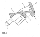
- the moistening device consists essentially of two parts, namely a nozzle body 1 and a carrier element 4.
- the nozzle body 1 is attached to the support member 4 that it is pivotable in a small angular range.
- the nozzle body 1 is a plastic part, in which at one end a liquid connection 3, e.g. a connecting piece, is formed. At the other end of the nozzle body 1, this receives a spray nozzle.
- the spray nozzle 2 may be formed in a separate part. However, it can also be integrally formed in the nozzle body 1.
- a liquid channel extends from the terminal 3 to the outlet opening of the spray nozzle 2.
- a fastening device is provided, through which the nozzle body 1 in a holder 17 of the support member 4 about the axis 11 can be pivotally mounted.
- the holder 17 for the pivotal receptacle of the nozzle body 1 is formed approximately in the center of the cap.
- the carrier element 4 consists essentially of a plate-shaped cap 4 and a diaphragm 6, which extends at an angle ⁇ of the cap 5 away.
- the ⁇ angle between the cap 5 and the diaphragm 6 is an acute angle. It is preferably in a range between 70 ° and 80 °. In the present embodiment, the angle ⁇ is about 77 °.
- the cover 5 of the support member 4 is a recess, in particular an opening, formed for the passage of the nozzle body.
- the nozzle body 1 is thus on the carrier element 4th attached, that the liquid port 3 is located on one side of the cap 5, the nozzle body 1 extends from the liquid port 3, starting through the recess or opening of the cap 5 and the part of the nozzle body 1, which receives the spray nozzle 2, on the other side of the cap 5 is arranged.
- the diaphragm 6 has an opening 8 in which the front end of the nozzle body 1 is flush. At this end of the nozzle body 1, the spray nozzle 2 is arranged so that a liquid jet, which exits at the spray nozzle 2, can be injected through the opening 8 of the diaphragm 6 onto the window of a motor vehicle.
- the diaphragm 6 has a further opening 9, in which an adjusting device 10 is arranged for adjusting the pivot angle of the nozzle body 1.
- the adjusting device 10 is a screw which is coupled to the nozzle body 1 and the carrier element 4 such that when the screw is rotated, the angle between the nozzle body 1 and the carrier element 4 changes. In order for such a pivoting of the nozzle body 1 is possible, so much play is provided between the front end of the nozzle body 1 and the opening 8 of the diaphragm 6, that the nozzle body 1 can be pivoted by the desired angular range.
- Fig. 6 shows the combination of a body part of a motor vehicle and the above with reference to the Fig. 1 to 5 explained device for moistening a disc of the motor vehicle.
- the engine compartment hood of the vehicle consists, at least in the section which is adjacent to the windshield, of an outer panel 14, which is visible from the outside, and of an inner panel 13, which is visible only when the engine compartment hood is open. Between the outer panel 14 and the inner panel 13, a cavity 16 is formed. The cavity 16 is accessible via an opening which is formed in the inner panel 13. Through this opening, the moistening device is inserted so that the opening is gas-tight and opaque covered or sealed by the cap 5 of the support member 4 of the moistening device.
- a water hose 12 is also introduced, which emanates from a spray water reservoir.
- the end of the tube 12 is slipped over the liquid port 3 of the nozzle body 1 and fixed thereto.
- the opening in the inner panel 13 is therefore so large that you can reach into the cavity 16 with the fingers to the end of the Tube 12 to take.
- the cover cap 5 by means of projections 7 (see FIGS. 2 and 3 ) clipped into the opening of the inner panel 13. After that, no gases can escape from the engine compartment into the cavity 16. In addition, you can not see the connections of the humidifier with the engine compartment hood open.
- a further vehicle part is provided below the inner panel 13 of the engine compartment hood.
- this is the cover 15 of the water box.
- the diaphragm 6 of the carrier element 4 of the moistening device is designed so that it extends from the end of the cap 5 in the direction of the water box cover 15 and ends immediately in front of this cover 15.
- the panel 6 thus closes the gap between the inner panel 13 and the water box cover 15. Looking from the direction of the windshield of the motor vehicle in the area under the front edge of the engine compartment hood, only the front part of the inner panel 13, the diaphragm 6 and a part of the water tank cover 15 can be seen.
Landscapes
- Engineering & Computer Science (AREA)
- Water Supply & Treatment (AREA)
- Mechanical Engineering (AREA)
- Air-Conditioning For Vehicles (AREA)
- Nozzles (AREA)
- Rear-View Mirror Devices That Are Mounted On The Exterior Of The Vehicle (AREA)
- Superstructure Of Vehicle (AREA)
- Window Of Vehicle (AREA)
Claims (7)
- Dispositif pour l'humidification d'une vitre de véhicule automobile, le dispositif comportant un corps de buse (1) :- logeant une buse d'injection (2) ;- au niveau duquel un raccord de liquide (3) est réalisé;- comportant un élément de support (4) :- au niveau duquel le corps de buse (1) peut être fixé de façon pivotante;- qui comporte une calotte de revêtement (5) ;- le raccord de liquide (3) étant disposé sur un côté de celle-ci et la buse d'injection (2) sur l'autre côté ;- comportant un diaphragme (6) :- s'écartant selon l'angle (α) par rapport à la calotte de revêtement (5) ;- comportant au moins une ouverture (8) :- qui est disposée de telle sorte qu'un jet de liquide sortant de la buse d'injection (2) traverse l'ouverture (8) ; et- pouvant être fixée à une partie de carrosserie.
- Dispositif selon la revendication 1, caractérisé en ce que la calotte de revêtement (5) de l'élément de support (4) prend une forme de plaque et possède un évidement pour le passage du corps de buse (1).
- Dispositif selon l'une quelconque des revendications précédentes, caractérisé en ce que le corps de buse (1) comporte un dispositif de réglage (10) pour régler l'angle de pivotement du corps de buse (1), ledit dispositif pouvant être actionné à travers l'ouverture du diaphragme (6) ou à travers une autre ouverture (9) prévue dans le diaphragme (6).
- Dispositif selon la revendication 2 ou 3, caractérisé en ce qu'une fixation (17) est raccordée à la calotte de revêtement (5) de l'élément de support (4) pour loger de façon pivotante le corps de buse (1) et que l'extrémité du corps de buse (1) dans laquelle la buse d'injection (2) est disposée est logée avec un jeu tel par rapport à l'ouverture (9) du diaphragme (6) que le corps de buse (1) peut pivoter d'un angle de pivotement défini en vue de régler l'angle du jet de liquide.
- Combinaison d'une partie de carrosserie (13, 14) de véhicule automobile et d'un dispositif pour l'humidification d'une vitre de véhicule automobile selon l'une quelconque des revendications précédentes, caractérisée en ce que la partie de carrosserie (13, 14) comporte un espace creux (16) doté d'une ouverture et que la calotte de revêtement (5) de l'élément de support (4) du dispositif d'humidification est placé de telle sorte sur l'ouverture de l'espace creux (16) que le raccord de liquide (3) se trouve à l'intérieur de l'espace creux (16) et que la buse d'injection (2) se trouve à l'extérieur de l'espace creux (16).
- Combinaison selon la revendication 5, caractérisée en ce que la partie de carrosserie (13, 14) est un capot de compartiment-moteur du véhicule automobile et que la calotte de revêtement (5) ferme l'ouverture de l'espace creux (16) de façon étanche aux gaz.
- Combinaison selon la revendication 6, caractérisée en ce que l'espace creux (16) est formé entre une tôle extérieure (14) et une tôle intérieure (13) du capot de compartiment-moteur et que l'ouverture de l'espace creux (16) est réalisée dans la tôle intérieure (13) du capot de compartiment-moteur.
Applications Claiming Priority (1)
| Application Number | Priority Date | Filing Date | Title |
|---|---|---|---|
| DE102005043080A DE102005043080A1 (de) | 2005-09-10 | 2005-09-10 | Vorrichtung zum Befeuchten einer Scheibe eines Kraftfahrzeugs und Kombination einer solchen mit einem Karosserieteil |
Publications (3)
| Publication Number | Publication Date |
|---|---|
| EP1762448A2 EP1762448A2 (fr) | 2007-03-14 |
| EP1762448A3 EP1762448A3 (fr) | 2008-11-12 |
| EP1762448B1 true EP1762448B1 (fr) | 2011-05-11 |
Family
ID=37402657
Family Applications (1)
| Application Number | Title | Priority Date | Filing Date |
|---|---|---|---|
| EP06014990A Not-in-force EP1762448B1 (fr) | 2005-09-10 | 2006-07-19 | Dispositif pour l'humidification de la vitre d'un véhicule et combinaison de ce dispositif avec une |
Country Status (3)
| Country | Link |
|---|---|
| EP (1) | EP1762448B1 (fr) |
| AT (1) | ATE508915T1 (fr) |
| DE (1) | DE102005043080A1 (fr) |
Family Cites Families (9)
| Publication number | Priority date | Publication date | Assignee | Title |
|---|---|---|---|---|
| DE1838995U (de) * | 1959-03-10 | 1961-10-05 | Westfaelische Metall Ind K G H | Duesenkopf mit mindestens einer kugelfoermigen spritzduese fuer scheibenwaschanlagen an kraftfahrzeugen. |
| DE3925800A1 (de) * | 1989-08-04 | 1991-02-07 | Bayerische Motoren Werke Ag | Scheibenwaschvorrichtung |
| DE4305245A1 (de) * | 1993-02-20 | 1994-08-25 | Bayerische Motoren Werke Ag | Einstellbare Scheibenwaschvorrichtung |
| DE19641460C2 (de) | 1996-10-09 | 2002-08-08 | Volkswagen Ag | Vorrichtung zur Befeuchtung einer Scheibe eines Kraftfahrzeuges |
| DE19652083C2 (de) * | 1996-12-14 | 2002-07-11 | Siemens Ag | Zur Befestigung in einem Kraftfahrzeug vorgesehener Düsenstock |
| US6467701B2 (en) * | 1997-09-26 | 2002-10-22 | Mannesmann Vdo Ag | Shield cleaning system |
| DE19746059C2 (de) * | 1997-10-17 | 2000-01-20 | Daimler Chrysler Ag | Scheibenwaschvorrichtung |
| JP3901873B2 (ja) * | 1999-05-27 | 2007-04-04 | 株式会社小糸製作所 | ヘッドランプクリーナ |
| DE10303410B4 (de) * | 2003-01-29 | 2013-10-31 | Volkswagen Ag | Kombination einer Scheibenwascheinrichtung mit einem Fahrzeugteil |
-
2005
- 2005-09-10 DE DE102005043080A patent/DE102005043080A1/de not_active Withdrawn
-
2006
- 2006-07-19 AT AT06014990T patent/ATE508915T1/de active
- 2006-07-19 EP EP06014990A patent/EP1762448B1/fr not_active Not-in-force
Also Published As
| Publication number | Publication date |
|---|---|
| ATE508915T1 (de) | 2011-05-15 |
| EP1762448A2 (fr) | 2007-03-14 |
| EP1762448A3 (fr) | 2008-11-12 |
| DE102005043080A1 (de) | 2007-03-15 |
Similar Documents
| Publication | Publication Date | Title |
|---|---|---|
| DE102007060252B4 (de) | Wischerblatt und Fahrzeugwischer | |
| DE69836997T2 (de) | Konstruktion eines öffnungsfähigen Fahrzeugdaches | |
| EP0028370A1 (fr) | Véhicule automobile comprenant un miroir additionnel supprimant l'angle mort | |
| DE4338685C1 (de) | Fahrzeugkarosserie | |
| EP1658209A1 (fr) | Dispositif a fixer dans un vehicule automobile et destine au nettoyage d'une vitre ou d'un verre diffusant | |
| EP1549535B1 (fr) | Dispositif de lavage d'une vitre de vehicule automobile | |
| DE102010005812A1 (de) | Instrumententafel eines Kraftfahrzeuges mit einem Ablagefach | |
| DE2851178A1 (de) | Fahrzeugbelueftungsvorrichtung | |
| EP1978259A2 (fr) | Amortisseur de bruit destiné à l'utilisation sur un compresseur | |
| DE3818666A1 (de) | Luftkanal fuer ein kraftfahrzeug | |
| DE9100514U1 (de) | Luftführungselement | |
| DE102018215147A1 (de) | Blendenbaugruppe für ein fahrzeug | |
| EP1762448A2 (fr) | Dispositif pour l'humidification de la vitre d'un véhicule et combinaison de ce dispositif avec une | |
| DE4034851A1 (de) | Vorrichtung zur geraeusch- und schwingungsminderung an schiebedachoeffnungen von kraftfahrzeugen | |
| DE3512312A1 (de) | Windabweiseranordnung | |
| DE4305245A1 (de) | Einstellbare Scheibenwaschvorrichtung | |
| DE102020133652A1 (de) | Luftleitvorrichtung für einen Innenraum eines Kraftfahrzeugs | |
| DE10217490B4 (de) | Kraftfahrzeug mit wenigstens einer Bremsleuchte in einem oberen Heckscheiben-Randbereich | |
| DE102005045410A1 (de) | Scheibenwischeranlage für ein Fahrzeug mit wenigstens einer waschflüssigkeitsführenden Wischerwelle | |
| DE4138613C1 (en) | Ventilator in motor vehicle - has rectangular frame holding set of air-deflecting lamellae | |
| DE10011840B4 (de) | Scheibenwascheinrichtung für eine Kraftfahrzeugfrontscheibe | |
| EP2125453B1 (fr) | Ensemble boitier d'un systeme d'essuie-glace de vehicule | |
| DE2823528C2 (de) | Belüftungssystem für den Fahrgastraum eines Kraftfahrzeuges | |
| DE102004016991B4 (de) | Einrichtung zur Reinigung einer Scheibe eines Kraftfahrzeuges | |
| DE102013009733B4 (de) | Entwässerungsanordnung an einem Kraftfahrzeug und Kraftfahrzeug dazu |
Legal Events
| Date | Code | Title | Description |
|---|---|---|---|
| PUAI | Public reference made under article 153(3) epc to a published international application that has entered the european phase |
Free format text: ORIGINAL CODE: 0009012 |
|
| AK | Designated contracting states |
Kind code of ref document: A2 Designated state(s): AT BE BG CH CY CZ DE DK EE ES FI FR GB GR HU IE IS IT LI LT LU LV MC NL PL PT RO SE SI SK TR |
|
| AX | Request for extension of the european patent |
Extension state: AL BA HR MK YU |
|
| PUAL | Search report despatched |
Free format text: ORIGINAL CODE: 0009013 |
|
| AK | Designated contracting states |
Kind code of ref document: A3 Designated state(s): AT BE BG CH CY CZ DE DK EE ES FI FR GB GR HU IE IS IT LI LT LU LV MC NL PL PT RO SE SI SK TR |
|
| AX | Request for extension of the european patent |
Extension state: AL BA HR MK RS |
|
| 17P | Request for examination filed |
Effective date: 20090512 |
|
| AKX | Designation fees paid |
Designated state(s): AT BE BG CH CY CZ DE DK EE ES FI FR GB GR HU IE IS IT LI LT LU LV MC NL PL PT RO SE SI SK TR |
|
| 17Q | First examination report despatched |
Effective date: 20100119 |
|
| GRAP | Despatch of communication of intention to grant a patent |
Free format text: ORIGINAL CODE: EPIDOSNIGR1 |
|
| GRAS | Grant fee paid |
Free format text: ORIGINAL CODE: EPIDOSNIGR3 |
|
| GRAA | (expected) grant |
Free format text: ORIGINAL CODE: 0009210 |
|
| AK | Designated contracting states |
Kind code of ref document: B1 Designated state(s): AT BE BG CH CY CZ DE DK EE ES FI FR GB GR HU IE IS IT LI LT LU LV MC NL PL PT RO SE SI SK TR |
|
| REG | Reference to a national code |
Ref country code: GB Ref legal event code: FG4D Free format text: NOT ENGLISH |
|
| REG | Reference to a national code |
Ref country code: CH Ref legal event code: EP |
|
| REG | Reference to a national code |
Ref country code: IE Ref legal event code: FG4D |
|
| REG | Reference to a national code |
Ref country code: DE Ref legal event code: R096 Ref document number: 502006009465 Country of ref document: DE Effective date: 20110622 |
|
| REG | Reference to a national code |
Ref country code: NL Ref legal event code: VDEP Effective date: 20110511 |
|
| PG25 | Lapsed in a contracting state [announced via postgrant information from national office to epo] |
Ref country code: LT Free format text: LAPSE BECAUSE OF FAILURE TO SUBMIT A TRANSLATION OF THE DESCRIPTION OR TO PAY THE FEE WITHIN THE PRESCRIBED TIME-LIMIT Effective date: 20110511 Ref country code: SE Free format text: LAPSE BECAUSE OF FAILURE TO SUBMIT A TRANSLATION OF THE DESCRIPTION OR TO PAY THE FEE WITHIN THE PRESCRIBED TIME-LIMIT Effective date: 20110511 Ref country code: PT Free format text: LAPSE BECAUSE OF FAILURE TO SUBMIT A TRANSLATION OF THE DESCRIPTION OR TO PAY THE FEE WITHIN THE PRESCRIBED TIME-LIMIT Effective date: 20110912 |
|
| PG25 | Lapsed in a contracting state [announced via postgrant information from national office to epo] |
Ref country code: IS Free format text: LAPSE BECAUSE OF FAILURE TO SUBMIT A TRANSLATION OF THE DESCRIPTION OR TO PAY THE FEE WITHIN THE PRESCRIBED TIME-LIMIT Effective date: 20110911 Ref country code: SI Free format text: LAPSE BECAUSE OF FAILURE TO SUBMIT A TRANSLATION OF THE DESCRIPTION OR TO PAY THE FEE WITHIN THE PRESCRIBED TIME-LIMIT Effective date: 20110511 Ref country code: ES Free format text: LAPSE BECAUSE OF FAILURE TO SUBMIT A TRANSLATION OF THE DESCRIPTION OR TO PAY THE FEE WITHIN THE PRESCRIBED TIME-LIMIT Effective date: 20110822 Ref country code: CY Free format text: LAPSE BECAUSE OF FAILURE TO SUBMIT A TRANSLATION OF THE DESCRIPTION OR TO PAY THE FEE WITHIN THE PRESCRIBED TIME-LIMIT Effective date: 20110511 Ref country code: GR Free format text: LAPSE BECAUSE OF FAILURE TO SUBMIT A TRANSLATION OF THE DESCRIPTION OR TO PAY THE FEE WITHIN THE PRESCRIBED TIME-LIMIT Effective date: 20110812 Ref country code: FI Free format text: LAPSE BECAUSE OF FAILURE TO SUBMIT A TRANSLATION OF THE DESCRIPTION OR TO PAY THE FEE WITHIN THE PRESCRIBED TIME-LIMIT Effective date: 20110511 Ref country code: LV Free format text: LAPSE BECAUSE OF FAILURE TO SUBMIT A TRANSLATION OF THE DESCRIPTION OR TO PAY THE FEE WITHIN THE PRESCRIBED TIME-LIMIT Effective date: 20110511 |
|
| REG | Reference to a national code |
Ref country code: IE Ref legal event code: FD4D |
|
| PG25 | Lapsed in a contracting state [announced via postgrant information from national office to epo] |
Ref country code: NL Free format text: LAPSE BECAUSE OF FAILURE TO SUBMIT A TRANSLATION OF THE DESCRIPTION OR TO PAY THE FEE WITHIN THE PRESCRIBED TIME-LIMIT Effective date: 20110511 |
|
| BERE | Be: lapsed |
Owner name: VOLKSWAGEN A.G. Effective date: 20110731 |
|
| PG25 | Lapsed in a contracting state [announced via postgrant information from national office to epo] |
Ref country code: IE Free format text: LAPSE BECAUSE OF FAILURE TO SUBMIT A TRANSLATION OF THE DESCRIPTION OR TO PAY THE FEE WITHIN THE PRESCRIBED TIME-LIMIT Effective date: 20110511 Ref country code: EE Free format text: LAPSE BECAUSE OF FAILURE TO SUBMIT A TRANSLATION OF THE DESCRIPTION OR TO PAY THE FEE WITHIN THE PRESCRIBED TIME-LIMIT Effective date: 20110511 Ref country code: CZ Free format text: LAPSE BECAUSE OF FAILURE TO SUBMIT A TRANSLATION OF THE DESCRIPTION OR TO PAY THE FEE WITHIN THE PRESCRIBED TIME-LIMIT Effective date: 20110511 |
|
| PG25 | Lapsed in a contracting state [announced via postgrant information from national office to epo] |
Ref country code: SK Free format text: LAPSE BECAUSE OF FAILURE TO SUBMIT A TRANSLATION OF THE DESCRIPTION OR TO PAY THE FEE WITHIN THE PRESCRIBED TIME-LIMIT Effective date: 20110511 Ref country code: MC Free format text: LAPSE BECAUSE OF NON-PAYMENT OF DUE FEES Effective date: 20110731 Ref country code: PL Free format text: LAPSE BECAUSE OF FAILURE TO SUBMIT A TRANSLATION OF THE DESCRIPTION OR TO PAY THE FEE WITHIN THE PRESCRIBED TIME-LIMIT Effective date: 20110511 Ref country code: RO Free format text: LAPSE BECAUSE OF FAILURE TO SUBMIT A TRANSLATION OF THE DESCRIPTION OR TO PAY THE FEE WITHIN THE PRESCRIBED TIME-LIMIT Effective date: 20110511 Ref country code: DK Free format text: LAPSE BECAUSE OF FAILURE TO SUBMIT A TRANSLATION OF THE DESCRIPTION OR TO PAY THE FEE WITHIN THE PRESCRIBED TIME-LIMIT Effective date: 20110511 |
|
| REG | Reference to a national code |
Ref country code: CH Ref legal event code: PL |
|
| PLBE | No opposition filed within time limit |
Free format text: ORIGINAL CODE: 0009261 |
|
| STAA | Information on the status of an ep patent application or granted ep patent |
Free format text: STATUS: NO OPPOSITION FILED WITHIN TIME LIMIT |
|
| 26N | No opposition filed |
Effective date: 20120214 |
|
| GBPC | Gb: european patent ceased through non-payment of renewal fee |
Effective date: 20110811 |
|
| PG25 | Lapsed in a contracting state [announced via postgrant information from national office to epo] |
Ref country code: LI Free format text: LAPSE BECAUSE OF NON-PAYMENT OF DUE FEES Effective date: 20110731 Ref country code: CH Free format text: LAPSE BECAUSE OF NON-PAYMENT OF DUE FEES Effective date: 20110731 Ref country code: BE Free format text: LAPSE BECAUSE OF NON-PAYMENT OF DUE FEES Effective date: 20110731 |
|
| PG25 | Lapsed in a contracting state [announced via postgrant information from national office to epo] |
Ref country code: IT Free format text: LAPSE BECAUSE OF FAILURE TO SUBMIT A TRANSLATION OF THE DESCRIPTION OR TO PAY THE FEE WITHIN THE PRESCRIBED TIME-LIMIT Effective date: 20110511 |
|
| REG | Reference to a national code |
Ref country code: DE Ref legal event code: R097 Ref document number: 502006009465 Country of ref document: DE Effective date: 20120214 |
|
| PG25 | Lapsed in a contracting state [announced via postgrant information from national office to epo] |
Ref country code: GB Free format text: LAPSE BECAUSE OF NON-PAYMENT OF DUE FEES Effective date: 20110811 |
|
| REG | Reference to a national code |
Ref country code: AT Ref legal event code: MM01 Ref document number: 508915 Country of ref document: AT Kind code of ref document: T Effective date: 20110719 |
|
| PG25 | Lapsed in a contracting state [announced via postgrant information from national office to epo] |
Ref country code: AT Free format text: LAPSE BECAUSE OF NON-PAYMENT OF DUE FEES Effective date: 20110719 |
|
| REG | Reference to a national code |
Ref country code: DE Ref legal event code: R084 Ref document number: 502006009465 Country of ref document: DE Effective date: 20130316 |
|
| PG25 | Lapsed in a contracting state [announced via postgrant information from national office to epo] |
Ref country code: LU Free format text: LAPSE BECAUSE OF NON-PAYMENT OF DUE FEES Effective date: 20110719 |
|
| PG25 | Lapsed in a contracting state [announced via postgrant information from national office to epo] |
Ref country code: BG Free format text: LAPSE BECAUSE OF FAILURE TO SUBMIT A TRANSLATION OF THE DESCRIPTION OR TO PAY THE FEE WITHIN THE PRESCRIBED TIME-LIMIT Effective date: 20110811 |
|
| PG25 | Lapsed in a contracting state [announced via postgrant information from national office to epo] |
Ref country code: TR Free format text: LAPSE BECAUSE OF FAILURE TO SUBMIT A TRANSLATION OF THE DESCRIPTION OR TO PAY THE FEE WITHIN THE PRESCRIBED TIME-LIMIT Effective date: 20110511 |
|
| PG25 | Lapsed in a contracting state [announced via postgrant information from national office to epo] |
Ref country code: HU Free format text: LAPSE BECAUSE OF FAILURE TO SUBMIT A TRANSLATION OF THE DESCRIPTION OR TO PAY THE FEE WITHIN THE PRESCRIBED TIME-LIMIT Effective date: 20110511 |
|
| REG | Reference to a national code |
Ref country code: FR Ref legal event code: PLFP Year of fee payment: 10 |
|
| REG | Reference to a national code |
Ref country code: FR Ref legal event code: PLFP Year of fee payment: 11 |
|
| REG | Reference to a national code |
Ref country code: FR Ref legal event code: PLFP Year of fee payment: 12 |
|
| REG | Reference to a national code |
Ref country code: FR Ref legal event code: PLFP Year of fee payment: 13 |
|
| P01 | Opt-out of the competence of the unified patent court (upc) registered |
Effective date: 20230523 |
|
| PGFP | Annual fee paid to national office [announced via postgrant information from national office to epo] |
Ref country code: DE Payment date: 20240731 Year of fee payment: 19 |
|
| PGFP | Annual fee paid to national office [announced via postgrant information from national office to epo] |
Ref country code: FR Payment date: 20240725 Year of fee payment: 19 |
|
| REG | Reference to a national code |
Ref country code: DE Ref legal event code: R119 Ref document number: 502006009465 Country of ref document: DE |
|
| PG25 | Lapsed in a contracting state [announced via postgrant information from national office to epo] |
Ref country code: DE Free format text: LAPSE BECAUSE OF NON-PAYMENT OF DUE FEES Effective date: 20260203 |
|
| PG25 | Lapsed in a contracting state [announced via postgrant information from national office to epo] |
Ref country code: FR Free format text: LAPSE BECAUSE OF NON-PAYMENT OF DUE FEES Effective date: 20250731 |