EP1978259A2 - Amortisseur de bruit destiné à l'utilisation sur un compresseur - Google Patents
Amortisseur de bruit destiné à l'utilisation sur un compresseur Download PDFInfo
- Publication number
- EP1978259A2 EP1978259A2 EP08006884A EP08006884A EP1978259A2 EP 1978259 A2 EP1978259 A2 EP 1978259A2 EP 08006884 A EP08006884 A EP 08006884A EP 08006884 A EP08006884 A EP 08006884A EP 1978259 A2 EP1978259 A2 EP 1978259A2
- Authority
- EP
- European Patent Office
- Prior art keywords
- housing
- mounting flange
- flange
- muffler
- compressor
- Prior art date
- Legal status (The legal status is an assumption and is not a legal conclusion. Google has not performed a legal analysis and makes no representation as to the accuracy of the status listed.)
- Granted
Links
Images

Classifications
-
- F—MECHANICAL ENGINEERING; LIGHTING; HEATING; WEAPONS; BLASTING
- F04—POSITIVE - DISPLACEMENT MACHINES FOR LIQUIDS; PUMPS FOR LIQUIDS OR ELASTIC FLUIDS
- F04C—ROTARY-PISTON, OR OSCILLATING-PISTON, POSITIVE-DISPLACEMENT MACHINES FOR LIQUIDS; ROTARY-PISTON, OR OSCILLATING-PISTON, POSITIVE-DISPLACEMENT PUMPS
- F04C29/00—Component parts, details or accessories of pumps or pumping installations, not provided for in groups F04C18/00 - F04C28/00
- F04C29/06—Silencing
-
- F—MECHANICAL ENGINEERING; LIGHTING; HEATING; WEAPONS; BLASTING
- F04—POSITIVE - DISPLACEMENT MACHINES FOR LIQUIDS; PUMPS FOR LIQUIDS OR ELASTIC FLUIDS
- F04C—ROTARY-PISTON, OR OSCILLATING-PISTON, POSITIVE-DISPLACEMENT MACHINES FOR LIQUIDS; ROTARY-PISTON, OR OSCILLATING-PISTON, POSITIVE-DISPLACEMENT PUMPS
- F04C18/00—Rotary-piston pumps specially adapted for elastic fluids
- F04C18/08—Rotary-piston pumps specially adapted for elastic fluids of intermeshing-engagement type, i.e. with engagement of co-operating members similar to that of toothed gearing
- F04C18/12—Rotary-piston pumps specially adapted for elastic fluids of intermeshing-engagement type, i.e. with engagement of co-operating members similar to that of toothed gearing of other than internal-axis type
- F04C18/14—Rotary-piston pumps specially adapted for elastic fluids of intermeshing-engagement type, i.e. with engagement of co-operating members similar to that of toothed gearing of other than internal-axis type with toothed rotary pistons
- F04C18/16—Rotary-piston pumps specially adapted for elastic fluids of intermeshing-engagement type, i.e. with engagement of co-operating members similar to that of toothed gearing of other than internal-axis type with toothed rotary pistons with helical teeth, e.g. chevron-shaped, screw type
-
- F—MECHANICAL ENGINEERING; LIGHTING; HEATING; WEAPONS; BLASTING
- F04—POSITIVE - DISPLACEMENT MACHINES FOR LIQUIDS; PUMPS FOR LIQUIDS OR ELASTIC FLUIDS
- F04C—ROTARY-PISTON, OR OSCILLATING-PISTON, POSITIVE-DISPLACEMENT MACHINES FOR LIQUIDS; ROTARY-PISTON, OR OSCILLATING-PISTON, POSITIVE-DISPLACEMENT PUMPS
- F04C2240/00—Components
- F04C2240/30—Casings or housings
Definitions
- the invention relates to a silencer according to the preamble of claim 1.
- the muffler is intended for use in screw compressors which are installed on silo vehicles for the transport of dusty or free flowing bulk materials to provide the required compressed air for loosening the bulk material in the silo and for the pneumatic discharge of the bulk material.
- screw compressors which are installed on silo vehicles for the transport of dusty or free flowing bulk materials to provide the required compressed air for loosening the bulk material in the silo and for the pneumatic discharge of the bulk material.
- a problem with this and other uses of screw compressors is their very high noise level. To limit this, it is necessary to pass at least the compressed air discharged at the pressure side of the compressor through a silencer.
- mufflers are known according to the preamble of claim 1, which have at their inlet opening a mounting flange which can be connected to a corresponding flange at the pressure outlet of the compressor by fastening means, for example screws, so that the muffler directly, without interposition of lines, can be mounted on the compressor.
- the invention has for its object to form a muffler, which is intended for mounting on a compressor, so that with simple means the angular position of the muffler can be changed continuously relative to the compressor unit.
- the mounting flange of the muffler with which the muffler can be flanged to the pressure outlet of the compressor, not rigidly formed on the housing of the muffler, but relative to the housing continuously rotatable and fixable in any desired angular position, can during assembly of the muffler on the screw compressor the each most favorable orientation of the muffler, in adaptation to the respective existing installation conditions, be made easily with a few simple steps. This will make it possible in virtually all cases to position the muffler relative to the compressor so that installation on a truck chassis is possible without having to make these modifications.
- the claims 2 to 4 relate to a particularly advantageous embodiment of the continuously rotatable mounting of the mounting flange and its attachment to the housing in any angular position.
- Fig. 1 shows in side view a compressor 1, the z. B. may be formed as a two-stage screw compressor and a drive shaft 3, a suction inlet 5 and at its top a pressure outlet 7, which is surrounded by a flange 9.
- the muffler 11 On the compressor 1, a generally denoted by 11 muffler for the emerging from the compressor 1 compressed air is placed.
- the muffler 11 has a housing 13 which is generally box-shaped with a flat, mutually parallel top and bottom. At the bottom there is an inflow opening 15, which is surrounded by a mounting flange 17, which is suitable for the connection flange provided on the compressor 1 9 is formed and can be attached to this by screws in a known manner.
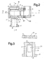
- Fig. 2 On the underside of the housing 13 is a circular, recessed seat 21 and a housing opening 20 surrounded by this for receiving the mounting flange 17, which is attached or integrally formed with one at its rear hollow cylindrical flange core 23 forms a detachable from the housing 13 unit.
- the mounting flange 17 surrounds the inflow opening 15.
- an opening or a window 25 is provided, through which the inflowing compressed air from the tubular flange core 23 enters the housing 13 of the muffler.
- the hollow cylindrical Flanschkern mainly for reasons of soundproofing, closed by a solid bottom wall 24.
- a recessed, circular seat 27 for receiving a flange plate 29 serving as an abutment plate.
- Mounting flange 17, flange core 23 and flange cover 29 have openings 31, 33 (see FIG Fig. 3 ), for receiving clamping screws (not shown), with which the mounting flange 17 and the flange 29 are connected to each other and against the housing 13, ie against the flat bottom surface of the seats 21, 27 can be tightened.
- this expansion bolts are used, which are tightened with a predetermined torque to produce a defined surface pressure.
- sealing rings 35 are arranged in the seats 21 and 20 .
- the number of clamping screws can z. B. four.
- clamping screws When tightening the clamping screws mounting flange 17 and flange 29 are in their seats 21, 27 preferably flush with the housing 13.
- the length of the clamping screws is greater than the height of the muffler housing 13 so that the inserted into the openings 33, 31 clamping screws down protrude beyond the mounting flange 15 and in corresponding threaded holes (not shown) of the connecting flange 9 of the compressor 1 can be screwed.
- the clamping screws thus have a dual function, namely to clamp the mounting flange 17 and the flange 29 against each other and against the seals 35 in the seats 21, 27 and to attach the entire muffler to the flange 7 of the compressor.
- the housing 13 can be rotated relative to the mounting flange 17 about the axis AA of the inlet opening 15 and fixed by tightening the clamping screws in any angular position relative to the compressor 1.
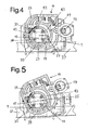
- FIG. 4 and FIG. 5 show top views of the top of the compressor 1 with attached muffler 11, wherein the compressor is mounted on the chassis 37 of a transport vehicle.
- Fig. 5 illustrated in comparison to Fig. 4 How the silencer 11 can be infinitely angularly adjusted relative to the compressor 1 after loosening of the mounting flange 17 against the housing 13 clamping screws and fixed by tightening the clamping screws in a desired angular position relative to the compressor 1.
- the angular adjustment of the muffler takes place about an axis of rotation which is concentric with the central axis of the inlet opening 15 of the muffler or the central axis of the connecting flange 9 of the compressor ( Fig. 1 ).
- the corners of the housing 13 of the muffler 11 are at least partially rounded, as indicated at 39.
- This construction of the muffler 11 with removable and interchangeable mounting flange 17 and flange 29 allows in addition to the continuous angle adjustment about the axis AA in Fig. 2 an additional degree of freedom of adjustment of the muffler 11 relative to the compressor 1, namely by turning by 180 ° about an axis BB perpendicular to the axis AA (see. Fig. 2 ).
- the horizontally cut representation of the muffler 11 in Fig. 4 also illustrates an inventive preferred design of the flow path of the compressed air in the muffler from the inlet port 15 to the outlet port 19.
- the inserted into the housing 13 tubular flange core 23 is over more than half, preferably about three quarters of its circumference of a curved wall 41 and an adjoining part of the housing wall surrounded so that they have a substantially constant distance from the peripheral surface of the Flanschkerns 23, so that a ring channel 43 is formed of substantially constant width.
- As flow obstacles lining with insulating material, metal membranes or the like. (Not shown) is provided.
- the second advantage of the illustrated construction of the muffler is that by suitably dimensioning the width of the annular channel 43, and choosing a suitable material for the walls bounding it, the annular channel 43 can be acoustically tuned to the frequency spectrum to be attenuated, so that an additional sound reduction is achieved.
- the compressed air After the compressed air has passed through the sound-absorbing flow path in the housing 13 of the muffler, it passes to the outlet opening 19, via a housing projection 47, in which a deflection of the compressed air by 90 ° upwards.
- the deflection lug 47 is attached to the main part of the housing 13 of the muffler 11 by fastening screws 49 and can be removed after loosening the screws 49 and in at least one rotated by 180 ° position, possibly also in two rotated by 90 ° positions, again attached, so that the outflow direction of the silenced compressed air is directed downward or to the side.
Landscapes
- Engineering & Computer Science (AREA)
- Mechanical Engineering (AREA)
- General Engineering & Computer Science (AREA)
- Compressor (AREA)
Applications Claiming Priority (1)
| Application Number | Priority Date | Filing Date | Title |
|---|---|---|---|
| DE202007005097U DE202007005097U1 (de) | 2007-04-05 | 2007-04-05 | Schalldämpfer zur Verwendung an einem Kompressor |
Publications (3)
| Publication Number | Publication Date |
|---|---|
| EP1978259A2 true EP1978259A2 (fr) | 2008-10-08 |
| EP1978259A3 EP1978259A3 (fr) | 2014-07-30 |
| EP1978259B1 EP1978259B1 (fr) | 2017-06-14 |
Family
ID=39629149
Family Applications (1)
| Application Number | Title | Priority Date | Filing Date |
|---|---|---|---|
| EP08006884.4A Not-in-force EP1978259B1 (fr) | 2007-04-05 | 2008-04-04 | Amortisseur de bruit destiné à l'utilisation sur un compresseur |
Country Status (2)
| Country | Link |
|---|---|
| EP (1) | EP1978259B1 (fr) |
| DE (1) | DE202007005097U1 (fr) |
Families Citing this family (6)
| Publication number | Priority date | Publication date | Assignee | Title |
|---|---|---|---|---|
| DE202010006419U1 (de) | 2010-05-04 | 2010-09-02 | Emico Gmbh | Breitbandig dämpfende Vorrichtung zur Schalldämpfung bei Industrieeinrichtungen, Großanlagen oder Maschinen |
| US10808969B2 (en) | 2015-08-11 | 2020-10-20 | Carrier Corporation | Screw compressor economizer plenum for pulsation reduction |
| CN108138775B (zh) * | 2015-10-02 | 2020-11-20 | 开利公司 | 螺杆压缩机谐振器阵列 |
| EP3861213B1 (fr) * | 2018-10-02 | 2023-12-13 | Carrier Corporation | Résonateur à plusieurs étages pour compresseur |
| CN113883062A (zh) * | 2021-09-18 | 2022-01-04 | 中国船舶重工集团公司第七一一研究所 | 螺杆压缩机用消音吸收器 |
| DE102021134652B3 (de) | 2021-12-23 | 2023-05-11 | Man Energy Solutions Se | Schraubenkompressor |
Family Cites Families (4)
| Publication number | Priority date | Publication date | Assignee | Title |
|---|---|---|---|---|
| DD292507A5 (de) * | 1990-03-12 | 1991-08-01 | Metallwerk Oranienburg Gmbh,De | Schalldaempferbefestigung |
| DE29904410U1 (de) * | 1999-03-10 | 2000-07-20 | GHH-RAND Schraubenkompressoren GmbH & Co. KG, 46145 Oberhausen | Schraubenkompressor |
| DE202004002341U1 (de) * | 2004-02-13 | 2004-05-19 | Schübler Fahrzeugtechnik GmbH | Versorgungsaggregateanordnung für ein Kraftfahrzeug |
| US7549509B2 (en) * | 2005-04-21 | 2009-06-23 | Ingersoll-Rand Company | Double throat pulsation dampener for a compressor |
-
2007
- 2007-04-05 DE DE202007005097U patent/DE202007005097U1/de not_active Expired - Lifetime
-
2008
- 2008-04-04 EP EP08006884.4A patent/EP1978259B1/fr not_active Not-in-force
Also Published As
| Publication number | Publication date |
|---|---|
| EP1978259B1 (fr) | 2017-06-14 |
| DE202007005097U1 (de) | 2008-08-07 |
| EP1978259A3 (fr) | 2014-07-30 |
Similar Documents
| Publication | Publication Date | Title |
|---|---|---|
| EP1978259B1 (fr) | Amortisseur de bruit destiné à l'utilisation sur un compresseur | |
| EP0920587A1 (fr) | Compresseur frigorifique | |
| WO2001020180A1 (fr) | Dispositif a paliers | |
| EP1470320B1 (fr) | Dispositif de fixation pour un turbocompresseur | |
| DE102013217939A1 (de) | Vorrichtung zur Halterung und Justierung eines Sensors | |
| EP3121051A1 (fr) | Reservoir de vehicule | |
| EP1099829B1 (fr) | Pièce d'insertion pour silencieux | |
| DE29618052U1 (de) | Lenkrad-Verriegelungsvorrichtung | |
| WO2008148443A1 (fr) | Ventilateur pour véhicule à moteur | |
| EP3538728B1 (fr) | Palier rotatif pour battant latéral d'un véhicule | |
| DE202004003811U1 (de) | Volumenstromregler | |
| EP1603776B1 (fr) | Dispositif de protection de passager | |
| DE102006009602A1 (de) | Traganordnung eines Behälters an einem tragenden Bauteil eines Lastkraftwagens | |
| DE102007034312B4 (de) | Gehäuse für ein Be- und Entlüftungsventil für Rohrleitungen bzw. Armaturen | |
| DE102017216226B4 (de) | Antriebseinrichtung für ein Kraftfahrzeug sowie entsprechendes Kraftfahrzeug | |
| EP1564060B1 (fr) | Disposition d'une unité auxiliaire pour un véhicule à moteur | |
| EP3322622A1 (fr) | Système amortisseur de bruit | |
| EP1038737B1 (fr) | Agencement de montage d'un module de coussin gonflable | |
| DE10111369A1 (de) | Dämpfereinsatz | |
| DE202006011298U1 (de) | Schalldämpfeinrichtung und damit ausgestattete Ventileinrichtung | |
| EP1853770A1 (fr) | Robinetterie de distribution d'eau sanitaire comprenant un dispositif de direction du jet permettant de devier l'ecoulement de l'eau sortant | |
| DE102005008730A1 (de) | Durchschraubter Luftkanal | |
| EP4577727A1 (fr) | Ventilateur à jet | |
| EP1762448B1 (fr) | Dispositif pour l'humidification de la vitre d'un véhicule et combinaison de ce dispositif avec une | |
| DE202008002655U1 (de) | Abgasendrohr mit Klappensteuerung im Aufnahmerohr für Kraftfahrzeuge |
Legal Events
| Date | Code | Title | Description |
|---|---|---|---|
| PUAI | Public reference made under article 153(3) epc to a published international application that has entered the european phase |
Free format text: ORIGINAL CODE: 0009012 |
|
| AK | Designated contracting states |
Kind code of ref document: A2 Designated state(s): AT BE BG CH CY CZ DE DK EE ES FI FR GB GR HR HU IE IS IT LI LT LU LV MC MT NL NO PL PT RO SE SI SK TR |
|
| AX | Request for extension of the european patent |
Extension state: AL BA MK RS |
|
| PUAL | Search report despatched |
Free format text: ORIGINAL CODE: 0009013 |
|
| AK | Designated contracting states |
Kind code of ref document: A3 Designated state(s): AT BE BG CH CY CZ DE DK EE ES FI FR GB GR HR HU IE IS IT LI LT LU LV MC MT NL NO PL PT RO SE SI SK TR |
|
| AX | Request for extension of the european patent |
Extension state: AL BA MK RS |
|
| RIC1 | Information provided on ipc code assigned before grant |
Ipc: F04C 29/06 20060101AFI20140625BHEP Ipc: F16L 55/027 20060101ALI20140625BHEP |
|
| 17P | Request for examination filed |
Effective date: 20150130 |
|
| RBV | Designated contracting states (corrected) |
Designated state(s): AT BE BG CH CY CZ DE DK EE ES FI FR GB GR HR HU IE IS IT LI LT LU LV MC MT NL NO PL PT RO SE SI SK TR |
|
| AKX | Designation fees paid |
Designated state(s): AT BE BG CH CY CZ DE DK EE ES FI FR GB GR HR HU IE IS IT LI LT LU LV MC MT NL NO PL PT RO SE SI SK TR |
|
| AXX | Extension fees paid |
Extension state: RS Extension state: AL Extension state: BA Extension state: MK |
|
| 17Q | First examination report despatched |
Effective date: 20160520 |
|
| GRAP | Despatch of communication of intention to grant a patent |
Free format text: ORIGINAL CODE: EPIDOSNIGR1 |
|
| STAA | Information on the status of an ep patent application or granted ep patent |
Free format text: STATUS: GRANT OF PATENT IS INTENDED |
|
| INTG | Intention to grant announced |
Effective date: 20161118 |
|
| GRAS | Grant fee paid |
Free format text: ORIGINAL CODE: EPIDOSNIGR3 |
|
| GRAA | (expected) grant |
Free format text: ORIGINAL CODE: 0009210 |
|
| STAA | Information on the status of an ep patent application or granted ep patent |
Free format text: STATUS: THE PATENT HAS BEEN GRANTED |
|
| AK | Designated contracting states |
Kind code of ref document: B1 Designated state(s): AT BE BG CH CY CZ DE DK EE ES FI FR GB GR HR HU IE IS IT LI LT LU LV MC MT NL NO PL PT RO SE SI SK TR |
|
| RAP1 | Party data changed (applicant data changed or rights of an application transferred) |
Owner name: INGERSOLL-RAND INTERNATIONAL LIMITED (IRLAND) |
|
| REG | Reference to a national code |
Ref country code: GB Ref legal event code: FG4D Free format text: NOT ENGLISH |
|
| REG | Reference to a national code |
Ref country code: CH Ref legal event code: EP Ref country code: AT Ref legal event code: REF Ref document number: 901263 Country of ref document: AT Kind code of ref document: T Effective date: 20170615 |
|
| REG | Reference to a national code |
Ref country code: IE Ref legal event code: FG4D Free format text: LANGUAGE OF EP DOCUMENT: GERMAN |
|
| REG | Reference to a national code |
Ref country code: DE Ref legal event code: R096 Ref document number: 502008015377 Country of ref document: DE |
|
| REG | Reference to a national code |
Ref country code: NL Ref legal event code: MP Effective date: 20170614 |
|
| REG | Reference to a national code |
Ref country code: LT Ref legal event code: MG4D |
|
| PG25 | Lapsed in a contracting state [announced via postgrant information from national office to epo] |
Ref country code: ES Free format text: LAPSE BECAUSE OF FAILURE TO SUBMIT A TRANSLATION OF THE DESCRIPTION OR TO PAY THE FEE WITHIN THE PRESCRIBED TIME-LIMIT Effective date: 20170614 Ref country code: NO Free format text: LAPSE BECAUSE OF FAILURE TO SUBMIT A TRANSLATION OF THE DESCRIPTION OR TO PAY THE FEE WITHIN THE PRESCRIBED TIME-LIMIT Effective date: 20170914 Ref country code: LT Free format text: LAPSE BECAUSE OF FAILURE TO SUBMIT A TRANSLATION OF THE DESCRIPTION OR TO PAY THE FEE WITHIN THE PRESCRIBED TIME-LIMIT Effective date: 20170614 Ref country code: FI Free format text: LAPSE BECAUSE OF FAILURE TO SUBMIT A TRANSLATION OF THE DESCRIPTION OR TO PAY THE FEE WITHIN THE PRESCRIBED TIME-LIMIT Effective date: 20170614 Ref country code: HR Free format text: LAPSE BECAUSE OF FAILURE TO SUBMIT A TRANSLATION OF THE DESCRIPTION OR TO PAY THE FEE WITHIN THE PRESCRIBED TIME-LIMIT Effective date: 20170614 Ref country code: GR Free format text: LAPSE BECAUSE OF FAILURE TO SUBMIT A TRANSLATION OF THE DESCRIPTION OR TO PAY THE FEE WITHIN THE PRESCRIBED TIME-LIMIT Effective date: 20170915 |
|
| PG25 | Lapsed in a contracting state [announced via postgrant information from national office to epo] |
Ref country code: BG Free format text: LAPSE BECAUSE OF FAILURE TO SUBMIT A TRANSLATION OF THE DESCRIPTION OR TO PAY THE FEE WITHIN THE PRESCRIBED TIME-LIMIT Effective date: 20170914 Ref country code: LV Free format text: LAPSE BECAUSE OF FAILURE TO SUBMIT A TRANSLATION OF THE DESCRIPTION OR TO PAY THE FEE WITHIN THE PRESCRIBED TIME-LIMIT Effective date: 20170614 Ref country code: NL Free format text: LAPSE BECAUSE OF FAILURE TO SUBMIT A TRANSLATION OF THE DESCRIPTION OR TO PAY THE FEE WITHIN THE PRESCRIBED TIME-LIMIT Effective date: 20170614 Ref country code: SE Free format text: LAPSE BECAUSE OF FAILURE TO SUBMIT A TRANSLATION OF THE DESCRIPTION OR TO PAY THE FEE WITHIN THE PRESCRIBED TIME-LIMIT Effective date: 20170614 |
|
| PG25 | Lapsed in a contracting state [announced via postgrant information from national office to epo] |
Ref country code: EE Free format text: LAPSE BECAUSE OF FAILURE TO SUBMIT A TRANSLATION OF THE DESCRIPTION OR TO PAY THE FEE WITHIN THE PRESCRIBED TIME-LIMIT Effective date: 20170614 Ref country code: CZ Free format text: LAPSE BECAUSE OF FAILURE TO SUBMIT A TRANSLATION OF THE DESCRIPTION OR TO PAY THE FEE WITHIN THE PRESCRIBED TIME-LIMIT Effective date: 20170614 Ref country code: SK Free format text: LAPSE BECAUSE OF FAILURE TO SUBMIT A TRANSLATION OF THE DESCRIPTION OR TO PAY THE FEE WITHIN THE PRESCRIBED TIME-LIMIT Effective date: 20170614 Ref country code: RO Free format text: LAPSE BECAUSE OF FAILURE TO SUBMIT A TRANSLATION OF THE DESCRIPTION OR TO PAY THE FEE WITHIN THE PRESCRIBED TIME-LIMIT Effective date: 20170614 |
|
| PG25 | Lapsed in a contracting state [announced via postgrant information from national office to epo] |
Ref country code: IS Free format text: LAPSE BECAUSE OF FAILURE TO SUBMIT A TRANSLATION OF THE DESCRIPTION OR TO PAY THE FEE WITHIN THE PRESCRIBED TIME-LIMIT Effective date: 20171014 Ref country code: IT Free format text: LAPSE BECAUSE OF FAILURE TO SUBMIT A TRANSLATION OF THE DESCRIPTION OR TO PAY THE FEE WITHIN THE PRESCRIBED TIME-LIMIT Effective date: 20170614 Ref country code: PL Free format text: LAPSE BECAUSE OF FAILURE TO SUBMIT A TRANSLATION OF THE DESCRIPTION OR TO PAY THE FEE WITHIN THE PRESCRIBED TIME-LIMIT Effective date: 20170614 |
|
| REG | Reference to a national code |
Ref country code: DE Ref legal event code: R097 Ref document number: 502008015377 Country of ref document: DE |
|
| PLBE | No opposition filed within time limit |
Free format text: ORIGINAL CODE: 0009261 |
|
| STAA | Information on the status of an ep patent application or granted ep patent |
Free format text: STATUS: NO OPPOSITION FILED WITHIN TIME LIMIT |
|
| PG25 | Lapsed in a contracting state [announced via postgrant information from national office to epo] |
Ref country code: DK Free format text: LAPSE BECAUSE OF FAILURE TO SUBMIT A TRANSLATION OF THE DESCRIPTION OR TO PAY THE FEE WITHIN THE PRESCRIBED TIME-LIMIT Effective date: 20170614 |
|
| 26N | No opposition filed |
Effective date: 20180315 |
|
| PG25 | Lapsed in a contracting state [announced via postgrant information from national office to epo] |
Ref country code: SI Free format text: LAPSE BECAUSE OF FAILURE TO SUBMIT A TRANSLATION OF THE DESCRIPTION OR TO PAY THE FEE WITHIN THE PRESCRIBED TIME-LIMIT Effective date: 20170614 |
|
| PG25 | Lapsed in a contracting state [announced via postgrant information from national office to epo] |
Ref country code: MT Free format text: LAPSE BECAUSE OF FAILURE TO SUBMIT A TRANSLATION OF THE DESCRIPTION OR TO PAY THE FEE WITHIN THE PRESCRIBED TIME-LIMIT Effective date: 20170614 |
|
| REG | Reference to a national code |
Ref country code: DE Ref legal event code: R119 Ref document number: 502008015377 Country of ref document: DE |
|
| PG25 | Lapsed in a contracting state [announced via postgrant information from national office to epo] |
Ref country code: MC Free format text: LAPSE BECAUSE OF FAILURE TO SUBMIT A TRANSLATION OF THE DESCRIPTION OR TO PAY THE FEE WITHIN THE PRESCRIBED TIME-LIMIT Effective date: 20170614 |
|
| REG | Reference to a national code |
Ref country code: CH Ref legal event code: PL |
|
| REG | Reference to a national code |
Ref country code: BE Ref legal event code: MM Effective date: 20180430 |
|
| GBPC | Gb: european patent ceased through non-payment of renewal fee |
Effective date: 20180404 |
|
| REG | Reference to a national code |
Ref country code: IE Ref legal event code: MM4A |
|
| PG25 | Lapsed in a contracting state [announced via postgrant information from national office to epo] |
Ref country code: LU Free format text: LAPSE BECAUSE OF NON-PAYMENT OF DUE FEES Effective date: 20180404 Ref country code: DE Free format text: LAPSE BECAUSE OF NON-PAYMENT OF DUE FEES Effective date: 20181101 |
|
| PG25 | Lapsed in a contracting state [announced via postgrant information from national office to epo] |
Ref country code: LI Free format text: LAPSE BECAUSE OF NON-PAYMENT OF DUE FEES Effective date: 20180430 Ref country code: CH Free format text: LAPSE BECAUSE OF NON-PAYMENT OF DUE FEES Effective date: 20180430 Ref country code: GB Free format text: LAPSE BECAUSE OF NON-PAYMENT OF DUE FEES Effective date: 20180404 Ref country code: BE Free format text: LAPSE BECAUSE OF NON-PAYMENT OF DUE FEES Effective date: 20180430 |
|
| PG25 | Lapsed in a contracting state [announced via postgrant information from national office to epo] |
Ref country code: IE Free format text: LAPSE BECAUSE OF NON-PAYMENT OF DUE FEES Effective date: 20180404 Ref country code: FR Free format text: LAPSE BECAUSE OF NON-PAYMENT OF DUE FEES Effective date: 20180430 |
|
| REG | Reference to a national code |
Ref country code: AT Ref legal event code: MM01 Ref document number: 901263 Country of ref document: AT Kind code of ref document: T Effective date: 20180404 |
|
| PG25 | Lapsed in a contracting state [announced via postgrant information from national office to epo] |
Ref country code: AT Free format text: LAPSE BECAUSE OF NON-PAYMENT OF DUE FEES Effective date: 20180404 |
|
| PG25 | Lapsed in a contracting state [announced via postgrant information from national office to epo] |
Ref country code: TR Free format text: LAPSE BECAUSE OF FAILURE TO SUBMIT A TRANSLATION OF THE DESCRIPTION OR TO PAY THE FEE WITHIN THE PRESCRIBED TIME-LIMIT Effective date: 20170614 |
|
| PG25 | Lapsed in a contracting state [announced via postgrant information from national office to epo] |
Ref country code: HU Free format text: LAPSE BECAUSE OF FAILURE TO SUBMIT A TRANSLATION OF THE DESCRIPTION OR TO PAY THE FEE WITHIN THE PRESCRIBED TIME-LIMIT; INVALID AB INITIO Effective date: 20080404 Ref country code: PT Free format text: LAPSE BECAUSE OF FAILURE TO SUBMIT A TRANSLATION OF THE DESCRIPTION OR TO PAY THE FEE WITHIN THE PRESCRIBED TIME-LIMIT Effective date: 20170614 |
|
| PG25 | Lapsed in a contracting state [announced via postgrant information from national office to epo] |
Ref country code: CY Free format text: LAPSE BECAUSE OF FAILURE TO SUBMIT A TRANSLATION OF THE DESCRIPTION OR TO PAY THE FEE WITHIN THE PRESCRIBED TIME-LIMIT Effective date: 20170614 |