EP1762759A2 - Mécanisme de commande pour une soupape à vide - Google Patents
Mécanisme de commande pour une soupape à vide Download PDFInfo
- Publication number
- EP1762759A2 EP1762759A2 EP06018520A EP06018520A EP1762759A2 EP 1762759 A2 EP1762759 A2 EP 1762759A2 EP 06018520 A EP06018520 A EP 06018520A EP 06018520 A EP06018520 A EP 06018520A EP 1762759 A2 EP1762759 A2 EP 1762759A2
- Authority
- EP
- European Patent Office
- Prior art keywords
- plate
- grooves
- rolling elements
- valve mechanism
- mechanism according
- Prior art date
- Legal status (The legal status is an assumption and is not a legal conclusion. Google has not performed a legal analysis and makes no representation as to the accuracy of the status listed.)
- Granted
Links
Images




Classifications
-
- F—MECHANICAL ENGINEERING; LIGHTING; HEATING; WEAPONS; BLASTING
- F16—ENGINEERING ELEMENTS AND UNITS; GENERAL MEASURES FOR PRODUCING AND MAINTAINING EFFECTIVE FUNCTIONING OF MACHINES OR INSTALLATIONS; THERMAL INSULATION IN GENERAL
- F16K—VALVES; TAPS; COCKS; ACTUATING-FLOATS; DEVICES FOR VENTING OR AERATING
- F16K3/00—Gate valves or sliding valves, i.e. cut-off apparatus with closing members having a sliding movement along the seat for opening and closing
- F16K3/02—Gate valves or sliding valves, i.e. cut-off apparatus with closing members having a sliding movement along the seat for opening and closing with flat sealing faces; Packings therefor
- F16K3/16—Gate valves or sliding valves, i.e. cut-off apparatus with closing members having a sliding movement along the seat for opening and closing with flat sealing faces; Packings therefor with special arrangements for separating the sealing faces or for pressing them together
- F16K3/18—Gate valves or sliding valves, i.e. cut-off apparatus with closing members having a sliding movement along the seat for opening and closing with flat sealing faces; Packings therefor with special arrangements for separating the sealing faces or for pressing them together by movement of the closure members
- F16K3/184—Gate valves or sliding valves, i.e. cut-off apparatus with closing members having a sliding movement along the seat for opening and closing with flat sealing faces; Packings therefor with special arrangements for separating the sealing faces or for pressing them together by movement of the closure members by means of cams
-
- F—MECHANICAL ENGINEERING; LIGHTING; HEATING; WEAPONS; BLASTING
- F16—ENGINEERING ELEMENTS AND UNITS; GENERAL MEASURES FOR PRODUCING AND MAINTAINING EFFECTIVE FUNCTIONING OF MACHINES OR INSTALLATIONS; THERMAL INSULATION IN GENERAL
- F16K—VALVES; TAPS; COCKS; ACTUATING-FLOATS; DEVICES FOR VENTING OR AERATING
- F16K51/00—Other details not peculiar to particular types of valves or cut-off apparatus
- F16K51/02—Other details not peculiar to particular types of valves or cut-off apparatus specially adapted for high-vacuum installations
Definitions
- the invention relates to a valve mechanism for a vacuum valve according to the preamble of claim 1.
- Such vacuum valves are preferably used for the closure of through-openings in vacuum systems.
- valve mechanism can also be used for other positively driven valves, such. B. for gate valves in liquid-carrying lines and the like.
- a known valve mechanism is based on the same applicant in the form of EP 662 575 B1 back.
- a rolling movement of the valve disk is achieved via fixedly mounted bearing axes, which is associated with increased effort.
- the bearing axles shown there are not as high load capacity as freely guided rollers, which are guided without bearings in corresponding receptacles.
- bearingless guided axes also referred to as roller-like rolling elements
- JP-2001090849 A1 JP-2001090849 A1
- a rotationally driven first plate distributed on the circumference On a rotationally driven first plate distributed on the circumference, obliquely rising grooves are incorporated, in which balls are guided displaceably. These balls engage in mating grooves of a second middle plate opposite the grooves in the first plate. On the opposite side of this middle plate are in turn grooves with it slidably guided balls mounted, which engage in associated grooves of a third plate.
- This third plate is finally the valve plate (valve plate) which - according to the rotational position of the other two plates - sealingly abuts the passage in the housing or stands out from it.
- EP 0662 575 B1 has similar guides with closed grooves, but run in one-sided bearing bolts. These bearings must be kept relatively small for space requirements, so they work hard at the limit of load capacity.
- the object of the invention is a valve mechanism for a vacuum valve according to the subject of JP-2001090849 to propose, in which the opening can be done with just as high forces as closing and that the rolling elements are kept trouble-free and secure against displacement.
- the invention is characterized by the technical teaching of claim 1.
- An essential feature of the invention is that only at least two mutually displaceable parts are present, wherein the one part is the drive plate and the other part of the plate, that further in the drive plate at least one groove is incorporated, with a complementary groove in the adjacent plate overlaps and overlaps and that in the overlap region between these two complementarily complementary grooves in each case a roller-shaped rolling elements is arranged.
- the complementary grooves are closed in one part, as well as in the adjacent other part and thus the rolling elements are secured up and down against falling or unintentional displacement. Therefore, the closed grooves only allow engagement of the rolling elements in the direction of their axial longitudinal extent. Such a feature can be derived from the mentioned JP 20011090849 do not remove.
- rollers proposed here are not stored in itself parts with balls, inner and outer ring, but only freely guided rolling elements without the use of another mechanism. Therefore, they are much higher load capacity for the same outer diameter.
- the invention accordingly enables very high sealing forces and also very high detachment forces.
- a particular advantage of the invention is that in the simplest case, no return springs are needed, because the rolling elements are completely positively constrained in associated receptacles between the grooves and are forcibly guided both in the direction of Dichtabhebedoch and in the opposite direction.
- the invention is not limited to that the rolling elements pass as a roller body from one side of the arrangement to the other side.
- the rolling elements are only partially available as rollers or the like and, for example, do not pass from one to the other side of the valve over the entire width and are materially connected to each other.
- the invention is not limited to use round cylindrical rolling elements.
- Other shapes may also be used, such as, in particular, triangular bodies that also provide a straight rolling motion with rounded spherical surfaces.
- the invention preferably uses a carriage, which is formed driven in the horizontal direction.
- the type of drive is not described in detail in the present invention. This drive is known in the art. It is based on the revelation in the EP 0 662 575 B1 whose contents are to be encompassed by the present disclosure.
- the carriage works with a total of four bearing rollers. It can also be used other rolling bearings, in particular spherical roller bearings and the like.
- this carriage is also referred to as the drive plate, because it is a plate-shaped body which is slidably driven with associated rollers on a tread in a housing.
- the mounted on the carriage plate is longitudinally guided in the form of a Nuten Entry, said Nuten Entry forces at the end of a lifting movement of the plate in the direction of the seal seat of the plate.
- Such a lifting mechanism is z. B. a rocker arm or the like.
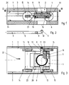
- a valve mechanism is generally shown in a vacuum valve, wherein in a housing 1 a vertically continuous valve opening 2 is arranged, which is closed by the plate 4 by means of a sealing element 8.
- the slider shown in Figures 1 and 3 consists essentially of a drive plate 14 which is displaceably driven in the direction of arrow 22 and in the opposite direction thereto (see also Figure 6).
- the movement of the plate 4 is z. B. accomplished in Figure 1 by means of an end bent groove 3, said groove 3 is incorporated on both sides in the housing 1. In this groove 3 engage on both sides bearings 9 a.
- the groove 3 and its function can be seen more clearly in FIG.
- the bearing 9 moves only along the axis 10, which has a perpendicular to the main direction extending part 11 at the front end, and between them is preferred to the Achieving a smooth movement a radius 12 incorporated. It is understood that the bearing running in this groove gets some air so that it can roll on the running surface as intended.
- the bearing 9 is integrally connected to the plate 4 via the claws 13 or fixed.
- the bearing 9 has exclusively controlling functions, it is burdened by the sealing forces or by the detachment forces in any way and can therefore be kept very small. It only carries the dead weight of hanging on him parts such as the plate. 4
- the drive plate 14 has a plurality of bearings 15, which make them movable in the drive plane, but otherwise in any axis displaceable.
- the bearings 15 are in this case designed as rollers which roll on associated running surfaces 24 from the inside of the housing 1
- either the lower running surface 24 or the opposite running surface 24 ' is used as a drainage surface for the bearings 15 either.
- the rolling elements 16 are formed as round profiled rollers or as pins continuously (over the entire width of the plate 4) (see Figure 3). The respective outermost end of each rolling body 16 engages in an associated control groove 23 in the region of the drive plate 14.
- the rolling element 16 extends over the entire width the arrangement extends. It can also be provided that this storage consists of two mutually aligned and not interconnected rolling elements. Thus, the rolling element 16 may be interrupted in the middle and there are then two WälzShmaschinemaschine available, which are held exactly in alignment with each other in the plate 4.
- Such arrangements with divided rolling elements 16 are particularly preferred for large nominal sizes of vacuum valves.
- the shape of the grooves 6 and 7 is preferably made bent, but it can also be selected other shapes such as oblique with constant angle, obliquely with 2 angles and a transition radius between them, obliquely and in the range of high forces straight, with and without small notches Snap the end position.
- An example of such different Nutenformen shows the figure 7.
- the grooves are provided in the direction perpendicular to their longitudinal extent with circumferential boundary walls. This also applies to the upper and lower end faces, which are formed by the respective groove bottom. It is therefore possible only one engagement of the rolling elements in a vertical plane to the plane of the longitudinal extent of the grooves.
- the two rolling elements 16 which are guided at a distance from one another and parallel to one another lie in parallel grooves 6 of the plate 4 which have a mutual distance from each other.
- a synchronizing plate 36 is used, which is arranged on one side of the plate 4 in the space between the respective outer side surface of the plate 4 and the opposite surface of the drive plate fourteenth
- this synchronization device with synchronizing plates also applies to the embodiment according to FIG. 5, where twice the number of rolling elements is shown.
- each arranged on one side of rolling elements in the direction of the front and rear pass through the synchronizing, so that here - in this embodiment - the front and rear rolling elements are always moved in synchronism by the interposed synchronizing.
- These rolling elements 17 can - as shown in Figure 4 - have at one or more points a groove 25 which receives a resilient body. In the drawing, this is an O-ring 18. At the opposite location in the drive plate 14 is then a recess 19, which ensures that the O-ring 18 is slightly pressed only on one side (tread 26).
- the device with The O-ring 25 according to FIG. 4 may, but need not, be dispensed with in the embodiment according to FIGS. 5 and 6, because there already a spring element 20 ensures that the rolling elements 16 with slight bias of these springs 20 against the corresponding surfaces in the grooves 6 and 7 are pressed.
- the spring element is used as a stop 21 for the front position.
- a spring element as drawn here can be used as a leaf spring, but it can also be used with coil springs, disc springs or other resilient elements constructions that press the plate 4 against the counter plate 5 or against the drive plate 14.
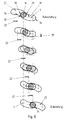
- FIG. 8 shows in more detail a sequence of movements of the two mutually sliding grooves 6, 23.
- control groove 23 has moved to the right of the leg 22 '(e.g., by an amount of 6 mm) with the groove 6 (horizontally stopped).
- the groove 6 is vertically raised in the direction of the arrow around the section 33 '.
- the receiving opening 32 has a round opening for receiving the rolling element 16 or 17th
- the receiving opening 32 opens to an oval.
- the control groove 23 has then moved completely to the right when the groove 6 is horizontally fixed. In this case, the maximum vertical stroke was exerted in the direction of arrow 33 on the bearing in the receiving opening rolling elements.
- groove 7 which, however, has the same function as the groove 6 in the plate 4.
- the rolling elements 16, 17 are otherwise protected against falling out in the direction of their longitudinal extension by external stops 28 on the drive plate 14.
- the advantage of the invention is that the connection between the drive plate 14 and the plate 4 (and optionally the Gegenteller 5) two complementary grooves 6, 23 (which are complementary to each other) through the stub of (roller or roller-shaped) rolling elements 16, 17 are bridged so as to achieve a positive guidance between the drive plate 14 and plate 4, 5. It is advantageous that the grooves are each closed laterally, d. H. it can not happen that the rolling elements 16, 17 fall out of the grooves, as was the case in the prior art.
- Figure 9 shows a perspective view of the plate 4 with the rolling elements 16, which roll in the grooves 23 of the drive plate 14.
- the two rod-shaped parallel parts of the drive plate 14 are pulled apart to better represent the plate 4 located in the space can.
- the parts 4 and 14 are formed at a close distance 35.
- FIG. 10 shows an enlarged view of FIG. 3, wherein a synchronizing plate 36 is shown as an additional part, which has two bores 37 which are penetrated by rolling elements 16 with bearing play.
- synchronizing plate 36 thus takes place a synchronization of the movement of the parallel spaced-apart rolling elements 16. If the rolling forward in the direction of rolling element 16 is changed in its position in the grooves 6, 23, thanks to the synchronizing plate 36 also in the running direction behind the rolling elements 16 taken away.
Landscapes
- Engineering & Computer Science (AREA)
- General Engineering & Computer Science (AREA)
- Mechanical Engineering (AREA)
- Sliding Valves (AREA)
- Details Of Valves (AREA)
- Sheets, Magazines, And Separation Thereof (AREA)
- Manipulator (AREA)
Applications Claiming Priority (1)
| Application Number | Priority Date | Filing Date | Title |
|---|---|---|---|
| DE102005043595A DE102005043595A1 (de) | 2005-09-12 | 2005-09-12 | Ventilmechanik für ein Vakuumventil |
Publications (3)
| Publication Number | Publication Date |
|---|---|
| EP1762759A2 true EP1762759A2 (fr) | 2007-03-14 |
| EP1762759A3 EP1762759A3 (fr) | 2008-07-16 |
| EP1762759B1 EP1762759B1 (fr) | 2011-03-02 |
Family
ID=37496816
Family Applications (1)
| Application Number | Title | Priority Date | Filing Date |
|---|---|---|---|
| EP06018520A Active EP1762759B1 (fr) | 2005-09-12 | 2006-09-05 | Mécanisme de commande pour une soupape à vide |
Country Status (5)
| Country | Link |
|---|---|
| US (1) | US7341237B2 (fr) |
| EP (1) | EP1762759B1 (fr) |
| JP (1) | JP5208392B2 (fr) |
| AT (1) | ATE500452T1 (fr) |
| DE (2) | DE102005043595A1 (fr) |
Cited By (2)
| Publication number | Priority date | Publication date | Assignee | Title |
|---|---|---|---|---|
| WO2018089482A1 (fr) | 2016-11-08 | 2018-05-17 | O.I. Corporation | Coulisseau intelligent |
| CN114341535A (zh) * | 2019-09-03 | 2022-04-12 | Vat控股公司 | 用于装载和/或卸载真空腔的真空阀 |
Families Citing this family (15)
| Publication number | Priority date | Publication date | Assignee | Title |
|---|---|---|---|---|
| TWI551798B (zh) * | 2015-02-06 | 2016-10-01 | 新萊應材科技有限公司 | 具有鎖定功能之閘閥 |
| CN106122580B (zh) * | 2015-02-15 | 2018-11-23 | 新莱应材科技有限公司 | 具有锁定功能的闸阀 |
| EP3159587A1 (fr) | 2015-02-16 | 2017-04-26 | King Lai Hygienic Materials Co., Ltd. | Robinet-vanne avec mécanisme d'étanchéité sécurisé |
| US9464721B2 (en) | 2015-02-23 | 2016-10-11 | King Lai Hygienic Material Co., Ltd | Gate valve with secure sealing mechanism |
| JP5990612B2 (ja) * | 2015-02-27 | 2016-09-14 | 新▲莱▼應材科技有限公司 | 仕切弁 |
| RU2612871C2 (ru) * | 2015-04-30 | 2017-03-13 | Кинг Лай Гигиеник Материалз Ко., Лтд. | Задвижка с защищенным запорным механизмом |
| JP6242450B2 (ja) * | 2016-08-12 | 2017-12-06 | 新▲莱▼應材科技有限公司 | 仕切弁 |
| RU2659619C2 (ru) * | 2016-09-02 | 2018-07-03 | Кинг Лай Гигиеник Материалз Ко., Лтд. | Задвижка с надежным запорным механизмом |
| US20190178390A1 (en) * | 2017-12-07 | 2019-06-13 | King Lai Hygienic Materials Co., Ltd | Spring free gate valve |
| CN108150663B (zh) * | 2018-01-11 | 2021-11-02 | 张跃 | 一种真空管道闸门 |
| TWI716250B (zh) * | 2020-01-02 | 2021-01-11 | 新萊應材科技有限公司 | 具有防塵功能之閘閥 |
| JP7722118B2 (ja) * | 2021-10-13 | 2025-08-13 | Smc株式会社 | ゲートバルブ |
| TWI835047B (zh) * | 2022-01-05 | 2024-03-11 | 新萊應材科技有限公司 | 利用彈力啟閉之閘閥 |
| CN115306915A (zh) * | 2022-07-29 | 2022-11-08 | 成都中科唯实仪器有限责任公司 | 一种真空插板阀 |
| CN116379174A (zh) * | 2023-04-11 | 2023-07-04 | 福建省真特阀门科技有限公司 | 一种零摩擦密封闸阀 |
Citations (3)
| Publication number | Priority date | Publication date | Assignee | Title |
|---|---|---|---|---|
| EP0662575B1 (fr) | 1993-12-08 | 1999-11-03 | Hubert Bösch | Mécanisme de vanne avec guidage forcé |
| JP2001090849A (ja) | 1999-09-22 | 2001-04-03 | V Tex:Kk | ゲートバルブの開閉装置 |
| US20020139954A1 (en) | 2001-03-28 | 2002-10-03 | V Tex Corporation | Gate valve |
Family Cites Families (22)
| Publication number | Priority date | Publication date | Assignee | Title |
|---|---|---|---|---|
| US681285A (en) * | 1900-11-07 | 1901-08-27 | Clemens Wehner | Stop-valve. |
| US983960A (en) * | 1910-09-16 | 1911-02-14 | Byron C Leavitt | Valve. |
| US1057308A (en) * | 1912-01-20 | 1913-03-25 | Byron C Leavitt | Valve. |
| DE636317C (de) * | 1930-10-27 | 1936-10-06 | Dango & Dienenthal Kg | Absperrschieber mit parallelen Dichtflaechen |
| US2502689A (en) * | 1944-08-17 | 1950-04-04 | Crane Co | Retractable gate valve |
| CH402537A (de) * | 1961-02-16 | 1965-11-15 | Licentia Gmbh | Schieberventil |
| JPS5650207Y2 (fr) * | 1972-05-11 | 1981-11-24 | ||
| US3973753A (en) * | 1974-03-18 | 1976-08-10 | Varian Associates | High vacuum gate valve |
| DE2601120A1 (de) * | 1976-01-14 | 1977-07-28 | Bergwerksverband Gmbh | Zugschieber zum absperren von gasen in rohrleitungen |
| US4480659A (en) * | 1981-11-05 | 1984-11-06 | Hps Corporation | Gate stop valve |
| US4408634A (en) * | 1981-11-05 | 1983-10-11 | Hps Corporation | Gate stop valve |
| DE3224387A1 (de) * | 1982-06-30 | 1984-01-12 | Schertler, Siegfried, 9469 Haag | Vakuumschieberventil |
| US4718637A (en) * | 1986-07-02 | 1988-01-12 | Mdc Vacuum Products Corporation | High vacuum gate valve having improved metal vacuum joint |
| US4903937A (en) * | 1987-09-24 | 1990-02-27 | Varian Associates, Inc. | Isolation valve for vacuum and non-vacuum application |
| US4846441A (en) * | 1988-06-20 | 1989-07-11 | Keystone International, Inc. | Methods and apparatus for adjusting a valve closure member |
| JP2864234B2 (ja) * | 1996-11-22 | 1999-03-03 | 株式会社ブイテックス | 摩擦の無い動力伝達装置 |
| US5722636A (en) * | 1996-12-18 | 1998-03-03 | Houston; James L. | Double disk gate assembly for block and bleed type valves |
| US6109167A (en) * | 1998-06-04 | 2000-08-29 | Gits Manufacturing Company | Actuator with axially movable O-rings between piston and housing |
| JP2001021048A (ja) * | 1999-06-29 | 2001-01-26 | Varian Inc | ランプアクチュエータ機構を有するゲートバルブ |
| US6431518B1 (en) * | 2001-01-11 | 2002-08-13 | Vat Holding Ag | Vacuum valve |
| US6612546B2 (en) * | 2001-08-01 | 2003-09-02 | Varian, Inc. | Gate valve with delayed retraction of counter plate |
| US6896239B1 (en) * | 2003-04-22 | 2005-05-24 | Arthur J. Brenes | Method and apparatus for locking a valve |
-
2005
- 2005-09-12 DE DE102005043595A patent/DE102005043595A1/de not_active Withdrawn
-
2006
- 2006-09-05 AT AT06018520T patent/ATE500452T1/de active
- 2006-09-05 EP EP06018520A patent/EP1762759B1/fr active Active
- 2006-09-05 DE DE502006008980T patent/DE502006008980D1/de active Active
- 2006-09-12 US US11/531,215 patent/US7341237B2/en active Active
- 2006-09-12 JP JP2006246979A patent/JP5208392B2/ja active Active
Patent Citations (3)
| Publication number | Priority date | Publication date | Assignee | Title |
|---|---|---|---|---|
| EP0662575B1 (fr) | 1993-12-08 | 1999-11-03 | Hubert Bösch | Mécanisme de vanne avec guidage forcé |
| JP2001090849A (ja) | 1999-09-22 | 2001-04-03 | V Tex:Kk | ゲートバルブの開閉装置 |
| US20020139954A1 (en) | 2001-03-28 | 2002-10-03 | V Tex Corporation | Gate valve |
Cited By (6)
| Publication number | Priority date | Publication date | Assignee | Title |
|---|---|---|---|---|
| WO2018089482A1 (fr) | 2016-11-08 | 2018-05-17 | O.I. Corporation | Coulisseau intelligent |
| EP3538900A4 (fr) * | 2016-11-08 | 2020-05-06 | O.I. Corporation | Coulisseau intelligent |
| US10816267B2 (en) | 2016-11-08 | 2020-10-27 | O.I. Corporation | Smart slide |
| CN114341535A (zh) * | 2019-09-03 | 2022-04-12 | Vat控股公司 | 用于装载和/或卸载真空腔的真空阀 |
| US11767931B2 (en) | 2019-09-03 | 2023-09-26 | Vat Holding Ag | Vacuum valve for loading and/or unloading a vacuum chamber |
| CN114341535B (zh) * | 2019-09-03 | 2023-11-28 | Vat控股公司 | 用于装载和/或卸载真空腔的真空阀 |
Also Published As
| Publication number | Publication date |
|---|---|
| ATE500452T1 (de) | 2011-03-15 |
| DE102005043595A1 (de) | 2007-04-19 |
| EP1762759A3 (fr) | 2008-07-16 |
| JP2007078186A (ja) | 2007-03-29 |
| US7341237B2 (en) | 2008-03-11 |
| JP5208392B2 (ja) | 2013-06-12 |
| EP1762759B1 (fr) | 2011-03-02 |
| DE502006008980D1 (de) | 2011-04-14 |
| US20070057220A1 (en) | 2007-03-15 |
Similar Documents
| Publication | Publication Date | Title |
|---|---|---|
| EP1762759B1 (fr) | Mécanisme de commande pour une soupape à vide | |
| DE3224387C2 (fr) | ||
| DE19600031C2 (de) | Vertikal einstellbarer Maschinenträger | |
| DE2332489A1 (de) | Vorrichtung zum hermetischen verschliessen mit einem rolltor | |
| DE102014115661A1 (de) | Scharnier mit variabler Reibung | |
| DE102010000556A1 (de) | Hubtor mit einer beweglichen Torblattführung | |
| WO2014075757A1 (fr) | Soupape à vide | |
| EP0178610B1 (fr) | Serrure | |
| WO2017025329A1 (fr) | Vanne, en particulier vanne de pression négative | |
| EP3380692B1 (fr) | Dispositif de paroi coulissante avec élément de recouvrement | |
| EP3752694B1 (fr) | Dispositif de stationnement de voiture | |
| DE19514846A1 (de) | Lagereinstellmechanismus für kolbenstangenlose Zylinder | |
| EP3825503A1 (fr) | Dispositif d'étanchéité d'une porte coulissante | |
| DE102014001071A1 (de) | Getakteter Drehtisch | |
| DE102010015920A1 (de) | Abkantpresse zum Biegen von Folien | |
| EP4051937B1 (fr) | Soupape à vide | |
| DE102007015199A1 (de) | Beschlag zur Verriegelung von Fenstern oder Türen | |
| EP3201413B1 (fr) | Ensemble de ferrures | |
| DE2655235A1 (de) | Balgartig faltbare jalousie fuer fenster und tueren sowie vorrichtung zum oeffnen und schliessen derselben | |
| DE69506325T2 (de) | Verschlusseinrichtung | |
| DE2616973C3 (de) | Pneumatischer Arbeitszylinder zur Betätigung und stufenlosen Arretierung von Stellgliedern | |
| DE102005021460A1 (de) | Verstelleinrichtung für Kupplungen und Getriebebremsen, insbesondere von Kraftfahrzeugen zum Verstellen eines einen Auflage- und Drehpunkt eines gebogenen Hebels bildenden Auflagerelements | |
| EP0723060A1 (fr) | Commande de séquence de fermeture | |
| DE102016113085A1 (de) | Wasserdichte Sektionaltor-Vorrichtung | |
| DE102007038789A1 (de) | Spannvorrichtung und Anordnung einer solchen Spannvorrichtung mit einer Spannzange |
Legal Events
| Date | Code | Title | Description |
|---|---|---|---|
| PUAI | Public reference made under article 153(3) epc to a published international application that has entered the european phase |
Free format text: ORIGINAL CODE: 0009012 |
|
| AK | Designated contracting states |
Kind code of ref document: A2 Designated state(s): AT BE BG CH CY CZ DE DK EE ES FI FR GB GR HU IE IS IT LI LT LU LV MC NL PL PT RO SE SI SK TR |
|
| AX | Request for extension of the european patent |
Extension state: AL BA HR MK YU |
|
| PUAL | Search report despatched |
Free format text: ORIGINAL CODE: 0009013 |
|
| AK | Designated contracting states |
Kind code of ref document: A3 Designated state(s): AT BE BG CH CY CZ DE DK EE ES FI FR GB GR HU IE IS IT LI LT LU LV MC NL PL PT RO SE SI SK TR |
|
| AX | Request for extension of the european patent |
Extension state: AL BA HR MK RS |
|
| 17P | Request for examination filed |
Effective date: 20081128 |
|
| AKX | Designation fees paid |
Designated state(s): AT BE BG CH CY CZ DE DK EE ES FI FR GB GR HU IE IS IT LI LT LU LV MC NL PL PT RO SE SI SK TR |
|
| 17Q | First examination report despatched |
Effective date: 20090727 |
|
| GRAP | Despatch of communication of intention to grant a patent |
Free format text: ORIGINAL CODE: EPIDOSNIGR1 |
|
| GRAS | Grant fee paid |
Free format text: ORIGINAL CODE: EPIDOSNIGR3 |
|
| GRAA | (expected) grant |
Free format text: ORIGINAL CODE: 0009210 |
|
| AK | Designated contracting states |
Kind code of ref document: B1 Designated state(s): AT BE BG CH CY CZ DE DK EE ES FI FR GB GR HU IE IS IT LI LT LU LV MC NL PL PT RO SE SI SK TR |
|
| REG | Reference to a national code |
Ref country code: GB Ref legal event code: FG4D Free format text: NOT ENGLISH |
|
| REG | Reference to a national code |
Ref country code: CH Ref legal event code: EP |
|
| REG | Reference to a national code |
Ref country code: IE Ref legal event code: FG4D Free format text: LANGUAGE OF EP DOCUMENT: GERMAN |
|
| REF | Corresponds to: |
Ref document number: 502006008980 Country of ref document: DE Date of ref document: 20110414 Kind code of ref document: P |
|
| REG | Reference to a national code |
Ref country code: DE Ref legal event code: R096 Ref document number: 502006008980 Country of ref document: DE Effective date: 20110414 |
|
| REG | Reference to a national code |
Ref country code: CH Ref legal event code: NV Representative=s name: LUCHS & PARTNER PATENTANWAELTE |
|
| REG | Reference to a national code |
Ref country code: NL Ref legal event code: VDEP Effective date: 20110302 |
|
| PG25 | Lapsed in a contracting state [announced via postgrant information from national office to epo] |
Ref country code: SE Free format text: LAPSE BECAUSE OF FAILURE TO SUBMIT A TRANSLATION OF THE DESCRIPTION OR TO PAY THE FEE WITHIN THE PRESCRIBED TIME-LIMIT Effective date: 20110302 Ref country code: GR Free format text: LAPSE BECAUSE OF FAILURE TO SUBMIT A TRANSLATION OF THE DESCRIPTION OR TO PAY THE FEE WITHIN THE PRESCRIBED TIME-LIMIT Effective date: 20110603 Ref country code: LT Free format text: LAPSE BECAUSE OF FAILURE TO SUBMIT A TRANSLATION OF THE DESCRIPTION OR TO PAY THE FEE WITHIN THE PRESCRIBED TIME-LIMIT Effective date: 20110302 Ref country code: LV Free format text: LAPSE BECAUSE OF FAILURE TO SUBMIT A TRANSLATION OF THE DESCRIPTION OR TO PAY THE FEE WITHIN THE PRESCRIBED TIME-LIMIT Effective date: 20110302 Ref country code: ES Free format text: LAPSE BECAUSE OF FAILURE TO SUBMIT A TRANSLATION OF THE DESCRIPTION OR TO PAY THE FEE WITHIN THE PRESCRIBED TIME-LIMIT Effective date: 20110613 |
|
| LTIE | Lt: invalidation of european patent or patent extension |
Effective date: 20110302 |
|
| PG25 | Lapsed in a contracting state [announced via postgrant information from national office to epo] |
Ref country code: BG Free format text: LAPSE BECAUSE OF FAILURE TO SUBMIT A TRANSLATION OF THE DESCRIPTION OR TO PAY THE FEE WITHIN THE PRESCRIBED TIME-LIMIT Effective date: 20110602 Ref country code: NL Free format text: LAPSE BECAUSE OF FAILURE TO SUBMIT A TRANSLATION OF THE DESCRIPTION OR TO PAY THE FEE WITHIN THE PRESCRIBED TIME-LIMIT Effective date: 20110302 Ref country code: FI Free format text: LAPSE BECAUSE OF FAILURE TO SUBMIT A TRANSLATION OF THE DESCRIPTION OR TO PAY THE FEE WITHIN THE PRESCRIBED TIME-LIMIT Effective date: 20110302 Ref country code: CY Free format text: LAPSE BECAUSE OF FAILURE TO SUBMIT A TRANSLATION OF THE DESCRIPTION OR TO PAY THE FEE WITHIN THE PRESCRIBED TIME-LIMIT Effective date: 20110302 Ref country code: SI Free format text: LAPSE BECAUSE OF FAILURE TO SUBMIT A TRANSLATION OF THE DESCRIPTION OR TO PAY THE FEE WITHIN THE PRESCRIBED TIME-LIMIT Effective date: 20110302 |
|
| REG | Reference to a national code |
Ref country code: IE Ref legal event code: FD4D |
|
| PG25 | Lapsed in a contracting state [announced via postgrant information from national office to epo] |
Ref country code: IE Free format text: LAPSE BECAUSE OF FAILURE TO SUBMIT A TRANSLATION OF THE DESCRIPTION OR TO PAY THE FEE WITHIN THE PRESCRIBED TIME-LIMIT Effective date: 20110302 Ref country code: EE Free format text: LAPSE BECAUSE OF FAILURE TO SUBMIT A TRANSLATION OF THE DESCRIPTION OR TO PAY THE FEE WITHIN THE PRESCRIBED TIME-LIMIT Effective date: 20110302 Ref country code: PT Free format text: LAPSE BECAUSE OF FAILURE TO SUBMIT A TRANSLATION OF THE DESCRIPTION OR TO PAY THE FEE WITHIN THE PRESCRIBED TIME-LIMIT Effective date: 20110704 |
|
| PG25 | Lapsed in a contracting state [announced via postgrant information from national office to epo] |
Ref country code: IS Free format text: LAPSE BECAUSE OF FAILURE TO SUBMIT A TRANSLATION OF THE DESCRIPTION OR TO PAY THE FEE WITHIN THE PRESCRIBED TIME-LIMIT Effective date: 20110702 Ref country code: RO Free format text: LAPSE BECAUSE OF FAILURE TO SUBMIT A TRANSLATION OF THE DESCRIPTION OR TO PAY THE FEE WITHIN THE PRESCRIBED TIME-LIMIT Effective date: 20110302 Ref country code: SK Free format text: LAPSE BECAUSE OF FAILURE TO SUBMIT A TRANSLATION OF THE DESCRIPTION OR TO PAY THE FEE WITHIN THE PRESCRIBED TIME-LIMIT Effective date: 20110302 Ref country code: CZ Free format text: LAPSE BECAUSE OF FAILURE TO SUBMIT A TRANSLATION OF THE DESCRIPTION OR TO PAY THE FEE WITHIN THE PRESCRIBED TIME-LIMIT Effective date: 20110302 |
|
| PLBE | No opposition filed within time limit |
Free format text: ORIGINAL CODE: 0009261 |
|
| STAA | Information on the status of an ep patent application or granted ep patent |
Free format text: STATUS: NO OPPOSITION FILED WITHIN TIME LIMIT |
|
| 26N | No opposition filed |
Effective date: 20111205 |
|
| PG25 | Lapsed in a contracting state [announced via postgrant information from national office to epo] |
Ref country code: PL Free format text: LAPSE BECAUSE OF FAILURE TO SUBMIT A TRANSLATION OF THE DESCRIPTION OR TO PAY THE FEE WITHIN THE PRESCRIBED TIME-LIMIT Effective date: 20110302 Ref country code: DK Free format text: LAPSE BECAUSE OF FAILURE TO SUBMIT A TRANSLATION OF THE DESCRIPTION OR TO PAY THE FEE WITHIN THE PRESCRIBED TIME-LIMIT Effective date: 20110302 |
|
| REG | Reference to a national code |
Ref country code: DE Ref legal event code: R097 Ref document number: 502006008980 Country of ref document: DE Effective date: 20111205 |
|
| BERE | Be: lapsed |
Owner name: BOSCH, HUBERT Effective date: 20110930 |
|
| PG25 | Lapsed in a contracting state [announced via postgrant information from national office to epo] |
Ref country code: MC Free format text: LAPSE BECAUSE OF NON-PAYMENT OF DUE FEES Effective date: 20110930 |
|
| PG25 | Lapsed in a contracting state [announced via postgrant information from national office to epo] |
Ref country code: BE Free format text: LAPSE BECAUSE OF NON-PAYMENT OF DUE FEES Effective date: 20110930 |
|
| PGFP | Annual fee paid to national office [announced via postgrant information from national office to epo] |
Ref country code: AT Payment date: 20120921 Year of fee payment: 6 |
|
| REG | Reference to a national code |
Ref country code: AT Ref legal event code: MM01 Ref document number: 500452 Country of ref document: AT Kind code of ref document: T Effective date: 20120905 |
|
| PG25 | Lapsed in a contracting state [announced via postgrant information from national office to epo] |
Ref country code: LU Free format text: LAPSE BECAUSE OF NON-PAYMENT OF DUE FEES Effective date: 20110905 |
|
| PG25 | Lapsed in a contracting state [announced via postgrant information from national office to epo] |
Ref country code: AT Free format text: LAPSE BECAUSE OF NON-PAYMENT OF DUE FEES Effective date: 20120905 |
|
| PG25 | Lapsed in a contracting state [announced via postgrant information from national office to epo] |
Ref country code: TR Free format text: LAPSE BECAUSE OF FAILURE TO SUBMIT A TRANSLATION OF THE DESCRIPTION OR TO PAY THE FEE WITHIN THE PRESCRIBED TIME-LIMIT Effective date: 20110302 |
|
| PG25 | Lapsed in a contracting state [announced via postgrant information from national office to epo] |
Ref country code: HU Free format text: LAPSE BECAUSE OF FAILURE TO SUBMIT A TRANSLATION OF THE DESCRIPTION OR TO PAY THE FEE WITHIN THE PRESCRIBED TIME-LIMIT Effective date: 20110302 |
|
| REG | Reference to a national code |
Ref country code: FR Ref legal event code: PLFP Year of fee payment: 11 |
|
| REG | Reference to a national code |
Ref country code: FR Ref legal event code: PLFP Year of fee payment: 12 |
|
| REG | Reference to a national code |
Ref country code: FR Ref legal event code: PLFP Year of fee payment: 13 |
|
| PGFP | Annual fee paid to national office [announced via postgrant information from national office to epo] |
Ref country code: DE Payment date: 20240919 Year of fee payment: 19 |
|
| PGFP | Annual fee paid to national office [announced via postgrant information from national office to epo] |
Ref country code: GB Payment date: 20240923 Year of fee payment: 19 |
|
| PGFP | Annual fee paid to national office [announced via postgrant information from national office to epo] |
Ref country code: FR Payment date: 20240930 Year of fee payment: 19 |
|
| PGFP | Annual fee paid to national office [announced via postgrant information from national office to epo] |
Ref country code: IT Payment date: 20240930 Year of fee payment: 19 |
|
| PGFP | Annual fee paid to national office [announced via postgrant information from national office to epo] |
Ref country code: CH Payment date: 20241001 Year of fee payment: 19 |
|
| REG | Reference to a national code |
Ref country code: DE Ref legal event code: R082 Ref document number: 502006008980 Country of ref document: DE Representative=s name: DR. RIEBLING & PARTNER PATENTANWAELTE MBB, DE |
|
| REG | Reference to a national code |
Ref country code: CH Ref legal event code: H13 Free format text: ST27 STATUS EVENT CODE: U-0-0-H10-H13 (AS PROVIDED BY THE NATIONAL OFFICE) Effective date: 20260425 |