EP1762904A2 - Bilderzeugungseinheit und Bilderzeugungsapparat - Google Patents
Bilderzeugungseinheit und Bilderzeugungsapparat Download PDFInfo
- Publication number
- EP1762904A2 EP1762904A2 EP06119675A EP06119675A EP1762904A2 EP 1762904 A2 EP1762904 A2 EP 1762904A2 EP 06119675 A EP06119675 A EP 06119675A EP 06119675 A EP06119675 A EP 06119675A EP 1762904 A2 EP1762904 A2 EP 1762904A2
- Authority
- EP
- European Patent Office
- Prior art keywords
- carrying body
- image carrying
- image forming
- spacer
- limiting member
- Prior art date
- Legal status (The legal status is an assumption and is not a legal conclusion. Google has not performed a legal analysis and makes no representation as to the accuracy of the status listed.)
- Withdrawn
Links
- 238000000926 separation method Methods 0.000 claims abstract description 16
- 238000011144 upstream manufacturing Methods 0.000 claims description 76
- 238000004140 cleaning Methods 0.000 claims description 59
- 125000006850 spacer group Chemical group 0.000 description 142
- 238000010586 diagram Methods 0.000 description 61
- 208000004350 Strabismus Diseases 0.000 description 30
- 238000000034 method Methods 0.000 description 20
- 229920001971 elastomer Polymers 0.000 description 4
- 230000000694 effects Effects 0.000 description 3
- 229910052751 metal Inorganic materials 0.000 description 3
- 239000002184 metal Substances 0.000 description 3
- 238000003825 pressing Methods 0.000 description 3
- JOYRKODLDBILNP-UHFFFAOYSA-N Ethyl urethane Chemical compound CCOC(N)=O JOYRKODLDBILNP-UHFFFAOYSA-N 0.000 description 2
- 239000004809 Teflon Substances 0.000 description 1
- 229920006362 Teflon® Polymers 0.000 description 1
- 229910052782 aluminium Inorganic materials 0.000 description 1
- XAGFODPZIPBFFR-UHFFFAOYSA-N aluminium Chemical compound [Al] XAGFODPZIPBFFR-UHFFFAOYSA-N 0.000 description 1
- 150000001875 compounds Chemical class 0.000 description 1
- 230000005684 electric field Effects 0.000 description 1
- 238000005516 engineering process Methods 0.000 description 1
- 229920005558 epichlorohydrin rubber Polymers 0.000 description 1
- 239000004088 foaming agent Substances 0.000 description 1
- 239000011521 glass Substances 0.000 description 1
- 208000010727 head pressing Diseases 0.000 description 1
- 230000002452 interceptive effect Effects 0.000 description 1
- 238000004519 manufacturing process Methods 0.000 description 1
- 239000000463 material Substances 0.000 description 1
- 238000012986 modification Methods 0.000 description 1
- 230000004048 modification Effects 0.000 description 1
- 229910052710 silicon Inorganic materials 0.000 description 1
- 239000010703 silicon Substances 0.000 description 1
- 239000000126 substance Substances 0.000 description 1
- 238000010792 warming Methods 0.000 description 1
Images










Classifications
-
- G—PHYSICS
- G03—PHOTOGRAPHY; CINEMATOGRAPHY; ANALOGOUS TECHNIQUES USING WAVES OTHER THAN OPTICAL WAVES; ELECTROGRAPHY; HOLOGRAPHY
- G03G—ELECTROGRAPHY; ELECTROPHOTOGRAPHY; MAGNETOGRAPHY
- G03G15/00—Apparatus for electrographic processes using a charge pattern
- G03G15/22—Apparatus for electrographic processes using a charge pattern involving the combination of more than one step according to groups G03G13/02 - G03G13/20
- G03G15/32—Apparatus for electrographic processes using a charge pattern involving the combination of more than one step according to groups G03G13/02 - G03G13/20 in which the charge pattern is formed dotwise, e.g. by a thermal head
- G03G15/326—Apparatus for electrographic processes using a charge pattern involving the combination of more than one step according to groups G03G13/02 - G03G13/20 in which the charge pattern is formed dotwise, e.g. by a thermal head by application of light, e.g. using a LED array
-
- G—PHYSICS
- G03—PHOTOGRAPHY; CINEMATOGRAPHY; ANALOGOUS TECHNIQUES USING WAVES OTHER THAN OPTICAL WAVES; ELECTROGRAPHY; HOLOGRAPHY
- G03G—ELECTROGRAPHY; ELECTROPHOTOGRAPHY; MAGNETOGRAPHY
- G03G15/00—Apparatus for electrographic processes using a charge pattern
- G03G15/04—Apparatus for electrographic processes using a charge pattern for exposing, i.e. imagewise exposure by optically projecting the original image on a photoconductive recording material
- G03G15/04036—Details of illuminating systems, e.g. lamps, reflectors
- G03G15/04045—Details of illuminating systems, e.g. lamps, reflectors for exposing image information provided otherwise than by directly projecting the original image onto the photoconductive recording material, e.g. digital copiers
- G03G15/04054—Details of illuminating systems, e.g. lamps, reflectors for exposing image information provided otherwise than by directly projecting the original image onto the photoconductive recording material, e.g. digital copiers by LED arrays
-
- G—PHYSICS
- G03—PHOTOGRAPHY; CINEMATOGRAPHY; ANALOGOUS TECHNIQUES USING WAVES OTHER THAN OPTICAL WAVES; ELECTROGRAPHY; HOLOGRAPHY
- G03G—ELECTROGRAPHY; ELECTROPHOTOGRAPHY; MAGNETOGRAPHY
- G03G2215/00—Apparatus for electrophotographic processes
- G03G2215/04—Arrangements for exposing and producing an image
- G03G2215/0402—Exposure devices
- G03G2215/0407—Light-emitting array or panel
- G03G2215/0409—Light-emitting diodes, i.e. LED-array
Definitions
- the invention relates to an image forming unit and an image forming apparatus.
- Fig. 2 is a squint-eyed diagram showing an image forming unit of a conventional image forming apparatus.
- an image forming unit has a photosensitive drum 102 and a LED head 101 for performing an exposure on the photosensitive drum 102. Then, between the surface of the photosensitive drum 102 and the LED head 101, at least one spacer 103 is furnished. The spacer 103 limits a distance between the surface of the photosensitive drum 102 and the LED head 101.
- Patent document 1 Japan patent publication 2002-361931 .
- an object of the invention to provide an image forming unit in an image forming apparatus capable of solving the above problem.
- the image forming unit through making a distance limiting member to limit a distance between an exposing unit and an image carrying body be able to contact and separate with respect to the image carrying body by a contact/separation enabling section, it is eliminated that developer remaining on the surface of the image carrying body coagulates on the distance limiting member. Therefore, it is eliminated that the surface of the image carrying body is scraped by the developer, and it is eliminated that a bad print occurs.
- an image forming unit comprising:
- the contact/separation enabling section after made the distance limiting member leave from the image carrying body, may again make the distance limiting member contact with the image carrying body in a position which has made the surface of the image carrying body at least more move than a length of a contact area of the distance limiting member.
- an image forming unit comprising:
- the cleaning member may be formed in one body with the distance limiting member.
- the cleaning member may be formed as being inclined with respect to a width direction for cleaning.
- an inclination of the cleaning member may be formed toward the inside of the image carrying body.
- the inside may be a center portion of the image carrying body in a length direction.
- an image forming unit comprising:
- the inclination of the cleaning member may be formed toward the inside of the image carrying body. Then, the inside is a center portion of the image carrying body in a length direction.
- the distance limiting member may have an image carrying body rotation direction downstream side end portion with an inclination with respect to a rotation direction of the image carrying body.
- an image forming apparatus comprising an image forming unit, wherein the image forming unit has an image carrying body exposed by an exposing unit; and a distance limiting member to limit a distance between the exposing unit and the image carrying body, wherein the distance limiting member is installed capable of contacting with and separating from the image carrying body by a contact/separation enabling section.
- the contact/separation enabling section after made the distance limiting member leave from the image carrying body, may again make the distance limiting member contact with the image carrying body in a position which has made the surface of the image carrying body at least more move than a length of a contact area of the distance limiting member.
- an image forming apparatus comprising an image forming unit, wherein the image forming unit has an image carrying body exposed by an exposing unit; a distance limiting member to limit a distance between the exposing unit and the image carrying body; and a cleaning member which is placed at an upstream side of the distance limiting member in a rotation direction of the image carrying body and has a width corresponding to the distance limiting member.
- the cleaning member may be formed in one body with the distance limiting member.
- the cleaning member may be formed as being inclined with respect to a width direction for cleaning.
- an inclination of the cleaning member may be formed toward the inside of the image carrying body.
- the inside may be a center portion of the image carrying body in a length direction.
- an image forming apparatus comprising an image forming unit, wherein the image forming unit has an image carrying body exposed by an exposing unit; and a distance limiting member to limit a distance between the exposing unit and the image carrying body, wherein the distance limiting member has an image carrying body rotation direction upstream side end portion with an inclination with respect to a rotation direction of the image carrying body.
- the inclination of the cleaning member may be formed toward the inside of the image carrying body. Then, the inside is a center portion of the image carrying body in a length direction.
- the distance limiting member may have an image carrying body rotation direction downstream side end portion with an inclination with respect to a rotation direction of the image carrying body.
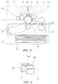
- Fig. 3 is a summary diagram showing a structure of an image forming apparatus in embodiment 1 of the present invention.
- 10 is an electrophotography printer as an image forming apparatus in the embodiment.
- the image forming apparatus it may be a facsimile apparatus with electrophotography, a copying apparatus, a multiple apparatus including facsimile function and copy function or the like.
- the image forming apparatus it may be a facsimile apparatus with electrophotography, a copying apparatus, a multiple apparatus including facsimile function and copy function or the like.
- an electrophotography printer it is to explain an electrophotography printer.
- the electrophotography printer 10 has an image drum cartridge (hereinafter: it is called ID) 11 as an image forming unit; a LED head 12 as an exposing unit; a transferring unit 13 to transfer an toner image onto a medium such as print sheet or the like; a fixing unit 14 to fixing the toner image transferred on the medium; and a sheet supplying unit 15 to accommodate the medium and to supply it.
- ID image drum cartridge
- LED head 12 as an exposing unit
- a transferring unit 13 to transfer an toner image onto a medium such as print sheet or the like
- a fixing unit 14 to fixing the toner image transferred on the medium
- a sheet supplying unit 15 to accommodate the medium and to supply it.
- the ID 11 has a photosensitive drum 16 as an image carrying body which is constructed from an electroconductive basic layer made from Aluminum and an external layer made from an organic photosensitive body; a charging roller 17 obtained through forming a semiconductive rubber such as epichlorohydrin rubber and the like onto a metal shaft with electroconductivity in a roll shape; a developing roller 18 obtained through forming a semiconductive rubber such as silicon an the like onto a metal shaft with electroconductivity; a providing roller 19 obtained through doping a foaming agent into a rubber in a mixed manufacture in order to improve conveyance ability of developer i.e.
- a charging roller 17 obtained through forming a semiconductive rubber such as epichlorohydrin rubber and the like onto a metal shaft with electroconductivity in a roll shape
- a developing roller 18 obtained through forming a semiconductive rubber such as silicon an the like onto a metal shaft with electroconductivity
- a providing roller 19 obtained through doping a foaming agent into a rubber in a mixed manufacture in order to improve conveyanc
- toner and forming the a rubber onto a metal shaft with electroconductivity a developing blade 21 for uniformly forming a thin layer of toner on the developing roller 18; a spacer 22 as a distance limiting member to limit a distance between the LED head 12 and the photosensitive drum 16; and a cleaning roller 23 for shaving a stated below transfer remainder toner 25 remaining on the photosensitive drum 16 after the transferring unit 13 transferred a toner image onto the medium.
- the charging roller 17, the developing roller 18, the spacer 22 and the cleaning roller 23 are furnished as contacting with the surface of the photosensitive drum 16. Further, the developing blade 21 an the providing roller 19 are furnished as contacting with the surface of the developing roller 18. Then, a developing roller power supply, a providing roller supply, a developing blade power supply, a charging unit power supply and a cleaning roller power supply that are not shown respectively connected with the developing roller 18, the providing roller 19, the developing blade 21, the charging roller 17 and the cleaning roller 23 so as to possibly supply bias.
- one end contacts with the LED head 12 which is pressed toward the photosensitive drum 16 by a LED head pressing member 24, and other end contacts with the surface of the photosensitive drum 16.
- Fig. 1 is a squint-eyed diagram showing a spacer furnished in between a LED head and a photosensitive drum in embodiment 1 of the present invention
- Fig. 4 is a squint-eyed diagram showing a summary shape of a spacer in embodiment 1 of the present invention
- Fig. 5 is a squint-eyed diagram showing a shape of underside of a spacer in embodiment 1 of the present invention
- Fig. 6 is a front view diagram showing a spacer furnished in between a LED head and a photosensitive drum in embodiment 1 of the present invention
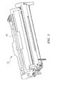
- Fig. 7 is a squint-eyed diagram showing an ID (Image Drum cartridge) on which a cover is installed in embodiment 1 of the present invention
- Fig. 8 is a squint-eyed diagram showing a main part of an ID in which a cover is removed in embodiment 1 of the present invention
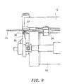
- Fig. 9 is a front view diagram showing a main part of an ID in which a cover is removed in embodiment 1 of the present invention
- Fig. 10 is a diagram showing a state installing a lever in embodiment 1 of the present invention
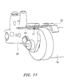
- Fig. 11 is a squint-eyed diagram showing a main part of an ID on which a lever is installed in embodiment 1 of the present invention.
- the spacer 22 has a contact surface 31 contacting with the surface of the photosensitive drum 16.
- the contact surface 31 is desired to be a curvature surface as drawing an arc.
- the contact surface 31 is not limited being a curvature surface, it may also be a surface with V-shape.
- the spacer 22 has a contact surface 33a and a contact surface 33b on reverse side of the contact surface 31.
- the spacer 22 has an upstream side end portion 32 as an image carrying body rotation upstream side end portion which places at an upstream side in a rotation direction of the photosensitive drum 16.
- Fig. 5 shows a state when viewing the spacer 22 from under side.
- C is a length of the spacer 22 in the rotation direction of the photosensitive drum 16.
- the spacer 22 as shown by the Figs. 1 and 6, is furnished between the surface of the photosensitive drum 16 and the LED head 12 to limit a distance between the surface of the photosensitive drum 16 and the LED head 12.
- the contact surface 31 contacts with the surface of the photosensitive drum 16, the contact surface 33a and the contact surface 33b contact with the LED head 12.
- an arrow B indicates a rotation direction of the photosensitive drum 16. Then, a transfer remainder toner 25 accumulates on the upstream side end portion 32 of the spacer 22.
- a lever 34 whose one end is installed on the spacer 22, is furnished as extending in an axis direction of the photosensitive drum 16 and the LED head 12.
- the other end of the lever 34 is projecting toward the outside of an ID frame body 35.
- the Fig. 7 shows the ID 11 of a state in which a cover 20 is installed
- the Figs. 8 and 9 shows the ID 11 of a state in which a cover 20 is removed for simplifying explanation.
- the lever 34 may be formed in a body with the spacer 22.
- the lever 34 is rotatably supported by a lever rotation fulcrum 37 which is installed in the ID frame body 35, and is pressed by a pressing member 36 which is installed in the ID frame body 35 toward a direction, enabling the spacer 22 to contact with the photosensitive drum 16.
- the lever 34 includes a fitted portion 37a which is fitted on the lever rotation fulcrum 37.
- the lever 34 is supported by the lever rotation fulcrum 37.
- a solenoid 38 is installed on the cover 20 of the substance body side of the ID 11.
- a rod of the solenoid 38 expands and contracts to possibly make the other end of the lever 34 move downward, which is opposite to the one end on the spacer 22.
- the charging roller 17 is supplied a high voltage to uniformly afford negative charge to the surface of the photosensitive drum 16.
- the LED head 12 selectively irradiates light energy to the surface of the photosensitive drum 16.
- the electric potential of the part irradiated by the light energy, that is the exposed part falls.
- a difference of surface potential happened. Therefore, on the whole surface of the photosensitive drum 16, an electrostatic latent image is formed. Then, with the rotation of the photosensitive drum 16, the electrostatic latent image moves to the position of the developing roller 18.
- the developing process is to make toner adhere to the electrostatic latent image and to develop the electrostatic latent image into a toner image.
- the toner is charging through friction between the developing roller 18 and the developing blade 21 and friction between the developing roller 18 and the providing roller 19, and through voltages that are respectively supplied to the developing roller 18, the developing blade 21 and the providing roller 19.
- the charging toner moves to the surface of the photosensitive drum 16 in an electric field produced by a difference between the potential of the developing roller 18 and the potential of the surface of the photosensitive drum 16 to form an image.
- the transferring process is to afford positive electric charge to the back face of the medium from the transferring unit 13. Then, the toner negatively charging on the surface of the photosensitive drum 16 is transferred to the medium by a coulomb force. Moreover, the transfer remainder toner 25 as toner which is not transferred to the medium in the transferring process, after shaved by the cleaning roller 23 from the surface of the photosensitive drum 16, is returned to the photosensitive drum 16 and is finally collected by the developing roller 18.
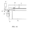
- Fig. 12 is a front view diagram showing a state in which a spacer furnished in between a LED head and a photosensitive drum is lifted up in embodiment 1 of the present invention
- Fig. 13 is a squint-eyed diagram showing a state in which a spacer furnished in between a LED head and a photosensitive drum is lifted up in embodiment 1 of the present invention
- Fig. 14 is a flowchart showing print operation of a printer with electrophotography in embodiment 1 of the present invention.
- the electrophotography printer 10 starts to print after the photosensitive drum 16 rotates. Then, after a print ended, the solenoid 38 is operated.
- the rod of the solenoid 38 expands to provide a load to the lever 34, as shown by the Fig. 12, the other end of the lever 34 moves downward, which is opposite to the one end on the spacer 22 side and is pressed downward by the rod of the solenoid 38.
- the spacer 22 is lifted up together with the LED head 12.
- the spacer 22 and the surface of the photosensitive drum 16 become a separation state, so the transfer remainder toner 25 accumulated on the upstream side end portion 32 of the spacer 22 is left on the photosensitive drum 16.
- the transfer remainder toner 25 gets a friction heat due to the rotation of the photosensitive drum 16.
- the transfer remainder toner 25 liquefies; when the photosensitive drum 16 stops to rotate, the transfer remainder toner 25 is cooled to coagulate, and adheres to the upstream side end portion 32 of the spacer 22.
- the transfer remainder toner 25 adhering to the upstream side end portion 32 of the spacer 22 scrapes the surface of the photosensitive drum 16. Then, if the scrape of the surface of the photosensitive drum 16 arrives in the basic layer with electroconductivity, the voltage provided from the charging roller 17 occurs leak, then the normal charging process can not be executed, and a bad print is caused.
- the load provided by the lever 34 is released through the solenoid 38. Then, through the pressing force of the pressing member 36, the lever 34 clockwise rotates around the lever rotation fulcrum 37 as a center to return to the original position. Therefore, the spacer 22 moves downward together with the LED head 12 to contact with the surface of the photosensitive drum 16. At that time, on the surface of the photosensitive drum 16, the transfer remainder toner 25 does not exist on the part that is contacting with the spacer 22. Then the rotation of the photosensitive drum 16 is stopped.
- the supply of the load to the lever 34 through the solenoid 38 may not be performed per print, for example, it can be performed after executing print of plural sheets. Further, the supply of the load to the lever 34 through the solenoid 38 may not be performed after print, for example, it can be performed when print is not executed but the photosensitive drum 16 is rotating for warming up executed after plugging in the electrophotography printer 10 or when a printer cover is shut from an opening state or the like.
- the embodiment makes spacer 22 separate from a contact state with the surface of the photosensitive drum 16, and makes the transfer remainder toner 25 accumulated on the upstream side end portion 32 of the spacer 22 moves.
- the transfer remainder toner 25 does not adhere to the upstream side end portion 32 of the spacer 22, it is eliminated that the surface of the photosensitive drum 16 is scraped. Therefore, it is possible to execute a normal charging process, and to prevent a bad print from happening.
- Fig. 15 is a diagram showing a spacer and a cleaning blade furnished in between a LED head and a photosensitive drum is lifted up in embodiment 2 of the present invention
- Fig. 16 is a first squint-eyed diagram showing a spacer and a cleaning blade furnished in between a LED head and a photosensitive drum is lifted up in embodiment 2 of the present invention
- Fig. 17 is a second squint-eyed diagram showing a spacer and a cleaning blade furnished in between a LED head and a photosensitive drum is lifted up in embodiment 2 of the present invention.
- a cleaning blade 41 is furnished as a cleaning member made of Urethane gom.
- the cleaning blade 41 is pressed to contact with the surface of the photosensitive drum 16.
- a width E of the cleaning blade 41 in an axis direction of the photosensitive drum 16 is formed as being wider than a width D of the spacer 22.
- the material of the cleaning blade 41 may be any one kind if only possibly shaving the transfer remainder toner 25, for example, it may be made from Urethane sponge, Teflon felt or the like.
- the cleaning blade 41 may be formed in one body with the spacer 22 through a fixation means, the fixation means may be to perform a fixation using adhesiveness, also may be to perform a heat weld.
- the furnished position of the cleaning blade 41 is at upstream side of the spacer 22 in the rotation direction of the photosensitive drum 16, it may be anywhere if only being at downstream side of the charging roller 17 in the rotation direction of the photosensitive drum 16, further it may be apart from the spacer 22.
- the cleaning blade 41 is installed on the spacer 22, it may also be installed in the inside of the unit 11.
- a cleaning blade 42 also can be used with a shape shown by the Fig. 17.
- the cleaning blade 42 is formed as that the part pressed and contacted to the surface of the photosensitive drum 16 inclines with respect to the axis direction of the photosensitive drum 16. That is, in the cleaning blade 42, if the width E in the axis direction of the photosensitive drum 16 is wider than the width D of the spacer 22, the part pressed and contacted to the surface of the photosensitive drum 16 may incline with respect to the axis direction of the photosensitive drum 16. Moreover, the inclination direction may be toward the inside of the ID 11 from the outside; also may be toward the outside of the ID 11 from the inside.
- the toner in the case that the inclination direction is toward the outside, the toner maybe move to out of an area of the cleaning roller 23, then the toner is not cleaned. Therefore, it is desired that the inclination direction is toward the inside. Thus, the toner which is made move to the inside is easily cleaned by the cleaning roller 23.
- the photosensitive drum 16 rotates along a direction indicated by an arrow B.
- the transfer remainder toner 25 on the surface of the photosensitive drum 16 arrived at the cleaning blade 41, the transfer remainder toner 25 is stopped by the cleaning blade 41.
- the width E of the cleaning blade 41 in the axis direction of the photosensitive drum 16 is wider than the width D of the spacer 22, the transfer remainder toner 25 at least does not arrive in a range of the width D of the spacer 22. Therefore, the transfer remainder toner 25 does not accumulate on the upstream side end portion 32 of the spacer 22.
- a contact point of the cleaning blade 41 and the photosensitive drum 16 is perpendicularly closer to the upstream side of the rotation direction of the photosensitive drum 16 than a contact point of the spacer 22 and the photosensitive drum 16, the toner easily falls downward without accumulating.
- the cleaning blade 41 shaves the transfer remainder toner 25 on the surface of the photosensitive drum 16. Because the transfer remainder toner 25 does not arrive at the spacer 22, so the transfer remainder toner 25 does not accumulate on the upstream side end portion 32 of the spacer 22. Therefore, because the transfer remainder toner 25 does not adhere to the upstream side end portion 32 of the spacer 22, it is eliminated that the surface of the photosensitive drum 16 is scraped, and it is possible to execute a normal charging process and to prevent a bad print from happening.
- Fig. 18 is a squint-eyed diagram showing a summary shape of a spacer in embodiment 3 of the present invention
- Fig. 19 is a squint-eyed diagram showing a underside shape of a spacer in embodiment 3 of the present invention
- Fig. 20 is a diagram showing an incline angle of an upstream side end portion in embodiment 3 of the present invention
- Fig. 21 is a diagram showing an incline direction of an upstream side end portion in embodiment 3 of the present invention.
- a spacer 51 as a distance limiting member as shown by the Fig. 18, has a contact surface 52 contacting with the surface of the photosensitive drum 16.
- the contact surface 52 is desired to be a curvature surface as drawing an arc.
- the contact surface 52 is not limited being a curvature surface, it may also be a surface with V-shape.
- the spacer 51 has a contact surface 55a and a contact surface 55b on reverse side of the contact surface 52.
- the spacer 51 has an upstream side end portion 53 as an image carrying body rotation upstream side end portion which places at an upstream side in a rotation direction of the photosensitive drum 16.
- Fig. 19 shows a state when viewing the spacer 51 from under side.
- the upstream side end portion 53 inclines toward the inside of the ID 11 from the outside with respect to the rotation direction of the photosensitive drum 16.
- the spacer 51 is furnished as that a downstream end portion 56 in the upstream side end portion 53 in the rotation direction of the photosensitive drum 16 places at the outside of the ID 11 out of a printable medium with a maximum width.
- an inclination angle ⁇ of the upstream side end portion 53 is desired to be less than 60 degrees so as to make the transfer remainder toner 25 can smoothly move along the upstream side end portion 53.
- the upstream side end portion 53, with respect to the rotation direction of the photosensitive drum 16, may be formed as inclining toward the outside of the ID 11 from the inside of the ID 11; and also may be formed as inclining toward two directions as shown by the Fig. 21.
- the toner maybe move to out of an area of the cleaning roller 23, then the toner is not cleaned. Therefore, it is desired that the inclination direction is toward the inside. Thus, the toner made move to the inside is easily cleaned by the cleaning roller 23.
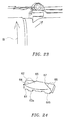
- Fig. 22 is a squint-eyed diagram showing a spacer furnished in between a LED head and a photosensitive drum in embodiment 3 of the present invention
- Fig. 23 is a magnification diagram showing a main part of a spacer furnished in between a LED head and a photosensitive drum in embodiment 3 of the present invention.
- the transfer remainder toner 25 moves to the downstream side of the rotation direction of the photosensitive drum 16 from the outside of the ID 11 to the inside of the ID 11.
- the transfer remainder toner 25 is not scraped by the upstream side end portion 53 of the spacer 51, so the transfer remainder toner 25 does not accumulate on the upstream side end portion 53 of the spacer 51.
- the transfer remainder toner 25 on the photosensitive drum 16 even if arrived at the upstream side end portion 53 of the spacer 51, because moving along the inclining upstream side end portion 53, so does not accumulate on the upstream side end portion 53.
- the transfer remainder toner 25 does not adhere to the upstream side end portion 53 of the spacer 51, it is eliminated that the surface of the photosensitive drum 16 is scraped, and it is possible to execute a normal charging process and to prevent a bad print from happening.
- a machinery to make the spacer 51 contact with and separate from the surface of the photosensitive drum 16 and the cleaning blade 41 are left out, it is possible to improve the assembling ability of the ID 11, and to reduce the parts number of the ID 11.
- Fig. 24 is a squint-eyed diagram showing an underside shape of a spacer in embodiment 4 of the present invention
- Fig. 25 is a diagram showing an incline angle of an upstream side end portion and a downstream side end portion in embodiment 4 of the present invention
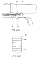
- Fig. 26A is a first diagram showing an incline direction of an upstream side end portion and a downstream side end portion in embodiment 4 of the present invention
- Fig. 26B is a second diagram showing an incline direction of an upstream side end portion and a downstream side end portion in embodiment 4 of the present invention
- Fig. 27 is a diagram showing a method to mount a spacer in embodiment 4 of the present invention.
- a spacer 61 as a distance limiting member has a contact surface 62 contacting with the surface of the photosensitive drum 16.
- the contact surface 62 is desired to be a curvature surface as drawing an arc.
- the contact surface 62 is not limited being a curvature surface, it may also be a surface with V-shape.
- the spacer 61 has a contact surface 63a and a contact surface 63b on reverse side of the contact surface 62.
- the spacer 61 has an upstream side end portion 64 as an image carrying body rotation upstream side end portion which places at an upstream side in a rotation direction of the photosensitive drum 16, and a downstream side end portion 66 as an image carrying body rotation downstream side end portion which places at a downstream side in a rotation direction of the photosensitive drum 16.
- the upstream side end portion 64 inclines toward the inside of the ID 11 from the outside of the ID 11 with respect to the rotation direction of the photosensitive drum 16. Then, the spacer 61 is furnished as that a downstream end portion 65 in the upstream side end portion 64 in the rotation direction of the photosensitive drum 16 places at the outside of the ID 11 out of a printable medium with a maximum width.
- an inclination angle ⁇ 1 of the upstream side end portion 64 is desired to be less than 60 degrees so as to make the transfer remainder toner 25 can smoothly move along the upstream side end portion 64.
- the upstream side end portion 64, with respect to the rotation direction of the photosensitive drum 16, may be formed as inclining toward the outside of the ID 11 from the inside of the ID 11; also may be formed as inclining toward two directions as shown by the Fig. 26A; and also may be formed as inclining toward one direction as shown by the Fig. 26B.
- the upstream side end portion 66 inclines toward the outside of the ID 11 from the inside of the ID 11 with respect to the rotation direction of the photosensitive drum 16. Then, the spacer 61 is furnished as that an upstream end portion 67 in the downstream side end portion 66 in the rotation direction of the photosensitive drum 16 places at the outside of the ID 11 out of a printable medium with a maximum width.
- an inclination angle ⁇ 2 of the downstream side end portion 66 is desired to be less than 60 degrees so as to make the transfer remainder toner 25 can smoothly move along the downstream side end portion 66.
- the downstream side end portion 66, with respect to the rotation direction of the photosensitive drum 16, may be formed as inclining toward the inside of the ID 11 from the outside of the ID 11; also may be formed as inclining toward two directions as shown by the Fig. 26.
- the spacer 61 is respectively furnished on the two ends of the photosensitive drum 16. Moreover, the spacer 61 of left side serves as a left side spacer 61a, and the spacer 61 of right side serves as a right side spacer 61b. in the case, spacer contact portions 67a and 67b of left and right of the LED head 12 are different. Further, the left side spacer 61a and the right side spacer 61b are installed as they are opposite each other.
- Fig. 28 is a diagram showing an interference of a spacer and a LED head in embodiment 4 of the present invention
- Fig. 29 is a diagram showing a state in which an interference of a spacer and a LED head is cancelled in embodiment 4 of the present invention.
- Fig. 28A is a main part magnification squint-eyed diagram
- Fig. 28B is an upside diagram of spacer.
- the spacer contact portion 67a of left side of the LED head 12 contacts with the left side spacer 61a, but because the spacer contact portion 67b of right side of the LED head 12 is different from the spacer contact portion 67a, if installing the right side spacer 61b in a same direction as the left side spacer 61a, as shown by the Fig. 28, an interference happened in an interference portion 68. Therefore, as shown by the Fig. 29, the right side spacer 61b is furnished through changing its direction so as to release the interference. Thus, the spacer contact portion 67b of right and the right side spacer 61b contact each other without interfering.
- the downstream side end portion 66 of the right side spacer 61b becomes to place at an upstream side in the rotation direction of the photosensitive drum 16. Because of this, after the photosensitive drum 16 rotates and the transfer remainder toner 25 on the photosensitive drum 16 arrived at the downstream side end portion 66 of the spacer 61b, the transfer remainder toner 25, along the inclining downstream side end portion 66, moves to the downstream side of the rotation direction of the photosensitive drum 16 from the outside of the ID 11 to the inside of the ID 11. At that time, because the transfer remainder toner 25 is not scraped by the downstream side end portion 66 of the spacer 61b, so the transfer remainder toner 25 does not accumulate on the downstream side end portion 66 of the spacer 61b.
- the upstream side end portion 64 of the right side spacer 61a places at an upstream side in the rotation direction of the photosensitive drum 16. Because of this, after the photosensitive drum 16 rotates and the transfer remainder toner 25 arrived at the upstream side end portion 64 of the spacer 61a, the transfer remainder toner 25, along the inclining upstream side end portion 64, as indicated by an arrow F, moves to the downstream side of the rotation direction of the photosensitive drum 16 from the outside of the ID 11 to the inside of the ID 11. At that time, because the transfer remainder toner 25 is not scraped by the upstream side end portion 64 of the spacer 61a, so the transfer remainder toner 25 does not accumulate on the upstream side end portion 64 of the spacer 61a.
- the transfer remainder toner 25 on the photosensitive drum 16 even if arrived at the upstream side end portion 64 of the left side spacer 61a, because moving along the inclining upstream side end portion 64, so does not accumulate on the upstream side end portion 64.
- the transfer remainder toner 25 does not adhere to the upstream side end portion 64 of the left side spacer 61a, it is eliminated that the surface of the photosensitive drum 16 is scraped.
- the transfer remainder toner 25 on the photosensitive drum 16 even if arrived at the downstream side end portion 66 of the right side spacer 61b, because moving along the inclining downstream side end portion 66, so does not accumulate on, the downstream side end portion 66.
- the transfer remainder toner 25 does not adhere to the downstream side end portion 66 of the right side spacer 61b, it is eliminated that the surface of the photosensitive drum 16 is scraped.
- An image forming unit in which, through making a distance limiting member to limit a distance between an exposing unit and an image carrying body be able to contact and separate with respect to the image carrying body by a contact/separation enabling section, it is eliminated that developer remaining on the surface of the image carrying body coagulates on the distance limiting member, so it is eliminated that the surface of the image carrying body is scraped by the developer, and that a bad print occurs.
- the image forming unit has an image carrying body exposed by an exposing unit, a distance limiting member to limit a distance between the exposing unit and the image carrying body.
- the distance limiting member is installed capable of contacting with and separating from the image carrying body by a contact/separation enabling section.
Landscapes
- Physics & Mathematics (AREA)
- General Physics & Mathematics (AREA)
- Electrophotography Configuration And Component (AREA)
- Cleaning In Electrography (AREA)
- Discharging, Photosensitive Material Shape In Electrophotography (AREA)
- Printers Or Recording Devices Using Electromagnetic And Radiation Means (AREA)
- Exposure Or Original Feeding In Electrophotography (AREA)
- Electrostatic Charge, Transfer And Separation In Electrography (AREA)
Applications Claiming Priority (1)
| Application Number | Priority Date | Filing Date | Title |
|---|---|---|---|
| JP2005263478A JP2007076031A (ja) | 2005-09-12 | 2005-09-12 | 画像形成ユニット及び画像形成装置 |
Publications (2)
| Publication Number | Publication Date |
|---|---|
| EP1762904A2 true EP1762904A2 (de) | 2007-03-14 |
| EP1762904A3 EP1762904A3 (de) | 2009-06-03 |
Family
ID=37561148
Family Applications (1)
| Application Number | Title | Priority Date | Filing Date |
|---|---|---|---|
| EP06119675A Withdrawn EP1762904A3 (de) | 2005-09-12 | 2006-08-29 | Bilderzeugungseinheit und Bilderzeugungsapparat |
Country Status (4)
| Country | Link |
|---|---|
| US (1) | US7777769B2 (de) |
| EP (1) | EP1762904A3 (de) |
| JP (1) | JP2007076031A (de) |
| CN (1) | CN1932670B (de) |
Cited By (1)
| Publication number | Priority date | Publication date | Assignee | Title |
|---|---|---|---|---|
| EP2685324A1 (de) * | 2012-05-24 | 2014-01-15 | Kyocera Document Solutions Inc. | Reinigungsvorrichtung und Bilderzeugungsvorrichtung mit Reinigungsvorrichtung |
Families Citing this family (14)
| Publication number | Priority date | Publication date | Assignee | Title |
|---|---|---|---|---|
| US8289359B2 (en) * | 2008-06-30 | 2012-10-16 | Brother Kogyo Kabshiki Kaisha | Image forming apparatus and method of manufacturing the same |
| JP5263322B2 (ja) * | 2011-03-10 | 2013-08-14 | ブラザー工業株式会社 | 画像形成装置 |
| JP5867075B2 (ja) * | 2011-12-28 | 2016-02-24 | ブラザー工業株式会社 | 画像形成装置および現像ユニット |
| JP6210366B2 (ja) * | 2013-07-31 | 2017-10-11 | 株式会社リコー | 付着物除去機構、プロセスカートリッジ、及び画像形成装置 |
| JP6241738B2 (ja) | 2013-07-31 | 2017-12-06 | 株式会社リコー | 光書込ヘッド位置決め機構、プロセスカートリッジ、及び画像形成装置 |
| JP6241602B2 (ja) * | 2013-10-24 | 2017-12-06 | 株式会社リコー | プロセスユニット、画像形成装置 |
| JP6394938B2 (ja) * | 2014-04-21 | 2018-09-26 | 株式会社リコー | 光書込ヘッド位置決め機構、プロセスユニット及び画像形成装置 |
| JP6344553B2 (ja) * | 2014-05-07 | 2018-06-20 | 株式会社リコー | 光書込ヘッド位置決め機構、プロセスユニット及び画像形成装置 |
| JP2016022716A (ja) * | 2014-07-24 | 2016-02-08 | 株式会社リコー | 光書込ヘッド位置決め機構、画像形成装置 |
| US9772601B2 (en) * | 2015-07-29 | 2017-09-26 | Ricoh Company, Ltd. | Image forming apparatus and process unit |
| JP6617921B2 (ja) * | 2015-07-29 | 2019-12-11 | 株式会社リコー | 感光体の異物除去機構、プロセスユニット及び画像形成装置 |
| JP6826775B2 (ja) | 2016-10-25 | 2021-02-10 | 株式会社リコー | 画像形成装置 |
| JP7225990B2 (ja) * | 2019-03-22 | 2023-02-21 | 富士フイルムビジネスイノベーション株式会社 | 画像形成装置 |
| CN117666308A (zh) * | 2022-09-08 | 2024-03-08 | 华为技术有限公司 | 打印机 |
Citations (3)
| Publication number | Priority date | Publication date | Assignee | Title |
|---|---|---|---|---|
| JPS53104242A (en) | 1977-02-24 | 1978-09-11 | Ricoh Co Ltd | Recorder |
| US4703334A (en) | 1983-08-26 | 1987-10-27 | Ricoh Company, Ltd. | Optical recording head and belt positioning apparatus |
| US20020149664A1 (en) | 2001-04-06 | 2002-10-17 | Oki Data Corporation | Optical head positioning apparatus |
Family Cites Families (7)
| Publication number | Priority date | Publication date | Assignee | Title |
|---|---|---|---|---|
| JPS5850845A (ja) * | 1981-09-11 | 1983-03-25 | Toyota Motor Corp | 車両用制御装置の制御タ−ミナル間の通信方法 |
| JPH02188776A (ja) * | 1989-01-18 | 1990-07-24 | Mitsubishi Electric Corp | 電子写真記録装置 |
| JPH0635290A (ja) * | 1992-07-20 | 1994-02-10 | Fuji Xerox Co Ltd | 画像形成装置 |
| JP2001142368A (ja) * | 1999-11-11 | 2001-05-25 | Kyocera Mita Corp | 有機感光体ドラムのクリーニング方法 |
| JP4073234B2 (ja) * | 2001-04-06 | 2008-04-09 | 株式会社沖データ | 光学式ヘッドの位置決め装置、ledヘッドの位置決め装置、及び印刷装置 |
| US7154525B2 (en) * | 2002-06-26 | 2006-12-26 | Sharp Kabushiki Kaisha | Method and device for focus adjustment of optical writing unit and image forming apparatus incorporating the focus adjustment device |
| JP2006018126A (ja) * | 2004-07-05 | 2006-01-19 | Murata Mach Ltd | 画像形成装置 |
-
2005
- 2005-09-12 JP JP2005263478A patent/JP2007076031A/ja active Pending
-
2006
- 2006-08-28 CN CN200610129006.4A patent/CN1932670B/zh not_active Expired - Fee Related
- 2006-08-29 EP EP06119675A patent/EP1762904A3/de not_active Withdrawn
- 2006-08-31 US US11/513,135 patent/US7777769B2/en not_active Expired - Fee Related
Patent Citations (3)
| Publication number | Priority date | Publication date | Assignee | Title |
|---|---|---|---|---|
| JPS53104242A (en) | 1977-02-24 | 1978-09-11 | Ricoh Co Ltd | Recorder |
| US4703334A (en) | 1983-08-26 | 1987-10-27 | Ricoh Company, Ltd. | Optical recording head and belt positioning apparatus |
| US20020149664A1 (en) | 2001-04-06 | 2002-10-17 | Oki Data Corporation | Optical head positioning apparatus |
Cited By (2)
| Publication number | Priority date | Publication date | Assignee | Title |
|---|---|---|---|---|
| EP2685324A1 (de) * | 2012-05-24 | 2014-01-15 | Kyocera Document Solutions Inc. | Reinigungsvorrichtung und Bilderzeugungsvorrichtung mit Reinigungsvorrichtung |
| US9002221B2 (en) | 2012-05-24 | 2015-04-07 | Kyocera Document Solutions Inc. | Cleaning device for image carrier and image forming apparatus including cleaning portion for image carrier |
Also Published As
| Publication number | Publication date |
|---|---|
| CN1932670A (zh) | 2007-03-21 |
| US7777769B2 (en) | 2010-08-17 |
| US20070064082A1 (en) | 2007-03-22 |
| CN1932670B (zh) | 2014-07-09 |
| EP1762904A3 (de) | 2009-06-03 |
| JP2007076031A (ja) | 2007-03-29 |
Similar Documents
| Publication | Publication Date | Title |
|---|---|---|
| US7777769B2 (en) | Image forming unit and image forming apparatus | |
| US4264191A (en) | Electrophotographic imaging system including a laminated cleaning and/or doctor blade | |
| EP2169478A1 (de) | Bilderzeugungsvorrichtung mit verbesserter Gehäuseplattenstrukturstärke | |
| US20130051840A1 (en) | Electrophotographic image forming apparatus and process cartridge | |
| US8929795B2 (en) | Cleaning device, process cartridge and image forming apparatus | |
| JPH08137357A (ja) | 画像形成装置 | |
| US5940661A (en) | Image forming apparatus with a charging member which removes smears on an image forming member | |
| JP3765341B2 (ja) | クリーナ装置 | |
| JP2000181221A (ja) | 画像形成装置 | |
| JP5155970B2 (ja) | 画像形成装置 | |
| US7970319B2 (en) | Charging apparatus, print engine that incorporates the charging apparatus, and image forming apparatus that incorporates the print engine | |
| JP4740669B2 (ja) | クリーニング装置を備えた画像形成装置 | |
| US20060210321A1 (en) | Developing unit and image forming apparatus | |
| US11520275B2 (en) | Cleaning device capable of suppressing that a sealing member constitutes a resistance to a rotational operation of a supporting member for a cleaning blade | |
| JPH08202225A (ja) | ローラクリーニング装置 | |
| JP4517658B2 (ja) | 現像装置 | |
| JP2010020296A (ja) | 画像形成装置及びクリーナ装置 | |
| JP2003208068A (ja) | 像担持体クリーニング装置及び該装置を備えた画像形成装置 | |
| JP6645266B2 (ja) | クリーニング装置及び画像形成装置 | |
| JP3317044B2 (ja) | クリーニング装置 | |
| JP4247058B2 (ja) | 現像装置 | |
| JP5545538B2 (ja) | 転写装置及び画像形成装置 | |
| KR100608022B1 (ko) | 정착장치를 구비한 화상형성장치 | |
| JPH10268669A (ja) | 画像形成装置 | |
| JP2002132051A (ja) | 分離部材及びプロセスカートリッジ及び画像形成装置 |
Legal Events
| Date | Code | Title | Description |
|---|---|---|---|
| PUAI | Public reference made under article 153(3) epc to a published international application that has entered the european phase |
Free format text: ORIGINAL CODE: 0009012 |
|
| AK | Designated contracting states |
Kind code of ref document: A2 Designated state(s): AT BE BG CH CY CZ DE DK EE ES FI FR GB GR HU IE IS IT LI LT LU LV MC NL PL PT RO SE SI SK TR |
|
| AX | Request for extension of the european patent |
Extension state: AL BA HR MK YU |
|
| PUAL | Search report despatched |
Free format text: ORIGINAL CODE: 0009013 |
|
| AK | Designated contracting states |
Kind code of ref document: A3 Designated state(s): AT BE BG CH CY CZ DE DK EE ES FI FR GB GR HU IE IS IT LI LT LU LV MC NL PL PT RO SE SI SK TR |
|
| AX | Request for extension of the european patent |
Extension state: AL BA HR MK RS |
|
| RIC1 | Information provided on ipc code assigned before grant |
Ipc: G03G 15/04 20060101AFI20070108BHEP Ipc: G03G 15/32 20060101ALI20090424BHEP |
|
| 17P | Request for examination filed |
Effective date: 20091203 |
|
| 17Q | First examination report despatched |
Effective date: 20100107 |
|
| AKX | Designation fees paid |
Designated state(s): DE FR GB NL |
|
| STAA | Information on the status of an ep patent application or granted ep patent |
Free format text: STATUS: THE APPLICATION IS DEEMED TO BE WITHDRAWN |
|
| 18D | Application deemed to be withdrawn |
Effective date: 20170301 |