EP1763396B1 - Vorrichtung und verfahren zum begasen von flüssigkeiten, insbesondere abwasser - Google Patents
Vorrichtung und verfahren zum begasen von flüssigkeiten, insbesondere abwasser Download PDFInfo
- Publication number
- EP1763396B1 EP1763396B1 EP05757160A EP05757160A EP1763396B1 EP 1763396 B1 EP1763396 B1 EP 1763396B1 EP 05757160 A EP05757160 A EP 05757160A EP 05757160 A EP05757160 A EP 05757160A EP 1763396 B1 EP1763396 B1 EP 1763396B1
- Authority
- EP
- European Patent Office
- Prior art keywords
- gassing
- gas supply
- supply line
- liquid
- rivets
- Prior art date
- Legal status (The legal status is an assumption and is not a legal conclusion. Google has not performed a legal analysis and makes no representation as to the accuracy of the status listed.)
- Expired - Lifetime
Links
Images



Classifications
-
- B—PERFORMING OPERATIONS; TRANSPORTING
- B01—PHYSICAL OR CHEMICAL PROCESSES OR APPARATUS IN GENERAL
- B01F—MIXING, e.g. DISSOLVING, EMULSIFYING OR DISPERSING
- B01F23/00—Mixing according to the phases to be mixed, e.g. dispersing or emulsifying
- B01F23/20—Mixing gases with liquids
- B01F23/23—Mixing gases with liquids by introducing gases into liquid media, e.g. for producing aerated liquids
- B01F23/231—Mixing gases with liquids by introducing gases into liquid media, e.g. for producing aerated liquids by bubbling
- B01F23/23105—Arrangement or manipulation of the gas bubbling devices
- B01F23/2311—Mounting the bubbling devices or the diffusers
-
- B—PERFORMING OPERATIONS; TRANSPORTING
- B01—PHYSICAL OR CHEMICAL PROCESSES OR APPARATUS IN GENERAL
- B01F—MIXING, e.g. DISSOLVING, EMULSIFYING OR DISPERSING
- B01F23/00—Mixing according to the phases to be mixed, e.g. dispersing or emulsifying
- B01F23/20—Mixing gases with liquids
- B01F23/23—Mixing gases with liquids by introducing gases into liquid media, e.g. for producing aerated liquids
- B01F23/231—Mixing gases with liquids by introducing gases into liquid media, e.g. for producing aerated liquids by bubbling
- B01F23/23105—Arrangement or manipulation of the gas bubbling devices
- B01F23/2311—Mounting the bubbling devices or the diffusers
- B01F23/23114—Mounting the bubbling devices or the diffusers characterised by the way in which the different elements of the bubbling installation are mounted
- B01F23/231142—Mounting the gas transporting elements, i.e. connections between conduits
-
- B—PERFORMING OPERATIONS; TRANSPORTING
- B01—PHYSICAL OR CHEMICAL PROCESSES OR APPARATUS IN GENERAL
- B01F—MIXING, e.g. DISSOLVING, EMULSIFYING OR DISPERSING
- B01F23/00—Mixing according to the phases to be mixed, e.g. dispersing or emulsifying
- B01F23/20—Mixing gases with liquids
- B01F23/23—Mixing gases with liquids by introducing gases into liquid media, e.g. for producing aerated liquids
- B01F23/231—Mixing gases with liquids by introducing gases into liquid media, e.g. for producing aerated liquids by bubbling
- B01F23/23105—Arrangement or manipulation of the gas bubbling devices
- B01F23/2311—Mounting the bubbling devices or the diffusers
- B01F23/23114—Mounting the bubbling devices or the diffusers characterised by the way in which the different elements of the bubbling installation are mounted
- B01F23/231143—Mounting the bubbling elements or diffusors, e.g. on conduits, using connecting elements; Connections therefor
-
- B—PERFORMING OPERATIONS; TRANSPORTING
- B01—PHYSICAL OR CHEMICAL PROCESSES OR APPARATUS IN GENERAL
- B01F—MIXING, e.g. DISSOLVING, EMULSIFYING OR DISPERSING
- B01F23/00—Mixing according to the phases to be mixed, e.g. dispersing or emulsifying
- B01F23/20—Mixing gases with liquids
- B01F23/23—Mixing gases with liquids by introducing gases into liquid media, e.g. for producing aerated liquids
- B01F23/231—Mixing gases with liquids by introducing gases into liquid media, e.g. for producing aerated liquids by bubbling
- B01F23/23105—Arrangement or manipulation of the gas bubbling devices
- B01F23/2312—Diffusers
- B01F23/23123—Diffusers consisting of rigid porous or perforated material
-
- B—PERFORMING OPERATIONS; TRANSPORTING
- B01—PHYSICAL OR CHEMICAL PROCESSES OR APPARATUS IN GENERAL
- B01F—MIXING, e.g. DISSOLVING, EMULSIFYING OR DISPERSING
- B01F23/00—Mixing according to the phases to be mixed, e.g. dispersing or emulsifying
- B01F23/20—Mixing gases with liquids
- B01F23/23—Mixing gases with liquids by introducing gases into liquid media, e.g. for producing aerated liquids
- B01F23/231—Mixing gases with liquids by introducing gases into liquid media, e.g. for producing aerated liquids by bubbling
- B01F23/23105—Arrangement or manipulation of the gas bubbling devices
- B01F23/2312—Diffusers
- B01F23/23126—Diffusers characterised by the shape of the diffuser element
- B01F23/231265—Diffusers characterised by the shape of the diffuser element being tubes, tubular elements, cylindrical elements or set of tubes
-
- B—PERFORMING OPERATIONS; TRANSPORTING
- B01—PHYSICAL OR CHEMICAL PROCESSES OR APPARATUS IN GENERAL
- B01F—MIXING, e.g. DISSOLVING, EMULSIFYING OR DISPERSING
- B01F2101/00—Mixing characterised by the nature of the mixed materials or by the application field
- B01F2101/305—Treatment of water, waste water or sewage
Definitions
- the invention relates to a device for gassing liquids, in particular wastewater, according to the preamble of claim 1. It further relates to a method for producing such a device.
- Such a device is from the EP-A-1 358 928 known.
- connection nozzles for connecting ventilation arms are disposed of on a ventilation duct.
- the connecting pieces are designed so that the ventilation arms made of sheet metal can be inserted therein.
- the US 5,538,293 describes a ventilation device for distributing air in a building. Aeration ducts branching off from a ventilation duct are inserted into a passage provided in the ventilation duct and latched.
- a device in which a gas supply line is received by clamping in fixed to the bottom of a Klärbekkens clamps.
- a gassing element placed on the gas supply line is fastened with a bolt extending from the clamp through the gas supply line and the gassing element and with a nut screwed thereon.
- the attachment of the gassing disadvantageously requires the provision of the aforementioned clamps.
- the clamps must first be mounted in a predetermined arrangement at the bottom of a clarifier at a cost and time.
- a ventilation element having a longitudinal axis known for connection to a gas supply line is provided with a conical threaded nipple.
- the provision of such a threaded nipple is expensive.
- the threaded nipple must be manufactured separately and welded on for connection to the gassing element.
- For mounting also applied to the thread sealant is required to ensure in the correct mounting position a tight connection between the gassing and the Gaszu Switzerlandrohr.
- the object of the invention is to eliminate the disadvantages of the prior art.
- a device for gassing liquids is to be specified, which is as easy as possible to manufacture and assemble.
- a method for mounting the device is provided, which is simple and quick to carry out.
- the gassing element has two ventilation arms, wherein at least one ventilation tab is provided on each of the ventilation arms.
- the inventively provided fastening tab allows a simple way using conventional fasteners a non-positive connection of the gassing on the gas supply. The assembly of the device is simplified and accelerated. This can save costs for the provision of labor.
- the fastening tab rests positively in the fastening state on the gas supply, prevents uncontrolled gas escapes in the mounting area.
- the gas supplied through the gas supply line is substantially completely introduced into the gassing element connected thereto.
- the gassing element is made in one piece from a metal sheet.
- the sheet may be a stainless steel sheet.
- a suitable contour can first be cut out of the metal sheet and then subsequently bent so that the gassing element results. Eventually formed during bending overlapping walls can then be frictionally connected to each other by the provision of fasteners, such as rivets.
- fasteners such as rivets.
- the fastening tab is a manufactured by bending sheet metal section.
- the sheet metal section is expediently at an angle of 80 to 100 °, advantageously 90 ° with respect to the longitudinal axis of the gassing element, bent.
- the production of such a fastening tab is particularly simple. It is in this case part of the integrally produced from a sheet gassing element.
- the gassing element is fastened to the gas supply line by means of the fastening lug of cross-fastening elements.
- the fasteners may be rivets, screw rivets, screws or the like. Act. Such fasteners, in particular rivets, can be quickly and easily attached to the production of a non-positive connection.
- first openings may be provided for performing the fasteners.
- corresponding second openings for passing through the fastening elements can be provided in the gas supply line to the first openings.
- the first and second breakthroughs can be made by laser cutting the sheet.
- ventilation openings provided in the gassing element are circular, oval, angular or slot-shaped. If the vent openings are formed angular, so they can be designed in the form of triangles, squares, pentagons, hexagons and other types of polygons.
- the opening area of the ventilation openings may decrease with increasing distance from the gas supply line. The opening area is expediently chosen in each case such that a uniform introduction of gas takes place over the entire length of the ventilation element into the liquid.
- a cross-sectional area running perpendicular to the longitudinal axis of the gassing element decreases with increasing distance from the gas supply line. This measure also serves to ensure a uniform possible gas entry into the liquid over the entire length of the gassing element.
- the opening surface of the ventilation apertures provided in the gassing element may increase from top to bottom. Ie. an upper row of vent apertures has a smaller opening area than an underlying further row of vent apertures.
- the two aeration arms having gassing element may be formed symmetrically. When mounting to the gas supply line, the weight distribution is balanced.
- the proposed embodiment is particularly durable and durable.
- each of the ventilation arms has a plurality of attachment tabs, for example two vertical and one horizontal attachment tab.
- the gassing element with the two ventilation arms is designed such that it can be plugged onto the gas supply line in a form-fitting manner with the fastening straps. This facilitates the assembly.
- grooves or webs may be integrally formed on the attachment tabs, which cooperate with corresponding thereto provided on the Gaszu920 ein webs or grooves such that the first provided in the mounting tabs openings are aligned in the plugged state of the fastener to the second in the Gaszu melt slaughter. This further simplifies assembly.
- a method for mounting the device according to the invention is provided with the following steps:
- the proposed method enables a simple and quick installation of the gassing element on the gas supply line.
- the gassing can be quickly and easily attached to the gassing line, for example by means of rivets quickly and easily. It has surprisingly been found that a device produced by the proposed assembly method has excellent mechanical stability and is particularly durable in practical use.
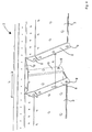
- a plurality of gassing elements 2 are connected to a gas supply line 1 having a substantially rectangular cross-section.
- the gassing elements 2 shown are formed symmetrically and each have two ventilation arms 3.
- the gas supply line 1 has in each case in the connection region of the gassing elements 2 opposite gassing openings (not shown here) through which the gas supplied through the gas supply line 1 reaches the gassing elements 2.
- the gassing element 2 is made in one piece from a, preferably stainless, sheet by bending. At the end faces overlapping first sheet sections 4 and overlapping in the bottom area second sheet metal sections 5 are connected to each other by means of first rivets 6 frictionally.
- the bottom of the ventilation arms 3 must not be formed closed; he may have openings.
- the ventilation element has ventilation openings 7.
- the ventilation openings 7 may be circular, oval or slit-shaped.
- the gassing element 2 in a connection region on each of the gassing arms 3 laterally from a longitudinal axis L of the gassing 2 extending fastening tabs 8.
- the fastening tabs 8 are provided with first openings 9.
- the fastening tabs 8 are made here in one piece with the gassing element 2 by bending by about 90 ° to the outside. A distance A between two mutually opposite attachment tabs 8 is selected so that it corresponds to a width B of the gas supply line 1 substantially.
- the fastening tabs 8 are just as well as the walls of the gas supply 1 formed flat. As a result, the fastening element 2 can be positively plugged onto the gas supply line 1. When plugged in, ventilation openings (not shown here) are completely covered by the ventilation element 2.
- the fastening tabs 8 are non-positively connected by means of second rivets 10 with the gas supply line 1.
- second openings in the gas supply line 1 are provided.
- Fig. 5 shows a plan view of a clarifier 11.
- the clarifier several gas supply lines 1 are added, which are connected to each other by means of a gas supply line 12.
- Each of the gas supply lines 1 each have a plurality of gassing elements 2 are connected.
- gassing elements 2 are provided which have only one ventilation arm 3.
- These gassing elements 2 are designed according to the invention, ie they have attachment tabs 8, which are attached by means of second rivets 10 to the gas supply line 1.
- Fig. 6 shows a side view of the gas supply line 1.
- a gassing opening 13 and the second openings 14 are provided in the connection area for a gassing element 2. Furthermore, the gas supply line 1 has a connection 15 for connection to the gas supply line 12.
- the gas supply line 1 is first placed on a floor, for example, the clarifier 11. Subsequently, in the region of connection points provided thereon, the gassing elements 2 are plugged in such that the first openings 9 are in alignment with the second openings 14 provided in the gas supply line 1.
- guide elements may be provided on the attachment tabs 8 and on the opposite side wall of the gas supply line 1. It may be in the direction of insertion grooves and corresponding webs or the like. Act. Subsequently, for example, second rivets 10 are inserted and fixed by the aligned first 9 and second apertures 14. The thus produced frictional connection is durable. It can be produced quickly and easily.
- the gassing element 2 can be designed simply and inexpensively as a bent sheet metal part. To produce it, no parts need to be joined by welding. For mounting the proposed gassing element 2, it is also not necessary to provide specially designed fastening means. It can be used on conventional fasteners.
- the gas supply line 1 can be designed as a sheet metal bent part. Overall, this results in a simple and inexpensive to manufacture and assemble device for gassing liquids, especially sewage.
Landscapes
- Chemical & Material Sciences (AREA)
- Chemical Kinetics & Catalysis (AREA)
- Physical Or Chemical Processes And Apparatus (AREA)
- Gas Separation By Absorption (AREA)
- Organic Low-Molecular-Weight Compounds And Preparation Thereof (AREA)
- Micro-Organisms Or Cultivation Processes Thereof (AREA)
- Quick-Acting Or Multi-Walled Pipe Joints (AREA)
Priority Applications (1)
| Application Number | Priority Date | Filing Date | Title |
|---|---|---|---|
| PL05757160T PL1763396T3 (pl) | 2004-07-05 | 2005-06-15 | Urządzenie i sposób nagazowania cieczy, zwłaszcza ścieków |
Applications Claiming Priority (3)
| Application Number | Priority Date | Filing Date | Title |
|---|---|---|---|
| DE102004032622 | 2004-07-05 | ||
| DE102004036634A DE102004036634B4 (de) | 2004-07-05 | 2004-07-28 | Vorrichtung zum Begasen von Flüssigkeiten und Verfahren zur Montage der Vorrichtung |
| PCT/EP2005/006395 WO2006002759A1 (de) | 2004-07-05 | 2005-06-15 | Vorrichtung zum begasen von flüssigkeiten, insbesondere abwasser |
Publications (2)
| Publication Number | Publication Date |
|---|---|
| EP1763396A1 EP1763396A1 (de) | 2007-03-21 |
| EP1763396B1 true EP1763396B1 (de) | 2009-01-14 |
Family
ID=34971775
Family Applications (1)
| Application Number | Title | Priority Date | Filing Date |
|---|---|---|---|
| EP05757160A Expired - Lifetime EP1763396B1 (de) | 2004-07-05 | 2005-06-15 | Vorrichtung und verfahren zum begasen von flüssigkeiten, insbesondere abwasser |
Country Status (8)
| Country | Link |
|---|---|
| US (1) | US7744069B2 (pl) |
| EP (1) | EP1763396B1 (pl) |
| AT (1) | ATE420714T1 (pl) |
| DE (2) | DE102004036634B4 (pl) |
| DK (1) | DK1763396T3 (pl) |
| ES (1) | ES2320682T3 (pl) |
| PL (1) | PL1763396T3 (pl) |
| WO (1) | WO2006002759A1 (pl) |
Families Citing this family (5)
| Publication number | Priority date | Publication date | Assignee | Title |
|---|---|---|---|---|
| CL2009000893A1 (es) * | 2009-04-14 | 2009-08-28 | Ancor Tecmin S A | Estructura isobarica autosoportante conformada por un marco estructural hueco formado por tres materiales con un nucleo termoplastico hueco recubierto con capas de mantas de fibras de vidrio saturadas con resina, las que se cubren con un material compuesto polimerico termoestable, conformando un compuesto estructural resistente monolitico. |
| DE102010002959A1 (de) * | 2010-03-17 | 2011-09-22 | Invent Umwelt-Und Verfahrenstechnik Ag | Vorrichtung zum Begasen einer in einem Behandlungsbecken aufgenommenen Suspension |
| CN102649601B (zh) * | 2012-02-13 | 2014-05-28 | 广东开源环境科技有限公司 | 一种桔瓣式微孔曝气系统 |
| US8894048B2 (en) * | 2012-07-17 | 2014-11-25 | Dow Global Technologies Llc | Gas diffuser |
| USD854142S1 (en) * | 2017-07-26 | 2019-07-16 | Ascent Products, Llc | Ventilation fan housing |
Family Cites Families (26)
| Publication number | Priority date | Publication date | Assignee | Title |
|---|---|---|---|---|
| US2101311A (en) * | 1935-05-03 | 1937-12-07 | Oakes Prod Corp | Flanged tubular article and method of making same |
| US2326243A (en) * | 1941-02-24 | 1943-08-10 | Meyer Geo J Mfg Co | Saturator |
| US2963783A (en) | 1957-07-31 | 1960-12-13 | Williamson Company | Sheet metal fittings |
| AT247823B (de) * | 1964-05-08 | 1966-06-27 | Vogelbusch Gmbh | Vorrichtung zur Begasung von Flüssigkeiten in einem Behälter |
| US3424443A (en) * | 1967-04-11 | 1969-01-28 | Water Pollution Control Corp | Apparatus for diffusing gas into a liquid |
| DE20105706U1 (de) * | 2001-03-30 | 2001-06-28 | Kronawitter, Andreas, 94522 Wallersdorf | Schwimmender Schaufelradbelüfter |
| US4279842A (en) * | 1979-07-26 | 1981-07-21 | Houston Systems Manufacturing Co., Inc. | Air diffuser assembly |
| US4294476A (en) * | 1979-11-08 | 1981-10-13 | Nash Patrick L | Connecting device |
| US4491349A (en) * | 1981-02-09 | 1985-01-01 | Robert Rice | Y-Connection for flexible conduit |
| US4474714A (en) * | 1983-07-15 | 1984-10-02 | Endurex Corp. | Diffuser apparatus |
| DE3636882C1 (de) * | 1986-10-30 | 1988-05-19 | Schreiber Berthold | Vorrichtung zur feinblasigen Einleitung eines Gases in eine Fluessigkeit |
| DE4038504C2 (de) * | 1990-10-24 | 2000-03-30 | Schreiber Berthold | Vorrichtung zur Injektion von Druckluft in eine Flüssigkeit |
| DE9201820U1 (de) * | 1992-02-13 | 1992-04-09 | Kirschenmann, Guenter, Dipl.-Ing., 7507 Pfinztal | Begasungsrührwerk |
| DE4315700A1 (de) * | 1993-05-11 | 1994-11-17 | Schmidt Holthausen Hans Joachi | Belüftungseinrichtung |
| US5393106A (en) | 1993-09-15 | 1995-02-28 | Casco Manufacturing | Sealed knock-down duct collar |
| CN1063676C (zh) * | 1993-12-13 | 2001-03-28 | 里察·奥特 | 气体输入装置 |
| DE19537112C2 (de) * | 1994-10-05 | 1998-08-06 | Ott Rita | Begasungseinrichtung |
| US5538293A (en) | 1994-11-18 | 1996-07-23 | Thinking Vents, Inc. | Secondary duct installation apparatus and method for a forced air ventilation system |
| EP0732788A1 (de) * | 1995-03-17 | 1996-09-18 | Zurecon Ag | Anordnung mit einer Deckenstütze und einer Konsole |
| US5846412A (en) * | 1995-11-17 | 1998-12-08 | Environmental Dynamics, Inc. | Diffuser construction and mounting arrangement |
| DE19645781C1 (de) | 1996-11-07 | 1998-05-28 | Ott Rita | Befestigungsvorrichtung für eine Begasungseinrichtung |
| DE10041147A1 (de) * | 2000-08-21 | 2002-03-07 | Andreas Jaeger | Vorrichtung zum Befestigen von Wasserbelüftungseinrichtungen an Luftzuführungsleitungen |
| EP1358928A4 (en) * | 2001-02-05 | 2007-01-10 | Ohr Co Ltd | THE FLOWING POWER OF INTERNAL FLUID-RECEIVING SUPPORT STRUCTURE AND MOUNTING FOR ONE-PIP DRIPPER |
| DE10150180A1 (de) * | 2001-10-12 | 2003-04-24 | Gummi Jaeger Kg Gmbh & Cie | Halterung für eine Vorrichtung zum Belüften von Wasser |
| US7014176B2 (en) * | 2003-04-14 | 2006-03-21 | Rf Delaware, Inc. | Fluid distribution system and associated methods |
| US6808165B1 (en) * | 2003-04-30 | 2004-10-26 | Smith & Loveless, Inc. | Apparatus for mixing and introducing gas into a large body of liquid |
-
2004
- 2004-07-28 DE DE102004036634A patent/DE102004036634B4/de not_active Expired - Fee Related
-
2005
- 2005-06-15 DK DK05757160T patent/DK1763396T3/da active
- 2005-06-15 WO PCT/EP2005/006395 patent/WO2006002759A1/de not_active Ceased
- 2005-06-15 DE DE502005006476T patent/DE502005006476D1/de not_active Expired - Lifetime
- 2005-06-15 ES ES05757160T patent/ES2320682T3/es not_active Expired - Lifetime
- 2005-06-15 EP EP05757160A patent/EP1763396B1/de not_active Expired - Lifetime
- 2005-06-15 AT AT05757160T patent/ATE420714T1/de active
- 2005-06-15 PL PL05757160T patent/PL1763396T3/pl unknown
- 2005-06-15 US US11/631,619 patent/US7744069B2/en active Active
Also Published As
| Publication number | Publication date |
|---|---|
| DK1763396T3 (da) | 2009-05-04 |
| US7744069B2 (en) | 2010-06-29 |
| ES2320682T3 (es) | 2009-05-27 |
| PL1763396T3 (pl) | 2009-06-30 |
| WO2006002759A1 (de) | 2006-01-12 |
| US20080018002A1 (en) | 2008-01-24 |
| ATE420714T1 (de) | 2009-01-15 |
| DE102004036634A1 (de) | 2006-02-09 |
| EP1763396A1 (de) | 2007-03-21 |
| DE102004036634B4 (de) | 2006-04-20 |
| DE502005006476D1 (de) | 2009-03-05 |
Similar Documents
| Publication | Publication Date | Title |
|---|---|---|
| DE19531876C2 (de) | Querträger für die Befestigung des Armaturenbrettes | |
| DE102004006211B4 (de) | Verbindungsvorrichtung | |
| EP2521610B1 (de) | Vertikalrührwerk für in einem klärbecken aufgenommenes abwasser | |
| DE19703520C1 (de) | Vorrichtung zur Festlegung eines Funktionsteiles einer Rohbaukarosserie eines Kraftfahrzeugs | |
| DE4127729A1 (de) | Hohltraeger fuer eine kraftfahrzeugkarosserie an der befestigungsstelle eines aggregates | |
| EP1388619B1 (de) | Befestigungsvorrichtung zur Fixierung eines Leitungsstrangs | |
| EP1396644B1 (de) | Vorrichtung zum Verbinden von Montageschienen | |
| DE4337467C2 (de) | Verbindung zweier unter Bildung seitlicher Spalte ineinander greifender Bauteile | |
| EP0915310A2 (de) | Befestigung eines Türblatts an einer Gerätetür | |
| EP3137802B1 (de) | Belüfter mit montagevorrichtung | |
| DE102004036634B4 (de) | Vorrichtung zum Begasen von Flüssigkeiten und Verfahren zur Montage der Vorrichtung | |
| DE4340410C2 (de) | Oberflächenentwässerungseinrichtung | |
| DE10236550B4 (de) | Haltevorrichtung für ein Leitungsstrang-Schuhelement | |
| DE10351446B4 (de) | Gewindeplatte | |
| EP2547626B1 (de) | Vorrichtung zum begasen einer in einem behandlungsbecken aufgenommenen suspension | |
| EP2847136A1 (de) | Befestigung eines streifenbelüfters | |
| WO1994021970A1 (de) | Standkonsole für heizkörper | |
| AT527914B1 (de) | Belüfter | |
| DE19849398B4 (de) | Fahrzeugstirnwand | |
| DE102005019078A1 (de) | Vorrichtung zur Montage eines Kraftfahrzeugsitzes | |
| DE60217915T2 (de) | Stützvorrichtung zur befestigung von rohren und kabeln an einem fahrzeug mit einer mit einer konvexen hüllfläche versehenen konsole | |
| DE102008010863A1 (de) | Befestigungsvorrichtung | |
| EP1637749B1 (de) | Verbindungsvorrichtung mit einer Schraube | |
| DE69931697T2 (de) | Anhängerkupplungsvorrichtung, Aufhängungsstruktur und Halter für eine Anhängerkupplungsstruktur | |
| DE29724613U1 (de) | Dachträger für Fahrzeuge |
Legal Events
| Date | Code | Title | Description |
|---|---|---|---|
| PUAI | Public reference made under article 153(3) epc to a published international application that has entered the european phase |
Free format text: ORIGINAL CODE: 0009012 |
|
| 17P | Request for examination filed |
Effective date: 20070112 |
|
| AK | Designated contracting states |
Kind code of ref document: A1 Designated state(s): AT BE BG CH CY CZ DE DK EE ES FI FR GB GR HU IE IS IT LI LT LU MC NL PL PT RO SE SI SK TR |
|
| 17Q | First examination report despatched |
Effective date: 20070402 |
|
| DAX | Request for extension of the european patent (deleted) | ||
| RTI1 | Title (correction) |
Free format text: DEVICE AND METHOD FOR GASSING LIQUIDS, PARTICULARLY WASTE WATER |
|
| GRAP | Despatch of communication of intention to grant a patent |
Free format text: ORIGINAL CODE: EPIDOSNIGR1 |
|
| GRAC | Information related to communication of intention to grant a patent modified |
Free format text: ORIGINAL CODE: EPIDOSCIGR1 |
|
| GRAS | Grant fee paid |
Free format text: ORIGINAL CODE: EPIDOSNIGR3 |
|
| GRAA | (expected) grant |
Free format text: ORIGINAL CODE: 0009210 |
|
| AK | Designated contracting states |
Kind code of ref document: B1 Designated state(s): AT BE BG CH CY CZ DE DK EE ES FI FR GB GR HU IE IS IT LI LT LU MC NL PL PT RO SE SI SK TR |
|
| REG | Reference to a national code |
Ref country code: GB Ref legal event code: FG4D Free format text: NOT ENGLISH |
|
| REG | Reference to a national code |
Ref country code: CH Ref legal event code: EP |
|
| REG | Reference to a national code |
Ref country code: IE Ref legal event code: FG4D Free format text: LANGUAGE OF EP DOCUMENT: GERMAN |
|
| REF | Corresponds to: |
Ref document number: 502005006476 Country of ref document: DE Date of ref document: 20090305 Kind code of ref document: P |
|
| REG | Reference to a national code |
Ref country code: CH Ref legal event code: NV Representative=s name: GLN GRESSET & LAESSER NEUCHATEL CABINET DE CONSEIL |
|
| RAP2 | Party data changed (patent owner data changed or rights of a patent transferred) |
Owner name: INVENT UMWELT- UND VERFAHRENSTECHNIK AG |
|
| REG | Reference to a national code |
Ref country code: DK Ref legal event code: T3 |
|
| REG | Reference to a national code |
Ref country code: SE Ref legal event code: TRGR |
|
| REG | Reference to a national code |
Ref country code: ES Ref legal event code: FG2A Ref document number: 2320682 Country of ref document: ES Kind code of ref document: T3 |
|
| REG | Reference to a national code |
Ref country code: PL Ref legal event code: T3 |
|
| NLT2 | Nl: modifications (of names), taken from the european patent patent bulletin |
Owner name: INVENT UMWELT- UND VERFAHRENSTECHNIK AG Effective date: 20090429 |
|
| PG25 | Lapsed in a contracting state [announced via postgrant information from national office to epo] |
Ref country code: SI Free format text: LAPSE BECAUSE OF FAILURE TO SUBMIT A TRANSLATION OF THE DESCRIPTION OR TO PAY THE FEE WITHIN THE PRESCRIBED TIME-LIMIT Effective date: 20090114 Ref country code: LT Free format text: LAPSE BECAUSE OF FAILURE TO SUBMIT A TRANSLATION OF THE DESCRIPTION OR TO PAY THE FEE WITHIN THE PRESCRIBED TIME-LIMIT Effective date: 20090114 |
|
| PG25 | Lapsed in a contracting state [announced via postgrant information from national office to epo] |
Ref country code: IS Free format text: LAPSE BECAUSE OF FAILURE TO SUBMIT A TRANSLATION OF THE DESCRIPTION OR TO PAY THE FEE WITHIN THE PRESCRIBED TIME-LIMIT Effective date: 20090514 Ref country code: PT Free format text: LAPSE BECAUSE OF FAILURE TO SUBMIT A TRANSLATION OF THE DESCRIPTION OR TO PAY THE FEE WITHIN THE PRESCRIBED TIME-LIMIT Effective date: 20090615 |
|
| PG25 | Lapsed in a contracting state [announced via postgrant information from national office to epo] |
Ref country code: EE Free format text: LAPSE BECAUSE OF FAILURE TO SUBMIT A TRANSLATION OF THE DESCRIPTION OR TO PAY THE FEE WITHIN THE PRESCRIBED TIME-LIMIT Effective date: 20090114 |
|
| PLBE | No opposition filed within time limit |
Free format text: ORIGINAL CODE: 0009261 |
|
| STAA | Information on the status of an ep patent application or granted ep patent |
Free format text: STATUS: NO OPPOSITION FILED WITHIN TIME LIMIT |
|
| PG25 | Lapsed in a contracting state [announced via postgrant information from national office to epo] |
Ref country code: SK Free format text: LAPSE BECAUSE OF FAILURE TO SUBMIT A TRANSLATION OF THE DESCRIPTION OR TO PAY THE FEE WITHIN THE PRESCRIBED TIME-LIMIT Effective date: 20090114 Ref country code: RO Free format text: LAPSE BECAUSE OF FAILURE TO SUBMIT A TRANSLATION OF THE DESCRIPTION OR TO PAY THE FEE WITHIN THE PRESCRIBED TIME-LIMIT Effective date: 20090114 |
|
| 26N | No opposition filed |
Effective date: 20091015 |
|
| PG25 | Lapsed in a contracting state [announced via postgrant information from national office to epo] |
Ref country code: BG Free format text: LAPSE BECAUSE OF FAILURE TO SUBMIT A TRANSLATION OF THE DESCRIPTION OR TO PAY THE FEE WITHIN THE PRESCRIBED TIME-LIMIT Effective date: 20090414 Ref country code: MC Free format text: LAPSE BECAUSE OF NON-PAYMENT OF DUE FEES Effective date: 20090630 |
|
| REG | Reference to a national code |
Ref country code: HU Ref legal event code: AG4A Ref document number: E007097 Country of ref document: HU |
|
| PG25 | Lapsed in a contracting state [announced via postgrant information from national office to epo] |
Ref country code: GR Free format text: LAPSE BECAUSE OF FAILURE TO SUBMIT A TRANSLATION OF THE DESCRIPTION OR TO PAY THE FEE WITHIN THE PRESCRIBED TIME-LIMIT Effective date: 20090415 |
|
| PG25 | Lapsed in a contracting state [announced via postgrant information from national office to epo] |
Ref country code: LU Free format text: LAPSE BECAUSE OF NON-PAYMENT OF DUE FEES Effective date: 20090615 |
|
| PG25 | Lapsed in a contracting state [announced via postgrant information from national office to epo] |
Ref country code: TR Free format text: LAPSE BECAUSE OF FAILURE TO SUBMIT A TRANSLATION OF THE DESCRIPTION OR TO PAY THE FEE WITHIN THE PRESCRIBED TIME-LIMIT Effective date: 20090114 |
|
| PG25 | Lapsed in a contracting state [announced via postgrant information from national office to epo] |
Ref country code: CY Free format text: LAPSE BECAUSE OF FAILURE TO SUBMIT A TRANSLATION OF THE DESCRIPTION OR TO PAY THE FEE WITHIN THE PRESCRIBED TIME-LIMIT Effective date: 20090114 |
|
| REG | Reference to a national code |
Ref country code: CH Ref legal event code: PFA Owner name: INVENT UMWELT- UND VERFAHRENSTECHNIK AG, DE Free format text: FORMER OWNER: INVENT UMWELT- UND VERFAHRENSTECHNIK AG, DE |
|
| REG | Reference to a national code |
Ref country code: FR Ref legal event code: PLFP Year of fee payment: 12 |
|
| REG | Reference to a national code |
Ref country code: CH Ref legal event code: PFA Owner name: INVENT UMWELT- UND VERFAHRENSTECHNIK AG, DE Free format text: FORMER OWNER: INVENT UMWELT- UND VERFAHRENSTECHNIK AG, DE |
|
| REG | Reference to a national code |
Ref country code: FR Ref legal event code: PLFP Year of fee payment: 13 |
|
| REG | Reference to a national code |
Ref country code: FR Ref legal event code: PLFP Year of fee payment: 14 |
|
| REG | Reference to a national code |
Ref country code: CH Ref legal event code: NV Representative=s name: BOVARD SA NEUCHATEL CONSEILS EN PROPRIETE INTE, CH |
|
| PGFP | Annual fee paid to national office [announced via postgrant information from national office to epo] |
Ref country code: CZ Payment date: 20210603 Year of fee payment: 17 |
|
| PGFP | Annual fee paid to national office [announced via postgrant information from national office to epo] |
Ref country code: HU Payment date: 20210607 Year of fee payment: 17 Ref country code: PL Payment date: 20210607 Year of fee payment: 17 |
|
| REG | Reference to a national code |
Ref country code: DE Ref legal event code: R079 Ref document number: 502005006476 Country of ref document: DE Free format text: PREVIOUS MAIN CLASS: B01F0003040000 Ipc: B01F0023200000 |
|
| PGFP | Annual fee paid to national office [announced via postgrant information from national office to epo] |
Ref country code: SE Payment date: 20220623 Year of fee payment: 18 Ref country code: NL Payment date: 20220621 Year of fee payment: 18 Ref country code: IE Payment date: 20220616 Year of fee payment: 18 Ref country code: GB Payment date: 20220623 Year of fee payment: 18 Ref country code: DK Payment date: 20220623 Year of fee payment: 18 |
|
| PGFP | Annual fee paid to national office [announced via postgrant information from national office to epo] |
Ref country code: FI Payment date: 20220617 Year of fee payment: 18 Ref country code: BE Payment date: 20220621 Year of fee payment: 18 |
|
| PGFP | Annual fee paid to national office [announced via postgrant information from national office to epo] |
Ref country code: FR Payment date: 20220621 Year of fee payment: 18 |
|
| PGFP | Annual fee paid to national office [announced via postgrant information from national office to epo] |
Ref country code: IT Payment date: 20220630 Year of fee payment: 18 Ref country code: ES Payment date: 20220719 Year of fee payment: 18 |
|
| PGFP | Annual fee paid to national office [announced via postgrant information from national office to epo] |
Ref country code: CH Payment date: 20220629 Year of fee payment: 18 |
|
| PG25 | Lapsed in a contracting state [announced via postgrant information from national office to epo] |
Ref country code: CZ Free format text: LAPSE BECAUSE OF NON-PAYMENT OF DUE FEES Effective date: 20220615 |
|
| PG25 | Lapsed in a contracting state [announced via postgrant information from national office to epo] |
Ref country code: HU Free format text: LAPSE BECAUSE OF NON-PAYMENT OF DUE FEES Effective date: 20220616 |
|
| PGFP | Annual fee paid to national office [announced via postgrant information from national office to epo] |
Ref country code: DE Payment date: 20230620 Year of fee payment: 19 |
|
| PG25 | Lapsed in a contracting state [announced via postgrant information from national office to epo] |
Ref country code: PL Free format text: LAPSE BECAUSE OF NON-PAYMENT OF DUE FEES Effective date: 20220615 |
|
| PGFP | Annual fee paid to national office [announced via postgrant information from national office to epo] |
Ref country code: AT Payment date: 20230616 Year of fee payment: 19 |
|
| REG | Reference to a national code |
Ref country code: DK Ref legal event code: EBP Effective date: 20230630 |
|
| REG | Reference to a national code |
Ref country code: SE Ref legal event code: EUG |
|
| PG25 | Lapsed in a contracting state [announced via postgrant information from national office to epo] |
Ref country code: FI Free format text: LAPSE BECAUSE OF NON-PAYMENT OF DUE FEES Effective date: 20230615 |
|
| REG | Reference to a national code |
Ref country code: CH Ref legal event code: PL |
|
| REG | Reference to a national code |
Ref country code: NL Ref legal event code: MM Effective date: 20230701 |
|
| REG | Reference to a national code |
Ref country code: BE Ref legal event code: MM Effective date: 20230630 |
|
| GBPC | Gb: european patent ceased through non-payment of renewal fee |
Effective date: 20230615 |
|
| REG | Reference to a national code |
Ref country code: IE Ref legal event code: MM4A |
|
| PG25 | Lapsed in a contracting state [announced via postgrant information from national office to epo] |
Ref country code: NL Free format text: LAPSE BECAUSE OF NON-PAYMENT OF DUE FEES Effective date: 20230701 |
|
| PG25 | Lapsed in a contracting state [announced via postgrant information from national office to epo] |
Ref country code: IE Free format text: LAPSE BECAUSE OF NON-PAYMENT OF DUE FEES Effective date: 20230615 |
|
| PG25 | Lapsed in a contracting state [announced via postgrant information from national office to epo] |
Ref country code: IE Free format text: LAPSE BECAUSE OF NON-PAYMENT OF DUE FEES Effective date: 20230615 Ref country code: GB Free format text: LAPSE BECAUSE OF NON-PAYMENT OF DUE FEES Effective date: 20230615 Ref country code: CH Free format text: LAPSE BECAUSE OF NON-PAYMENT OF DUE FEES Effective date: 20230630 |
|
| PG25 | Lapsed in a contracting state [announced via postgrant information from national office to epo] |
Ref country code: SE Free format text: LAPSE BECAUSE OF NON-PAYMENT OF DUE FEES Effective date: 20230616 Ref country code: FR Free format text: LAPSE BECAUSE OF NON-PAYMENT OF DUE FEES Effective date: 20230630 Ref country code: BE Free format text: LAPSE BECAUSE OF NON-PAYMENT OF DUE FEES Effective date: 20230630 |
|
| PG25 | Lapsed in a contracting state [announced via postgrant information from national office to epo] |
Ref country code: DK Free format text: LAPSE BECAUSE OF NON-PAYMENT OF DUE FEES Effective date: 20230630 |
|
| REG | Reference to a national code |
Ref country code: ES Ref legal event code: FD2A Effective date: 20240730 |
|
| PG25 | Lapsed in a contracting state [announced via postgrant information from national office to epo] |
Ref country code: IT Free format text: LAPSE BECAUSE OF NON-PAYMENT OF DUE FEES Effective date: 20230615 Ref country code: DK Free format text: LAPSE BECAUSE OF NON-PAYMENT OF DUE FEES Effective date: 20230630 |
|
| PG25 | Lapsed in a contracting state [announced via postgrant information from national office to epo] |
Ref country code: ES Free format text: LAPSE BECAUSE OF NON-PAYMENT OF DUE FEES Effective date: 20230616 |
|
| PG25 | Lapsed in a contracting state [announced via postgrant information from national office to epo] |
Ref country code: ES Free format text: LAPSE BECAUSE OF NON-PAYMENT OF DUE FEES Effective date: 20230616 |
|
| REG | Reference to a national code |
Ref country code: DE Ref legal event code: R119 Ref document number: 502005006476 Country of ref document: DE |
|
| REG | Reference to a national code |
Ref country code: AT Ref legal event code: MM01 Ref document number: 420714 Country of ref document: AT Kind code of ref document: T Effective date: 20240615 |
|
| PG25 | Lapsed in a contracting state [announced via postgrant information from national office to epo] |
Ref country code: DE Free format text: LAPSE BECAUSE OF NON-PAYMENT OF DUE FEES Effective date: 20250101 |
|
| PG25 | Lapsed in a contracting state [announced via postgrant information from national office to epo] |
Ref country code: AT Free format text: LAPSE BECAUSE OF NON-PAYMENT OF DUE FEES Effective date: 20240615 |