EP1764166A1 - Dispositif et procédé de récupération et de lavage de déchets divers pour obtenir des matériaux isolants broyés - Google Patents
Dispositif et procédé de récupération et de lavage de déchets divers pour obtenir des matériaux isolants broyés Download PDFInfo
- Publication number
- EP1764166A1 EP1764166A1 EP20050020194 EP05020194A EP1764166A1 EP 1764166 A1 EP1764166 A1 EP 1764166A1 EP 20050020194 EP20050020194 EP 20050020194 EP 05020194 A EP05020194 A EP 05020194A EP 1764166 A1 EP1764166 A1 EP 1764166A1
- Authority
- EP
- European Patent Office
- Prior art keywords
- collecting
- waste
- conduit
- liquids
- waste material
- Prior art date
- Legal status (The legal status is an assumption and is not a legal conclusion. Google has not performed a legal analysis and makes no representation as to the accuracy of the status listed.)
- Withdrawn
Links
Images




Classifications
-
- B—PERFORMING OPERATIONS; TRANSPORTING
- B09—DISPOSAL OF SOLID WASTE; RECLAMATION OF CONTAMINATED SOIL
- B09B—DISPOSAL OF SOLID WASTE NOT OTHERWISE PROVIDED FOR
- B09B3/00—Destroying solid waste or transforming solid waste into something useful or harmless
- B09B3/30—Destroying solid waste or transforming solid waste into something useful or harmless involving mechanical treatment
- B09B3/35—Shredding, crushing or cutting
-
- B—PERFORMING OPERATIONS; TRANSPORTING
- B29—WORKING OF PLASTICS; WORKING OF SUBSTANCES IN A PLASTIC STATE IN GENERAL
- B29B—PREPARATION OR PRETREATMENT OF THE MATERIAL TO BE SHAPED; MAKING GRANULES OR PREFORMS; RECOVERY OF PLASTICS OR OTHER CONSTITUENTS OF WASTE MATERIAL CONTAINING PLASTICS
- B29B17/00—Recovery of plastics or other constituents of waste material containing plastics
- B29B17/02—Separating plastics from other materials
-
- B—PERFORMING OPERATIONS; TRANSPORTING
- B03—SEPARATION OF SOLID MATERIALS USING LIQUIDS OR USING PNEUMATIC TABLES OR JIGS; MAGNETIC OR ELECTROSTATIC SEPARATION OF SOLID MATERIALS FROM SOLID MATERIALS OR FLUIDS; SEPARATION BY HIGH-VOLTAGE ELECTRIC FIELDS
- B03B—SEPARATING SOLID MATERIALS USING LIQUIDS OR USING PNEUMATIC TABLES OR JIGS
- B03B9/00—General arrangement of separating plant, e.g. flow sheets
- B03B9/06—General arrangement of separating plant, e.g. flow sheets specially adapted for refuse
-
- B—PERFORMING OPERATIONS; TRANSPORTING
- B09—DISPOSAL OF SOLID WASTE; RECLAMATION OF CONTAMINATED SOIL
- B09B—DISPOSAL OF SOLID WASTE NOT OTHERWISE PROVIDED FOR
- B09B3/00—Destroying solid waste or transforming solid waste into something useful or harmless
- B09B3/30—Destroying solid waste or transforming solid waste into something useful or harmless involving mechanical treatment
- B09B3/32—Compressing or compacting
-
- B—PERFORMING OPERATIONS; TRANSPORTING
- B09—DISPOSAL OF SOLID WASTE; RECLAMATION OF CONTAMINATED SOIL
- B09B—DISPOSAL OF SOLID WASTE NOT OTHERWISE PROVIDED FOR
- B09B3/00—Destroying solid waste or transforming solid waste into something useful or harmless
- B09B3/70—Chemical treatment, e.g. pH adjustment or oxidation
-
- B—PERFORMING OPERATIONS; TRANSPORTING
- B29—WORKING OF PLASTICS; WORKING OF SUBSTANCES IN A PLASTIC STATE IN GENERAL
- B29B—PREPARATION OR PRETREATMENT OF THE MATERIAL TO BE SHAPED; MAKING GRANULES OR PREFORMS; RECOVERY OF PLASTICS OR OTHER CONSTITUENTS OF WASTE MATERIAL CONTAINING PLASTICS
- B29B17/00—Recovery of plastics or other constituents of waste material containing plastics
- B29B17/04—Disintegrating plastics, e.g. by milling
-
- B—PERFORMING OPERATIONS; TRANSPORTING
- B29—WORKING OF PLASTICS; WORKING OF SUBSTANCES IN A PLASTIC STATE IN GENERAL
- B29B—PREPARATION OR PRETREATMENT OF THE MATERIAL TO BE SHAPED; MAKING GRANULES OR PREFORMS; RECOVERY OF PLASTICS OR OTHER CONSTITUENTS OF WASTE MATERIAL CONTAINING PLASTICS
- B29B17/00—Recovery of plastics or other constituents of waste material containing plastics
- B29B2017/001—Pretreating the materials before recovery
- B29B2017/0015—Washing, rinsing
-
- B—PERFORMING OPERATIONS; TRANSPORTING
- B29—WORKING OF PLASTICS; WORKING OF SUBSTANCES IN A PLASTIC STATE IN GENERAL
- B29B—PREPARATION OR PRETREATMENT OF THE MATERIAL TO BE SHAPED; MAKING GRANULES OR PREFORMS; RECOVERY OF PLASTICS OR OTHER CONSTITUENTS OF WASTE MATERIAL CONTAINING PLASTICS
- B29B17/00—Recovery of plastics or other constituents of waste material containing plastics
- B29B17/02—Separating plastics from other materials
- B29B2017/0213—Specific separating techniques
- B29B2017/0286—Cleaning means used for separation
- B29B2017/0289—Washing the materials in liquids
-
- B—PERFORMING OPERATIONS; TRANSPORTING
- B29—WORKING OF PLASTICS; WORKING OF SUBSTANCES IN A PLASTIC STATE IN GENERAL
- B29K—INDEXING SCHEME ASSOCIATED WITH SUBCLASSES B29B, B29C OR B29D, RELATING TO MOULDING MATERIALS OR TO MATERIALS FOR MOULDS, REINFORCEMENTS, FILLERS OR PREFORMED PARTS, e.g. INSERTS
- B29K2105/00—Condition, form or state of moulded material or of the material to be shaped
- B29K2105/06—Condition, form or state of moulded material or of the material to be shaped containing reinforcements, fillers or inserts
- B29K2105/065—Condition, form or state of moulded material or of the material to be shaped containing reinforcements, fillers or inserts containing impurities
-
- B—PERFORMING OPERATIONS; TRANSPORTING
- B29—WORKING OF PLASTICS; WORKING OF SUBSTANCES IN A PLASTIC STATE IN GENERAL
- B29K—INDEXING SCHEME ASSOCIATED WITH SUBCLASSES B29B, B29C OR B29D, RELATING TO MOULDING MATERIALS OR TO MATERIALS FOR MOULDS, REINFORCEMENTS, FILLERS OR PREFORMED PARTS, e.g. INSERTS
- B29K2995/00—Properties of moulding materials, reinforcements, fillers, preformed parts or moulds
- B29K2995/0001—Properties of moulding materials, reinforcements, fillers, preformed parts or moulds having particular acoustical properties
- B29K2995/0002—Properties of moulding materials, reinforcements, fillers, preformed parts or moulds having particular acoustical properties insulating
-
- B—PERFORMING OPERATIONS; TRANSPORTING
- B29—WORKING OF PLASTICS; WORKING OF SUBSTANCES IN A PLASTIC STATE IN GENERAL
- B29K—INDEXING SCHEME ASSOCIATED WITH SUBCLASSES B29B, B29C OR B29D, RELATING TO MOULDING MATERIALS OR TO MATERIALS FOR MOULDS, REINFORCEMENTS, FILLERS OR PREFORMED PARTS, e.g. INSERTS
- B29K2995/00—Properties of moulding materials, reinforcements, fillers, preformed parts or moulds
- B29K2995/0012—Properties of moulding materials, reinforcements, fillers, preformed parts or moulds having particular thermal properties
- B29K2995/0015—Insulating
-
- E—FIXED CONSTRUCTIONS
- E04—BUILDING
- E04B—GENERAL BUILDING CONSTRUCTIONS; WALLS, e.g. PARTITIONS; ROOFS; FLOORS; CEILINGS; INSULATION OR OTHER PROTECTION OF BUILDINGS
- E04B1/00—Constructions in general; Structures which are not restricted either to walls, e.g. partitions, or floors or ceilings or roofs
- E04B1/62—Insulation or other protection; Elements or use of specified material therefor
- E04B1/74—Heat, sound or noise insulation, absorption, or reflection; Other building methods affording favourable thermal or acoustical conditions, e.g. accumulating of heat within walls
- E04B2001/742—Use of special materials; Materials having special structures or shape
- E04B2001/746—Recycled materials, e.g. made of used tires, bumpers or newspapers
-
- Y—GENERAL TAGGING OF NEW TECHNOLOGICAL DEVELOPMENTS; GENERAL TAGGING OF CROSS-SECTIONAL TECHNOLOGIES SPANNING OVER SEVERAL SECTIONS OF THE IPC; TECHNICAL SUBJECTS COVERED BY FORMER USPC CROSS-REFERENCE ART COLLECTIONS [XRACs] AND DIGESTS
- Y02—TECHNOLOGIES OR APPLICATIONS FOR MITIGATION OR ADAPTATION AGAINST CLIMATE CHANGE
- Y02W—CLIMATE CHANGE MITIGATION TECHNOLOGIES RELATED TO WASTEWATER TREATMENT OR WASTE MANAGEMENT
- Y02W30/00—Technologies for solid waste management
- Y02W30/50—Reuse, recycling or recovery technologies
- Y02W30/62—Plastics recycling; Rubber recycling
Definitions
- the present invention refers to an apparatus and a process for recovering and washing waste insulating materials of various kind, such as in particular plastics, paper, cardboard and similar materials having heat and sound insulating properties, said apparatus and process being adapted to enable such waste insulating materials to be recovered and washed, and then separated from the liquids contained therein, in view of obtaining ground insulating materials capable of being recycled for further re-utilization to different purposes in many different applications, in particular in heat and sound insulations of residential buildings.
- waste insulating materials of various kind, such as in particular plastics, paper, cardboard and similar materials having heat and sound insulating properties
- waste insulating materials of various kind and nature in producing heat and sound insulation materials for use in residential buildings, as generally applied on to both floors and walls of said buildings, such waste materials comprising generally plastics, paper, cardboard, packages, and the like, along with materials of other kinds having insulating properties, as appropriately mixed and ground into a reduced form.
- ground materials i.e. ground materials that have been treated with appropriate substances adapted to kill and destroy bacterial florae
- Illustrated schematically in the above-listed Figures is an apparatus according to the present invention for recovering and washing waste insulating materials of various kind and nature, and particularly waste plastics, paper, cardboard, packaging materials, and the like, having heat and sound insulating properties, adapted to enable such waste insulating materials to be recovered and washed, and then separated from the liquids contained therein, so as to ultimately obtain ground insulating materials capable of being recycled for re-use in different applications, such as particularly, although not solely, in applications where they perform as heat and sound insulation materials in residential buildings.
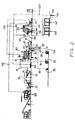
- the inventive apparatus being considered is substantially comprised of a first apparatus section represented in Figures 1 and 4-11, arranged so as to recover and appropriately treat such waste insulating materials, as this shall be described in greater detail further on, a second apparatus section represented in Figures 2 and 12-14, arranged so as to separate the liquids contained in the waste insulating materials therefrom and clean the same liquids to remove dirt and contaminants therefrom, as this shall be described in greater detail further on, and a third apparatus section represented in Figure 3, arranged so as to appropriately store the so obtained ground waste materials in view of them being subsequently recycled for re-use.
- the first section of the apparatus is substantially comprised of loading and shredding means 5, in which waste material - as previously collected separately by firms specializing in collecting and recycling waste material in general - is introduced and shredded into thin, minute strips and fibres, separator means 6 to separate metal magnetic materials that may be contained in the shredded waste material, washing means 7 to properly wash the shredded waste material and separate the contaminant liquids contained in the same waste material, so that said liquids - as duly separated - can then be conveyed into the second section of the apparatus to be cleaned for re-use, washing and drying means 8 to handle the shredded and washed waste material, i.e.
- grinding means 9 to grind and triturate the shredded, washed and dried waste material, so as to obtain particles of material having the desired size and shape
- storage means 10 to collect and temporarily hold all waste material being so treated, for it to be eventually transferred to the third section of the apparatus, in which the treated waste material is stored until it is eventually removed for re-use in the intended application.
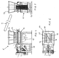
- FIG. 4 to 6 in which the loading and shredding means 5 are illustrated schematically, it can be noticed that these means are basically comprised of a metal casing 11 delimiting at least an internal shredding chamber 12 communicating with an upper loading hopper 13, into which the previously collected waste material is introduced.
- the waste material is first placed on the lower terminal zone of a continuously moving, inclined conveyor belt 14 to be thereby conveyed up to the upper terminal zone of the same conveyor belt, which is located above the hopper 13, and from which said waste material is ultimately cause to fall by gravity into the same hopper, thereby being ultimately introduced in the internal shredding chamber 12.
- This shredding chamber 12 is formed of planar, downwards inclined walls 15, within which there is housed at least a horizontal-axis revolving cylinder 16, which is rotatably driven in a continuous manner by a drive motor 17, and which is provided - along the circumference thereof - with cutting blades 18 appropriately spaced axially and at an angle relative to each other, and rotating close by, i.e.
- the above-cited separator means 6 are substantially comprised of a continuously moving conveyor belt 21, which is made of a magnetizable material and arranged to run in a parallel and transverse direction relative to the inclined conveyor belt 20, with a length that is greater than the width of said conveyor belt and slightly raised relative to the latter.
- a cylinder 22 of a permanent magnetic material which is arranged in a position lying between the upper planar section 23 and the lower planar section 24 of said magnetizable conveyor belt, close by said lower section of magnetizable conveyor belt, so as to allow a magnetic field to be only generated through said lower section of magnetizable conveyor belt, in which said magnetic field is of such an intensity and strength as to be able to attract the magnetic metal material contained in the shredded waste material being conveyed on the conveyor belt 20, thereby causing said magnetic metal material to move away and separate from said shredded waste material, wherein the so attracted magnetic metal material will then come off said lower section of conveyor belt in the zone of said magnetizable conveyor belt where the movement direction thereof is reversed, and where there is no magnetic field, to eventually fall into and be collected in appropriately provided bins (not shown).
- washing means 7 are illustrated schematically, it can be noticed that they are substantially comprised of a water-operated centrifugal machine 25 having an inclined axis of rotation and containing an internal perforated rotating drum 26 that is rotatably driven at a spinning speed of approx.
- This centrifugal or spinning machine 25 is furthermore connected to water supply conduits 30, through which wash water, as duly mixed with appropriate biocide substances capable of destroying bacterial florae existing in the waste material, is caused to continuously circulate so as to bring about an effective washing and disinfecting action on said waste materials.
- Such biocide substances are mixed with the water in the second section of the apparatus, in the manner as shall be described further on, and preferably comprise quaternary ammonium and/or glutaraldehyde, or other suitable substances that are normally used to such purposes.
- the centrifugal machine being considered is provided with an upper opening 31 communicating with the loading hopper 29, so as to enable the waste material being let into the same hopper to enter the inner chamber of the rotating drum 26; it is further provided with a pair of lower outlet openings 32 and 33 intended to let out the waste material, as duly washed, disinfected and sanitized by the above-mentioned biocide substances, and the polluted washing liquids and contaminants separating from the mass of waste materials, respectively.
- the waste material being introduced through the loading hopper 29 reaches continuously into the rotating drum 26 of the centrifugal machine, which is in turn continuously driven to rotate at a centrifugal, i.e. spinning speed, and that the mixture of water and biocide substances is at the same time let continuously into said drum, thereby wetting and soaking the mass of waste material being spun, thus causing the same waste material to be effectively washed, disinfected and sanitized.
- Rotating the drum at such spinning speed causes the waste material to be not only washed, disinfected and sanitized by the action of the in-flowing mixture of water and biocide substances, but also spin-extracted by the action of the high spinning rate, which the drum is driven to rotate at, so that the dirty and polluting liquids being extracted from the waste material are thrown centrifugally outwards and, by passing through the perforations in the peripheral wall of the drum, are conveyed into and through the lower outlet opening 33, from which they are then taken and caused to circulate through a series of conduits (not shown) connected to such opening, to be conveyed towards the component parts of the second section of the apparatus, which - as this shall be duly described and explained further on - are specially provided to clean said liquids, in view of having all solid and liquid dirt and contaminants contained in said liquids duly separated therefrom and the same liquids recovered, so that they can be recycled for re-use in the same apparatus.
- the washed, disinfected and sanitized waste material coming out through the lower outlet opening 32 is in turn transferred by gravity towards the lower terminal zone of a further inclined conveyor belt 34 arranged below said outlet opening 32, in a position coinciding therewith, the upper terminal zone of such conveyor belt ending above the loading hopper 35 of the subsequent washing and drying means 8, in a position coinciding with said hopper, so as to let such washed, disinfected and sanitized waste material into said subsequent washing and drying means.
- these further washing and drying means 8 are comprised of a further centrifugal machine 36 of the same kind as the previously described one, which in this case is however no longer connected to conduits for the supply of water and biocide substances, but is again provided with a perforated rotating drum (not indicated) that is driven at a spinning speed of approx. 1800 rpm, in the internal chamber of which the waste material is introduced through the loading hopper 35 to the purpose of using the effect of the centrifugal action to cause on the one side said waste material to be on the one side spin-extracted and dried and, on the other side, solid foreign matters contained in the same waste material to be separated therefrom.
- a further centrifugal machine 36 of the same kind as the previously described one, which in this case is however no longer connected to conduits for the supply of water and biocide substances, but is again provided with a perforated rotating drum (not indicated) that is driven at a spinning speed of approx. 1800 rpm, in the internal chamber of which the waste material is introduced through the loading hopper 35
- this machine is also provided with two lower outlet openings (not visible) to let out the almost dry waste material, upon completion of the related spin-extraction cycles performed over pre-set periods of time, and the solid foreign matters separated therefrom, respectively, wherein such dried waste material are then transferred towards the lower terminal zone of a next continuously moving, inclined conveyor belt 37 that is arranged below the related outlet opening in correspondence thereto, whereas the upper terminal zone of this conveyor is led through the subsequent grinding means 9, so as to introduce said dry waste material carried by the inclined conveyor belt 37 in said grinding means, whereas the solid foreign matters separated therefrom are in turn caused to circulate through proper conduits (not shown) and eventually discharged outside.
- this grinding chamber 40 there is provided at least a horizontal-axis rotor 43 that is continuously driven rotatably by a drive motor 44 and carrying a set of cutting blades 45, between which the waste material introduced through the hopper 41 is caused to pass, so that said waste material is ground into granular particles, the maximum allowable particle size of which being determined by an associated sieve arranged therebelow (not shown).
- the rotor 43 is in turn cooled by water circulating through a specially provided water-carrying circuit (not shown) that is incorporated in this internal grinding chamber 40, thereby keeping the waste material being ground at a constant temperature that is lower than the melting temperature of the same waste materials, so as to prevent the mass of waste material being ground from undesirably melting.
- the lower collecting chamber 42 is provided inside an unloading hopper 46, in which there is accommodated a continuously revolving rotary screw feeder 47, situated in a position below the rotor 43 and provided with suitably downward inclined walls and a side or bottom outlet opening 48 for the ground waste material falling down from the rotor 43 to be able to exit therethrough, said screw feeder being driven to rotate in a single direction, so as to enable it to convey the ground waste material falling onto it towards said outlet opening.
- a continuously revolving rotary screw feeder 47 situated in a position below the rotor 43 and provided with suitably downward inclined walls and a side or bottom outlet opening 48 for the ground waste material falling down from the rotor 43 to be able to exit therethrough, said screw feeder being driven to rotate in a single direction, so as to enable it to convey the ground waste material falling onto it towards said outlet opening.
- This outlet opening 48 is furthermore connected to an aspirator 49 connected to a portion of vertical conduit 50 that extends with a portion of horizontal conduit 51 connecting with the upper part of the storage means 10, which are provided in the form of a large-capacity vertical silo 52, to the purpose of aspirating the ground waste material collecting into the collecting chamber 42 of the mill 38 and conveying it via said conduits into the silo 52, in which said ground waste material is introduced and kept stored, ready for use when needed, in which case the same material is transferred towards the third section of the apparatus, in the manner and to the purposes as this will be described below.
- this second section of the apparatus is substantially comprised of a first component part 53 and a second component part 54, whose construction and operation shall be described in greater detail further on, and which are arranged in a sequence relative to each other so as to be able to purify - in successive steps - the soiled and polluting liquids flowing in from the centrifugal machine 36, in view of obtaining dried solid waste substances, which are directly discharged and disposed of, and liquids that are further purified in successive steps for them to be capable of being re-used in the apparatus.
- it further includes filtering means 55 and settling means 56 provided to further purify the liquids that have already undergone a first purifying stage through said first and said second component part 53 and 54, thereby separating dried solid waste substances (sand, mud, sludge and the like) from said liquids and obtaining clean liquids that are re-used by letting them again into the centrifugal machine 25, whereas the separated solid waste substances are again duly disposed of.
- filtering means 55 and settling means 56 provided to further purify the liquids that have already undergone a first purifying stage through said first and said second component part 53 and 54, thereby separating dried solid waste substances (sand, mud, sludge and the like) from said liquids and obtaining clean liquids that are re-used by letting them again into the centrifugal machine 25, whereas the separated solid waste substances are again duly disposed of.
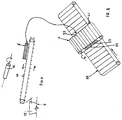
- Figure 16 more clearly illustrates the first component part 53, which is substantially comprised of an elongated collecting tank 57 extending horizontally, as well as an inclined conveyor device 58 that is led with the lower end portion thereof into said tank, as this shall be described in greater detail further on, said tank being in turn subdivided by a vertical partition wall 59 into a first tank portion 60 and a second tank portion 61 separated from the first one, these portions being provided to the purposes that shall be described further on.
- the first tank portion 60 is provided with a smaller capacity than the second tank portion 61 and communicates, via a conduit 62 and a pump 63, with the lower outlet opening 33 of the centrifugal machine, in such a manner as to enable the soiled and polluting liquids flowing from the centrifugal machine 25 to be collected, as conveyed there by the suction action of said pump, into said tank portion 60.
- the inclined conveyor device 58 is in turn comprised of an inclined hollow conduit 64 and a revolving screw feeder 65, or similar conveying means, housed within said hollow conduit and submerged with the lower end portion thereof in the soiled and polluting liquids collected in the first tank portion 60.
- said inclined hollow conduit 64 there is arranged internally an abutment wall (not shown), situated close by the revolving screw feeder 65, and there are further connected below an outlet conduit 66 and a conveying conduit 67 communicating on one side with the inner cavity of the inclined conduit 64 and, on the opposite side, with a collecting vessel 68 situated therebelow, such as for instance a bin or skip, and the second tank portion 61, respectively.
- FIG. 17 Illustrated in Figure 17 is a detailed representation of the above-mentioned second component part 54, which is substantially comprised of a loading hopper 71 in a roughly trapezoidal shape, and with an adequately large containment volume, which is closed by an upper wall 72 provided with a conduit portion 73 that connects to said conduit 70, is delimited downwards by a perforated inclined bottom 74, and is sustained on the ground by supporting legs 75.
- This second component part further includes an inclined hollow conduit 76 attached on the outside against said perforated inclined bottom all along the length thereof, and protruding beyond said bottom, in which this conduit is further perforated along the region thereof that is in contact with said bottom and accommodates in its interior a rotary screw feeder 77 - or any other equally effective forward-moving device - that is driven into continuous rotation by a gear-motor 78, and in which this conduit is provided at the upper end portion thereof with an unloading conduit 79 communicating with the internal cavity thereof.
- the soiled and polluting liquid substances contained in the second tank portion 61 are drawn in by the pump 69 and conveyed through the conduit 70 into the collecting chamber of the loading hopper 71, where the heavier solid particles in said substances (eg., sand, mud, and the like) separate from the liquid portion of the same substances and settle by gravity onto the bottom 74 of the same hopper, from which they are then able to move into the internal cavity of the inclined conduit 76 by passing through the perforations in said bottom and said conduit, whereas the liquid portion of said soiled and polluting liquid substances remains in turn contained in the collecting chamber of the hopper 71.
- the heavier solid particles in said substances eg., sand, mud, and the like
- the solid particles moving into said inclined conduit 76 are moved further on by the rotary screw feeder 77 towards the upper end portion of the same conduit, from which they are then caused to pass through the unloading conduit 79 to ultimately fall into a collecting bin provided therebelow (not shown) in view of the final disposal thereof.
- the collecting chamber of the hopper 71 is in turn provided with a further side conduit portion 80, connected to a further conduit 81 leading to the filtering arrangement 55, so as to convey the liquid portion contained in said collecting chamber towards such filtering arrangement.
- the filtering arrangement 55 is substantially comprised of a perforated horizontal-axis rotating cylinder 82 provided with a fine-mesh filtering surface and housed in a support structure 83 resting on the ground, that is closed below and open on top.
- This cylinder is driven into continuous rotation by a drive motor of its own (not shown) and delimitates an inner chamber adapted to contain the liquid portion to be further purified, and flowing in from the loading hopper 71 as this shall be described in greater detail further on, so that the solid particles that may be still present in said liquid portion are separated therefrom by the rotation of said cylinder.
- the so separated particles remain in the inner chamber of said cylinder, from which they are then unloaded outside through a first unloading conduit 84 communicating with said inner chamber, and attached in the lower portion of the support structure 83, to ultimately fall into a collecting bin 85 provided therebelow, in a separate position relative to said first unloading conduit 84, whereas the filtered liquids passing through the filtering meshes of the cylinder are let outside through a second outlet conduit 86 that is again attached in the lower portion of the support structure 83, to ultimately fall into a large-capacity collecting tank 87 provided in a position below said second outlet conduit 86.
- the inner chamber of the rotating cylinder 82 communicates, via an inlet port 88 opening in the side of the support structure 83, with a separate large-capacity tank 89 acting as a temporary storage buffer, which is situated upstream of the same rotating cylinder and connects to the conduit 81 extending from the collecting chamber of the loading hopper 71 under interposition of an intake pump (not shown) that is adapted to draw in the liquid portion contained in said collecting chamber of the hopper and convey it into said separate tank 89, from which it is then caused - at desired moments with the aid of appropriate valve means (not shown) - to fall by gravity into said inner chamber of the rotating cylinder 82.
- an intake pump not shown
- the solid waste particles collecting in the inner chamber of the rotating cylinder 82 are scraped off the filtering surface of the same cylinder by an internal screw-shaped blade (non visible) moving close by said filtering surface so as to graze it, to be then let out through the above-described first unloading conduit 84.
- an internal screw-shaped blade non visible moving close by said filtering surface so as to graze it, to be then let out through the above-described first unloading conduit 84.
- removal of said solid particles adhering against the filtering surface is also facilitated by the use of the water contained in a separate water-carrying circuit (not shown), which is suitably sprayed at intervals against the same surface.
- This filtering arrangement 55 is furthermore associated to a further inclined hollow conduit 90, which is provided downstream of the first unloading conduit 84 of the rotating cylinder 82 and accommodates a rotary screw feeder 91 therewithin, said inclined conduit sustaining at the lower end portion thereof the afore-described collecting hopper 85, into which the solid waste particles falling from said first unloading conduit 84 are introduced to then enter the inner cavity of the inclined conduit 90 and be moved further on by the slowly rotating screw feeder 91 towards the upper end portion of the same conduit, in which these solid waste particles are squeezed, compacted and extracted against an abutment wall (not shown) provided in this zone of the inclined conduit 90.
- This collecting tank 87 is in turn connected - via respective conduits 95, 96, 97 - to corresponding reservoirs 98. 99, 100, which are provided to contain biocide substances, a polyelectrolyte and aluminium polychloride, respectively.
- the biocide substances are intended to destroy bacterial florae that are present in the waste materials being processed in the apparatus.
- the polyelectrolyte is intended to cause sludge to flocculate and, as a result, to thicken
- this polyelectrolyte may be completed through the addition of one or more possible anti-frothing agents of a traditional kind, as contained in corresponding reservoirs (not shown), in the presence of whirling or turbulent flows that may give rise to foaming.
- aluminium polychloride is intended to cause sludge to precipitate.
- the settling means 56 which are substantially comprised of a large-capacity settling tank 101 for sludge and solid waste substances, and a liquid collecting tank 102 situated upstream of said settling tank 101 and communicating with the latter via a lower conduit 103 for causing the purified liquids contained in the collecting tank 102 - and introduced in said tank by means of a suction pump 104 connected to the previously described collecting tank 87 of the filtering means 55 - to overflow, i.e. skim over into said settling tank.
- the settling tank 101 contains appropriately shaped and sized lamellar conveying means 105, provided there to convey the purified liquids introduced in the same tank along appropriate internal flowpaths in view of causing the liquid portion, which remains in the upper layers of the liquid mass, or slurry, to be progressively separated from the solid waste portion, which settles and collects on the bottom of said settling tank 101, from which it is then removed and conveyed by a screw pump 106, situated under the bottom of the tank itself, towards a sequence of very finely meshed filtering bags 107, or towards duly provided filter-presses or centrifugal separators, in which said sludge and other solid waste substances still present in the solid waste portion remain inside said bags (or filter-presses or centrifugal separators) to be then suitably removed and disposed of, whereas the purified liquid - as separated from said solid waste portion - is conveyed through a lower conduit into a further collecting tank 108.
- This collecting tank 108 is in turn connected - via a conduit 109 and a pump 110 - to the centrifugal machine 36, so as to be able to convey the purified, disinfected and sanitized water again into the same centrifugal machine.
- the purified, disinfected and sanitized liquid is caused to overflow, i.e. skim over into a storage reservoir 111, in view of being subsequently conveyed - via a conduit 112 and a pump 113 - into the centrifugal machine 36, where it is re-used to wash further waste insulating materials loaded thereinto.
- the above-mentioned storage reservoir 111 is additionally supplied from a separate conduit 114 with clean fresh water flowing in from the external water supply line to thereby compensate for the unavoidable loss in purified and sanitized liquid occurring in this portion of the apparatus.
- FIG. 3 illustrates the third section of the inventive apparatus, which is specially provided to package - in bags or other suitable containers - the ground, cleaned, disinfected and sanitized waste materials stored in the silo 52
- this third section is substantially comprised of a bag carrying line 115, in which the bags being filled with said waste materials are placed, and a pallet storing and transporting line 116, provided separately from and parallel to the above-mentioned line 115, in which the bags containing the recovered waste materials are transferred and loaded onto a pallet at a time, to be subsequently loaded on trucks or transported in any other suitable manner to the place where these recovered waste materials are eventually re-used.
- the bag transport line 115 is substantially comprised of a loading hopper 117, into which the recovered, ready-for-use waste materials are introduced from the storage silo 52, as conveyed through a first and a second conduit 118 and 119, of which the first conduit 118 is intercepted by a rotary conveying screw 120, is connected with an end portion thereof to the upper portion of the same silo, and terminates with the other end portion thereof in a position lying above a vibratory belt 121 communicating with a further rotary conveying screw 122, which in turn communicates with the hopper 117 via a second conduit 119.
- the conveyance of the waste materials occurs through the rotary screws 120 and 122 and the vibratory belt 121, whereas the rotary screw 120 is in turn communicating also with a further conduit 123, the task of which is to selectively convey the waste materials and let them into further separate containers placed elsewhere in the plant, or to receive further ground, cleaned, disinfected and sanitized waste materials processed elsewhere, to the purpose of mixing them with the waste materials stored in the silo and introduce them in the loading hopper 117 serving the bag transport line 115.
- This bag transport line 115 further includes a station 124 arranged under the loading hopper 117 for supporting and forming the bag material, a conveyor belt 125 for transporting the bag material filled with waste material, moving intermittently and unidirectionally in the direction A, a station 126 for squaring up the so filled bags, a station 127 for positioning the filled bags, and a motor-driven roller conveyor 128 for transporting the filled bags, moving again intermittently and unidirectionally in the same direction A.
- the station 124 provided to support and form the bag material is comprised of a motor-driven horizontal-axis revolving roller 129, arranged to lie across the line below the loading hopper 117, and on which there is wound the bag material.
- This unwinding roller 129 is first rotatably driven so as to cause the bag material to be laid in position under the loading hopper 117, then its rotation is stopped so as to allow a pre-set amount of the waste materials being introduced through the loading hopper 117 to be let onto the so arranged bag material.
- the thus formed bag is welded along the side edges and the bottom thereof by means of a welding machine (not shown) situated close by said unwinding roller 129, and said filled bag is then deposited onto the conveyor belt 125 to be carried by the latter below a vertical piston 130, which is also situated in this support and bag formation station 124, so that the vertical displacement of this piston causes the recovered waste materials inside the bag to be compacted and evenly distributed therewithin.
- This squaring-up station 126 is essentially comprised of a suitable press (not shown) which, as soon as the filled bag reaches its due position and stops there, is operated to confer the bag its desired shape.
- the so shaped bag is then carried further forwards by the conveyor belt 125, until it eventually reaches the positioning station 127, where it is stopped so as to enable this positioning station to position the bag in the desired manner on said conveyor belt 125, eg., standing in an upright position or laid down on the conveyor, while the subsequent forward movement of said conveyor belt carries the bag to be placed on the motor-driven roller conveyor 128, which in turn carries the bag further on up to the end thereof, where there is provided a movable trigger arm 131.
- this trigger arm causes the motor-driven roller conveyor 128 to stop moving, thereby placing the bag in a position coinciding with a platform elevator 132, which is displaceable vertically and crosswise and is situated between the bag transport line 115 and the pallet storage and transport line 116.
- a platform elevator 132 which is displaceable vertically and crosswise and is situated between the bag transport line 115 and the pallet storage and transport line 116.
- the bag is moved onto said platform elevator 132, wherein the same platform is then displaced transversally until it falls into alignment with the pallet storage and transport line 116: then it is displaced vertically to bring the bag at the desired height, thereby making it ready for loading onto a pallet.
- the pallet storage and transport line 116 is in turn comprised of a number of pallets 133 stacked upon each other, wherein new pallets are continuously added to this stack as existing ones are taken therefrom to be loaded with bags; it further comprises a first and a second motor-driven roller conveyor 134 and 135 aligned with and spaced from each other by a distance enabling the platform elevator 132 to be accommodated therebetween, wherein the first roller conveyor 134 is intended to move the from time to time upper pallet towards said space provided therebetween, in such a manner as to ensure that, when a platform elevator is loaded with a row of bags at a time, the same can be raised to the same height as such pallet, so as to be able to load the related bags onto said pallet, to be then brought back - through an inverted motion sequence - into the primitive position, where it is able to receive new bags.
- the second roller conveyor 135 is on the contrary intended to carry the pallet loaded with bags towards the next unloading station 136, in which there is arranged a semi-automatic coiler 137 provided with straps and adapted to wind said straps around the bags so as to tie them tightly together.
- the so packed bags are then removed from this unloading station by fork trucks and transported directly to the place of use of the materials, or loaded in trucks for transport to remote sites of use.
- the present invention further relates to a process for recovering and washing insulating waste materials of the afore-described kinds, in view of obtaining ground insulating waste materials capable of being recycled for re-use in various applications, particularly, although not solely, in applications where they are used and perform as heat and sound insulation materials in residential buildings, eg. in floorings and similar structures of the same buildings.
- This process which is carried out with the afore-described apparatus, comprises a step in which said waste materials are shredded into thin, minute strips and fibres in a first section of the inventive apparatus; a step in which metal magnetic materials that may be contained in the shredded waste material are separated therefrom and said waste materials are then washed in a washing arrangement and dried after washing, wherein said washing is carried out with the use of water mixed up with biocide agents, thereby obtaining shredded waste materials that are washed, disinfected and sanitized, whereas the soiled and polluting liquids that are separated therefrom during this washing step are conveyed into a second section of the inventive apparatus, in which they are separated, filtered and purified in successive steps, and further mixed up with said biocide agents, as well as anti-frothing and thickening agents, so as to be recovered for re-use in further washing sequences of new shredded waste materials, whereas separated solid substances (sand, mud, and the like) are disposed of separately; a step in
Landscapes
- Engineering & Computer Science (AREA)
- Environmental & Geological Engineering (AREA)
- Health & Medical Sciences (AREA)
- Chemical & Material Sciences (AREA)
- Chemical Kinetics & Catalysis (AREA)
- General Chemical & Material Sciences (AREA)
- General Health & Medical Sciences (AREA)
- Toxicology (AREA)
- Mechanical Engineering (AREA)
- Processing Of Solid Wastes (AREA)
Priority Applications (1)
| Application Number | Priority Date | Filing Date | Title |
|---|---|---|---|
| EP20050020194 EP1764166A1 (fr) | 2005-09-16 | 2005-09-16 | Dispositif et procédé de récupération et de lavage de déchets divers pour obtenir des matériaux isolants broyés |
Applications Claiming Priority (1)
| Application Number | Priority Date | Filing Date | Title |
|---|---|---|---|
| EP20050020194 EP1764166A1 (fr) | 2005-09-16 | 2005-09-16 | Dispositif et procédé de récupération et de lavage de déchets divers pour obtenir des matériaux isolants broyés |
Publications (1)
| Publication Number | Publication Date |
|---|---|
| EP1764166A1 true EP1764166A1 (fr) | 2007-03-21 |
Family
ID=35787988
Family Applications (1)
| Application Number | Title | Priority Date | Filing Date |
|---|---|---|---|
| EP20050020194 Withdrawn EP1764166A1 (fr) | 2005-09-16 | 2005-09-16 | Dispositif et procédé de récupération et de lavage de déchets divers pour obtenir des matériaux isolants broyés |
Country Status (1)
| Country | Link |
|---|---|
| EP (1) | EP1764166A1 (fr) |
Cited By (10)
| Publication number | Priority date | Publication date | Assignee | Title |
|---|---|---|---|---|
| CN109465280A (zh) * | 2018-12-21 | 2019-03-15 | 中山斯瑞德环保科技有限公司 | 一种纸厂绞绳制备rdf-5的设备及制备方法 |
| CN111844535A (zh) * | 2020-07-20 | 2020-10-30 | 郭芸 | 一种塑料油漆桶回收装置 |
| CN112026065A (zh) * | 2020-08-19 | 2020-12-04 | 泗县东方塑料有限责任公司 | 一种废旧塑料制品的回收再利用处理方法 |
| CN113494253A (zh) * | 2021-07-28 | 2021-10-12 | 中铁二十二局集团第一工程有限公司 | 一种高效泥浆处理设备 |
| CN114161608A (zh) * | 2021-12-07 | 2022-03-11 | 沈国建 | 一种塑料集装袋的回收造粒装置 |
| WO2022077629A1 (fr) * | 2020-10-16 | 2022-04-21 | 苏州超硕凡塑料制品有限公司 | Dispositif de traitement de recyclage de plastique pour distribution express |
| CN116637714A (zh) * | 2023-05-30 | 2023-08-25 | 铜陵国传电子材料科技有限公司 | 一种金属粉末连续分离装置及分离方法 |
| CN118079517A (zh) * | 2024-04-18 | 2024-05-28 | 广东德森环保科技有限公司 | 一种用于养殖废水的高效处理设备及处理方法 |
| CN118373473A (zh) * | 2024-06-24 | 2024-07-23 | 甘肃天辰环境工程有限公司 | 一种间歇式固废排放的污水处理机构 |
| CN119427598A (zh) * | 2024-10-30 | 2025-02-14 | 嘉善康达斯电子股份有限公司 | 一种循环型塑料废料回收处理设备 |
Citations (6)
| Publication number | Priority date | Publication date | Assignee | Title |
|---|---|---|---|---|
| DE2227004A1 (de) * | 1972-06-02 | 1973-12-13 | Texaco Development Corp | Verfahren zur beseitigung von muell und festem abfall, abwasser oder mischungen derselben |
| FR2539055A1 (fr) * | 1983-01-10 | 1984-07-13 | Carbonell Serra Enrique | Procede pour le traitement des residus urbains et installation pour sa mise en oeuvre |
| WO1995007810A1 (fr) * | 1993-09-15 | 1995-03-23 | Quadra Holding S.A. | Procede et installation de triage de matieres plastiques issues de dechets menagers et industriels |
| DE19534875C1 (de) * | 1995-09-20 | 1996-10-31 | Manfred Dr Baumgaertner | Verfahren zur Herstellung eines Isolier- und Strukturmaterials |
| WO1998003715A1 (fr) * | 1996-07-19 | 1998-01-29 | Water Recovery Systems, Inc. | Procede et dispositif de traitement des eaux de lessive usees |
| WO2005051547A1 (fr) * | 2003-11-22 | 2005-06-09 | Ecoenergy Gesellschaft Für Energie- Und Umwelttechnik Mbh | Procede et dispositif de traitement par voie humide et mecanique d'un melange de substances, en particulier de dechets de tous types |
-
2005
- 2005-09-16 EP EP20050020194 patent/EP1764166A1/fr not_active Withdrawn
Patent Citations (6)
| Publication number | Priority date | Publication date | Assignee | Title |
|---|---|---|---|---|
| DE2227004A1 (de) * | 1972-06-02 | 1973-12-13 | Texaco Development Corp | Verfahren zur beseitigung von muell und festem abfall, abwasser oder mischungen derselben |
| FR2539055A1 (fr) * | 1983-01-10 | 1984-07-13 | Carbonell Serra Enrique | Procede pour le traitement des residus urbains et installation pour sa mise en oeuvre |
| WO1995007810A1 (fr) * | 1993-09-15 | 1995-03-23 | Quadra Holding S.A. | Procede et installation de triage de matieres plastiques issues de dechets menagers et industriels |
| DE19534875C1 (de) * | 1995-09-20 | 1996-10-31 | Manfred Dr Baumgaertner | Verfahren zur Herstellung eines Isolier- und Strukturmaterials |
| WO1998003715A1 (fr) * | 1996-07-19 | 1998-01-29 | Water Recovery Systems, Inc. | Procede et dispositif de traitement des eaux de lessive usees |
| WO2005051547A1 (fr) * | 2003-11-22 | 2005-06-09 | Ecoenergy Gesellschaft Für Energie- Und Umwelttechnik Mbh | Procede et dispositif de traitement par voie humide et mecanique d'un melange de substances, en particulier de dechets de tous types |
Cited By (11)
| Publication number | Priority date | Publication date | Assignee | Title |
|---|---|---|---|---|
| CN109465280A (zh) * | 2018-12-21 | 2019-03-15 | 中山斯瑞德环保科技有限公司 | 一种纸厂绞绳制备rdf-5的设备及制备方法 |
| CN111844535A (zh) * | 2020-07-20 | 2020-10-30 | 郭芸 | 一种塑料油漆桶回收装置 |
| CN112026065A (zh) * | 2020-08-19 | 2020-12-04 | 泗县东方塑料有限责任公司 | 一种废旧塑料制品的回收再利用处理方法 |
| WO2022077629A1 (fr) * | 2020-10-16 | 2022-04-21 | 苏州超硕凡塑料制品有限公司 | Dispositif de traitement de recyclage de plastique pour distribution express |
| CN113494253A (zh) * | 2021-07-28 | 2021-10-12 | 中铁二十二局集团第一工程有限公司 | 一种高效泥浆处理设备 |
| CN114161608A (zh) * | 2021-12-07 | 2022-03-11 | 沈国建 | 一种塑料集装袋的回收造粒装置 |
| CN114161608B (zh) * | 2021-12-07 | 2024-04-12 | 广东顺德卓野塑料制品有限公司 | 一种塑料集装袋的回收造粒装置 |
| CN116637714A (zh) * | 2023-05-30 | 2023-08-25 | 铜陵国传电子材料科技有限公司 | 一种金属粉末连续分离装置及分离方法 |
| CN118079517A (zh) * | 2024-04-18 | 2024-05-28 | 广东德森环保科技有限公司 | 一种用于养殖废水的高效处理设备及处理方法 |
| CN118373473A (zh) * | 2024-06-24 | 2024-07-23 | 甘肃天辰环境工程有限公司 | 一种间歇式固废排放的污水处理机构 |
| CN119427598A (zh) * | 2024-10-30 | 2025-02-14 | 嘉善康达斯电子股份有限公司 | 一种循环型塑料废料回收处理设备 |
Similar Documents
| Publication | Publication Date | Title |
|---|---|---|
| RU2413048C2 (ru) | Агрегат для уборки дорог | |
| JPH08509782A (ja) | 廃棄物の再生処理方法およびそのための装置 | |
| JP4003923B2 (ja) | 廃プラスチックの分別処理装置とその分別処理方法 | |
| KR101561042B1 (ko) | 폐비닐 세정을 위한 트롬멜 세정기 및 이를 이용한 폐비닐 세정방법 | |
| US11389992B1 (en) | Small footprint pre-treatment plant and decentralized food waste separation and treatment | |
| WO2013012710A1 (fr) | Système de récupération de remplissage de gazon mobile | |
| CN109703957B (zh) | 一种生活垃圾的移动分类工厂 | |
| WO2019010831A1 (fr) | Véhicule enfermé intelligent pour la classification d'ordures ménagères | |
| KR20060114885A (ko) | 폐비닐의 재활용처리 방법 및 그 장치 | |
| US3817459A (en) | Device and process for reclaiming used wood | |
| CN109332353A (zh) | 一种能够自动称重计量的垃圾回收分选打包系统及其工作流程 | |
| US3653871A (en) | Method of disposing and reclaiming solid refuse | |
| CN109226189A (zh) | 一种能够自动装车的垃圾回收分选打包系统及其工作流程 | |
| CN117181768A (zh) | 一种垃圾智能分类分选装置 | |
| CN114852552A (zh) | 一种智能型的自动投放智能垃圾箱 | |
| CN213162430U (zh) | 一种建筑垃圾破碎压缩打包装置 | |
| JP2014233705A (ja) | 乾式集塵装置及び乾式集塵システム | |
| JP5130319B2 (ja) | 積載式・移動式リサイクルプラント | |
| US20020023860A1 (en) | Method and system for garbage recycling | |
| CN109226191A (zh) | 一种垃圾回收分选打包系统及其工作流程 | |
| CA3171839A1 (fr) | Systeme de triage comprenant un systeme de vaporisation et de dilution pour accroitre la proprete des plastiques et des rejets | |
| CN109226193A (zh) | 一种具备成品自动存储功能的垃圾回收分选打包系统及其工作流程 | |
| JP2000084425A (ja) | 破砕機,及び該破砕機を備えた収集装置 | |
| CN109226190A (zh) | 一种能够自动润滑的垃圾回收分选打包系统及其工作流程 | |
| US9096475B2 (en) | Garbage to fertilizer conversion system |
Legal Events
| Date | Code | Title | Description |
|---|---|---|---|
| PUAI | Public reference made under article 153(3) epc to a published international application that has entered the european phase |
Free format text: ORIGINAL CODE: 0009012 |
|
| AK | Designated contracting states |
Kind code of ref document: A1 Designated state(s): AT BE BG CH CY CZ DE DK EE ES FI FR GB GR HU IE IS IT LI LT LU LV MC NL PL PT RO SE SI SK TR |
|
| AX | Request for extension of the european patent |
Extension state: AL BA HR MK YU |
|
| 17P | Request for examination filed |
Effective date: 20070508 |
|
| 17Q | First examination report despatched |
Effective date: 20070606 |
|
| AKX | Designation fees paid |
Designated state(s): AT BE BG CH CY CZ DE DK EE ES FI FR GB GR HU IE IS IT LI LT LU LV MC NL PL PT RO SE SI SK TR |
|
| STAA | Information on the status of an ep patent application or granted ep patent |
Free format text: STATUS: THE APPLICATION IS DEEMED TO BE WITHDRAWN |
|
| 18D | Application deemed to be withdrawn |
Effective date: 20150401 |