EP1764191A2 - Marteau de couvreur multifonctions - Google Patents
Marteau de couvreur multifonctions Download PDFInfo
- Publication number
- EP1764191A2 EP1764191A2 EP06291432A EP06291432A EP1764191A2 EP 1764191 A2 EP1764191 A2 EP 1764191A2 EP 06291432 A EP06291432 A EP 06291432A EP 06291432 A EP06291432 A EP 06291432A EP 1764191 A2 EP1764191 A2 EP 1764191A2
- Authority
- EP
- European Patent Office
- Prior art keywords
- hammer
- head
- rod
- gripping
- cutting edge
- Prior art date
- Legal status (The legal status is an assumption and is not a legal conclusion. Google has not performed a legal analysis and makes no representation as to the accuracy of the status listed.)
- Granted
Links
Images
Classifications
-
- E—FIXED CONSTRUCTIONS
- E04—BUILDING
- E04D—ROOF COVERINGS; SKY-LIGHTS; GUTTERS; ROOF-WORKING TOOLS
- E04D15/00—Apparatus or tools for roof working
- E04D15/02—Apparatus or tools for roof working for roof coverings comprising tiles, shingles, or like roofing elements
-
- B—PERFORMING OPERATIONS; TRANSPORTING
- B25—HAND TOOLS; PORTABLE POWER-DRIVEN TOOLS; MANIPULATORS
- B25F—COMBINATION OR MULTI-PURPOSE TOOLS NOT OTHERWISE PROVIDED FOR; DETAILS OR COMPONENTS OF PORTABLE POWER-DRIVEN TOOLS NOT PARTICULARLY RELATED TO THE OPERATIONS PERFORMED AND NOT OTHERWISE PROVIDED FOR
- B25F1/00—Combination or multi-purpose hand tools
-
- B—PERFORMING OPERATIONS; TRANSPORTING
- B25—HAND TOOLS; PORTABLE POWER-DRIVEN TOOLS; MANIPULATORS
- B25G—HANDLES FOR HAND IMPLEMENTS
- B25G1/00—Handle constructions
- B25G1/10—Handle constructions characterised by material or shape
- B25G1/102—Handle constructions characterised by material or shape the shape being specially adapted to facilitate handling or improve grip
Definitions
- the present invention relates to a multifunctional roofing hammer of the type comprising, at the level of the hammer head, at least one striking failure, a piercing tip of the covering elements and possibly a nail puller, said head being extended by one flat shank having, on at least one of its longitudinal edges, a cutting edge for slicing the covering elements, this flat shank being provided, in the vicinity of its free end, with a manual gripping handle.
- roofing hammers are well known to those skilled in this art. They have the particularity of allowing, by means of the same tool, the exercise of several functions, namely in particular, a cutting function of the covering elements, such as slates, by means of the cutting edge forming a blade. cutter positioned in extension of the hammer head, a drilling function of the cover elements exerted using the tip of the hammer head to allow the passage of nails in said cover elements and a percussion function exerted on the hammer head; help the hammer head strike failure to allow the nails to sink.
- a cutting function of the covering elements such as slates
- cutter positioned in extension of the hammer head, a drilling function of the cover elements exerted using the tip of the hammer head to allow the passage of nails in said cover elements and a percussion function exerted on the hammer head; help the hammer head strike failure to allow the nails to sink.
- the position of the user's hand on the handle varies.
- the hand of the user is positioned in a so-called low position of the handle, in the vicinity of the free end of the handle.
- the hand of the user approaches the head of the hammer and is positioned higher on the handle.
- the handle of such a hammer is equipped with a manual gripping handle of the hammer formed by a coating surface which extends over a short length of the handle so that when the operator grasps the tool to exercise the drilling functions, his fingers close on the part of the sleeve not provided with grip grip by coming to apply on the metal part surrounding the cutting edge. This position is uncomfortable and is likely to cause a risk of injury to the operator's fingers.
- An object of the present invention is therefore to provide a roofing hammer whose design allows to have a plurality of comfortable gripping positions, each position corresponding to a function of the hammer.
- Another object of the present invention is to provide a roofing hammer whose design allows to increase or maintain a large cutting edge length while increasing the comfort of the user.
- the subject of the invention is a multifunctional roofing hammer of the type comprising, at the level of the hammer head, at least one striking failure, a perforation tip of the covering elements and possibly a nail puller, head being extended by a flat shank having, on at least one of its longitudinal edges, a cutting edge for slicing the covering elements, this flat shank being provided at or near its free end, a manual gripping handle, characterized in that the manual gripping handle has a cylindrical section throat, forming axis of rotation of the hammer during the passage from one function to another and two gripping zones arranged one, d ' one side of the throttle, between hammerhead and throttle, the other on the other side of the throttle.
- a specialized gripping zone allows the operator to have a plurality of comfortable positions without having to position part of his fingers on the metal part of the rod surrounding the cutting edge.
- the manual gripping handle is formed by coating the rod and / or an extension of the rod, in particular by overmolding.
- the manual gripping handle in the grip zone between the hammer head and the throttle, in the vicinity of the base of the cutting edge of the rod, is formed by a coating of the rod which partially surrounds said rod to leave free said cutting edge.
- This arrangement makes it possible to have several comfortable gripping positions without having to reduce the length of the cutting edge with respect to the existing hammers.
- the ratio of the length of the cutting edge on the surface of the operator's hand positioned on the handle is optimized.
- at least 95% of the hand is positioned on the handle making the gripping position comfortable.
- the roofing hammer 1 which is the subject of the invention, generally comprises a hammer head extending from a flat rod 5, this flat rod being itself provided with, at or in the vicinity its free end, a manual grip handle.
- the manual gripping handle is formed by coating the rod 5 and / or an extension of the rod 5, in particular by overmolding.
- This coating can be made of two materials of different hardness, one preferably based on polypropylene. This coating may cover a portion of the rod 5 and extend beyond said rod by coating an extension of the rod when the latter is present.
- this coating surface constituting the gripping handle is shaped to have a throat 7 and two gripping zones 8, 9 as will be mentioned below.
- the head 15 of such a roofing hammer 1 is conventionally equipped, at one of its ends, with a striking failure 2 which allows the operator to perform the percussion functions allowing the depressing nails.
- a tip 3 for perforating the cover elements for the introduction of said nails through said cover elements.
- a nail puller 4 in a substantially median zone between tip and 2 strike failure.
- This head is extended by a flat rod.
- This rod 5 comprises, on at least one of its longitudinal edges, a cutting edge 6 generally formed by a bevel of the longitudinal edge. This cutting edge 6, forming a cutting blade, is used for slicing the covering elements.
- the manual grip is positioned at or near the free end of the flat shaft.
- the manual gripping handle is formed by coating the shank 5
- the shank 5 preferably projects from said liner to form the free end of the hammer handle.
- the rod being generally metal, it results in an increase in the mechanical strength of the hammer which, when released by the roofer, tends to hit the ground by this free end of the handle.
- the fact that the stem makes protrusion of the coating increases the mechanical strength of this area of the rod exposed to shocks and therefore increase the mechanical strength of the assembly.
- the manual gripping handle generally formed by a coating of the rod 5, has a constriction 7 of cylindrical section forming axis of rotation of the hammer.
- the roofer in order to pass from the use of the striking tip 2 to the punching tip 3 or vice versa, is caused to rotate the hammer around the longitudinal axis of the latter formed by the rod 5.
- the presence of the constriction 7 of cylindrical section allows the operator to position his hand at this constriction, the circular section facilitating the pivoting of the assembly.
- This constriction 7 of cylindrical section preferably has a smooth outer surface. On either side of this constriction, there is provided each time a gripping area.
- the gripping zone closest to the hammer head is located between the hammer head and the throat 7. This zone is called the upper gripping zone and is represented at 9 in the figures. It is used more particularly during drilling operations of a roofing element. Indeed, in this case, it is preferable that the hand 14 of the operator, as shown in Figure 4, is positioned as close as possible to the head 15 of the tool. This hand remains however 95% on the handle and not on a metal part as in the state of the art without the useful length of the cutting edge 6 has been decreased as will be described below.
- the other gripping zone of the tool is positioned furthest away from the hammer head, that is to say the one closest to the free end of the hammer handle, between the free or proximal end of the hammer and the throat 7.
- This zone 8 is used more particularly during slicing operations of the covering element.
- the operator positions the palm of his hand in the zone 8, his index coming to bear in the zone 9. The index tends to apply the hammer against the anvil. When hammer strike failure 2 is used, this position is also preferred.
- the manual gripping handle can be formed at least partially by coating the rod 5.
- This interruption of the coating at the edge 6 over at least a portion of the length of the gripping zone 9 affects the shape of a notch.
- This interruption of the coating, at the cutting edge 6, can also extend over the entire length of the gripping zone 9.
- This arrangement makes it possible to obtain a cutting edge length of relatively large length without the portion of the cutting edge, positioned in the vicinity of the gripping zone 9 of the tool, hindering the operator.
- the presence of grip grip coating between the throat 7 and the hammer head greatly increases user comfort without adversely affecting the effective length of the cutting edge of the shank.
- the gripping handle preferably comprises zones of different hardness. These areas of different hardness can be obtained using a bi-material coating. The areas of least resistance are intended to absorb the vibrations generated by certain operations of the hammer. In addition, some areas can be treated anti-skid. For this purpose, it can be provided on the surface of said zones, a graining to increase the coefficient of friction of said surface.
- the gripping zone 8 furthest from the head has an ovoid shape. This lower part of the oval section handle facilitates the gripping by the operator of said tool.
- This gripping zone 8 farthest from the head also has, in the extension of the longitudinal edges of the rod 5, weaker zones. resistor constituting surfaces 12 of support of the palm of the hand.
- these areas 12 of lower resistance are axially offset along the handle of the tool. These zones 12 extend facing a slice of the rod 5, it being understood that the rod 5 is a flat rod which has two faces connected to each other at their longitudinal edges by surfaces constituting the slices of the rod. one of the slices having a cutting edge 6 of the rod 5.
- the gripping zone 9 of the gripping handle closest to the hammer head 15 has, for its part, two flats 10 facing the faces of the rod 5, these flats 10 forming a bearing surface for one of the fingers of the user.
- one of the flats is a bearing surface of the index of the user during the cutting or slicing position of a cover element.
- the other flat is more particularly used for left-handed people.
- Each flat portion 10 is in the form of a plane inclined toward the head of the hammer 1.
- connection zone between the two flats 10 is in turn a bearing surface 11 of the thumb of the operator.
- the surface 11 of support of the thumb is thus located opposite the edge of the rod 5 devoid of the cutting edge 6.
- the flats are generally treated as a surface of least resistance.
- the hand of the operator is, at any time, positioned on the gripping handle which constitutes a pleasant and comfortable surface and not directly on the flat rod as it could be in the case state of the art.
- the tip 2 and the nail driver 4 are made in one piece.
- This configuration makes it possible to increase the mechanical strength of the hammer head and to guarantee optimum positioning of the nail puller 4 with respect to the hammer flat shank 5 limiting the risk of breakage of the nail puller. during a pull on the latter.
- the hammer head and the rod can be made in one piece.
Landscapes
- Engineering & Computer Science (AREA)
- Mechanical Engineering (AREA)
- Architecture (AREA)
- Civil Engineering (AREA)
- Structural Engineering (AREA)
- Percussive Tools And Related Accessories (AREA)
Abstract
Description
- La présente invention concerne un marteau de couvreur multifonctions du genre comprenant, au niveau de la tête du marteau, au moins une panne de frappe, une pointe de perforation des éléments de couverture et éventuellement un tire-clou, ladite tête étant prolongée d'une tige plate possédant, sur au moins l'un de ses bords longitudinaux, une arête de coupe servant au tranchage des éléments de couverture, cette tige plate étant munie, au voisinage de son extrémité libre, d'une poignée de saisie manuelle.
- Les marteaux pour couvreur sont bien connus à ceux versés dans cet art. Ils présentent la particularité de permettre, au moyen d'un même outil, l'exercice de plusieurs fonctions, à savoir notamment, une fonction de coupe des éléments de couverture, tels que des ardoises, au moyen de l'arête tranchante formant lame de coupe positionnée en prolongement de la tête du marteau, une fonction de perçage des éléments de couverture exercée à l'aide de la pointe de la tête de marteau pour permettre le passage des clous dans lesdits éléments de couverture et une fonction de percussion exercée à l'aide de la panne de frappe de la tête du marteau pour permettre l'enfoncement des clous.
- Selon la fonction à remplir, la position de la main de l'utilisateur sur le manche varie. Ainsi, lors de l'exercice des fonctions de coupe et de percussion, la main de l'utilisateur est positionnée dans une position dite basse du manche, au voisinage de l'extrémité libre du manche. A l'inverse, lors de l'exercice de la fonction de perçage, la main de l'utilisateur se rapproche de la tête du marteau et est positionnée plus haut sur le manche.
- Dans l'état de la technique, tel qu'illustré par le brevet
US-6.460.21 0 , le manche d'un tel marteau est équipé d'une poignée de saisie manuelle du marteau formée par une surface de revêtement qui s'étend sur une faible longueur du manche de telle sorte que lorsque l'opérateur saisit l'outil pour exercer les fonctions de perçage, ses doigts se referment sur la partie de manche non pourvue de poignée de saisie en venant s'appliquer sur la partie métallique entourant l'arête de coupe. Cette position est inconfortable et est susceptible d'engendrer un risque de blessure des doigts de l'opérateur. - Il est également connu des marteaux exempts d'arête de coupe dont le manche comporte deux positions de saisie comme l'illustrent en particulier le brevet
DE-20122039 . - Un but de la présente invention est donc de proposer un marteau de couvreur dont la conception permet de disposer d'une pluralité de positions de saisie confortables, chaque position correspondant à une fonction du marteau.
- Un autre but de la présente invention est de proposer un marteau de couvreur dont la conception permet d'accroître ou de maintenir une longueur d'arête de coupe importante tout en augmentant le confort de l'utilisateur.
- A cet effet, l'invention a pour objet un marteau de couvreur multifonctions du genre comprenant, au niveau de la tête du marteau, au moins une panne de frappe, une pointe de perforation des éléments de couverture et éventuellement un tire-clou, ladite tête étant prolongée d'une tige plate possédant, sur au moins l'un de ses bords longitudinaux, une arête de coupe servant au tranchage des éléments de couverture, cette tige plate étant munie, à ou au voisinage de son extrémité libre, d'une poignée de saisie manuelle, caractérisé en ce que la poignée de saisie manuelle présente un étranglement de section cylindrique, formant axe de rotation du marteau lors du passage d'une fonction à une autre et deux zones de préhension disposées l'une, d'un côté de l'étranglement, entre tête de marteau et étranglement, l'autre de l'autre côté dudit étranglement.
- Le fait d'avoir prévu sur la poignée, de part et d'autre de l'étranglement formant axe de rotation du marteau, une zone de préhension spécialisée permet à l'opérateur de disposer d'une pluralité de positions confortables sans avoir à positionner une partie de ses doigts sur la partie métallique de la tige entourant l'arête de coupe.
- Selon une forme de réalisation préférée de l'invention, la poignée de saisie manuelle est formée par revêtement de la tige et/ou d'un prolongement de la tige, notamment par surmoulage.
- Dans un mode de réalisation particulier de l'invention, la poignée de saisie manuelle, dans la zone de préhension entre tête de marteau et étranglement, au voisinage de la base de l'arête tranchante de la tige, est formée par un revêtement de la tige qui entoure partiellement ladite tige pour laisser libre ladite arête de coupe.
- Cette disposition permet de disposer de plusieurs positions de saisie confortables sans avoir à réduire la longueur de l'arête de coupe par rapport aux marteaux existants. Le ratio longueur de l'arête de coupe sur surface de la main de l'opérateur positionnée sur la poignée est optimisé. Ainsi, par rapport à l'état de la technique, dans toutes les positions, au moins 95 % de la main est positionnée sur le manche rendant la position de saisie confortable.
- L'invention sera bien comprise à la lecture de la description suivante d'exemples de réalisation, en référence aux dessins annexés dans lesquels :
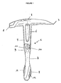
- la figure 1 représente une vue de face d'un marteau de couvreur conforme à l'invention ;
- la figure 2 représente une vue partielle de côté de la figure 1 ;
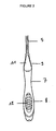
- la figure 3 représente une vue schématique d'un marteau et de la main d'un opérateur en position de tranchage d'un élément de couverture et
- la figure 4 représente une vue schématique d'un marteau et de la main d'un opérateur en position de perçage d'un élément de couverture.
- Comme mentionné ci-dessus, le marteau 1 de couvreur, objet de l'invention, comporte de manière générale une tête 15 de marteau se prolongeant d'une tige 5 plate, cette tige 5 plate étant elle-même munie, à ou au voisinage de son extrémité libre, d'une poignée de saisie manuelle. Dans les exemples représentés, la poignée de saisie manuelle est formée par revêtement de la tige 5 et/ou d'un prolongement de la tige 5, notamment par surmoulage. Ce revêtement peut être réalisé en deux matières de dureté différente, l'une de préférence à base de polypropylène. Ce revêtement peut couvrir une partie de la tige 5 et s'étendre au-delà de ladite tige en revêtant un prolongement de la tige lorsque ce dernier est présent. Dans tous les cas, cette surface de revêtement constitutive de la poignée de préhension est conformée pour présenter un étranglement 7 et deux zones 8, 9 de préhension comme cela sera mentionné ci-après.
- La tête 15 d'un tel marteau 1 de couvreur est, de manière classique, équipée, à l'une de ses extrémités, d'une panne 2 de frappe qui permet à l'opérateur d'exercer les fonctions de percussion autorisant l'enfoncement des clous. A l'extrémité opposée de ladite tête, il est prévu une pointe 3 permettant la perforation des éléments de couverture pour l'introduction desdits clous à travers lesdits éléments de couverture. Il peut également être prévu un tire-clou 4 dans une zone sensiblement médiane entre pointe et panne 2 de frappe. Cette tête est prolongée d'une tige 5 plate. Cette tige 5 comporte, sur au moins l'un de ses bords longitudinaux, une arête 6 de coupe formée généralement par un biseau du bord longitudinal. Cette arête 6 de coupe, formant lame de coupe, sert au tranchage des éléments de couverture.
- La poignée de saisie manuelle est quant à elle positionnée à ou au voisinage de l'extrémité libre de la tige 5 plate. Lorsque la poignée de saisie manuelle est formée par revêtement de la tige 5, la tige 5 fait, de préférence, saillie dudit revêtement pour former l'extrémité libre du manche du marteau. Ainsi, la tige étant généralement en métal, il en résulte une augmentation de la résistance mécanique du marteau qui, lorsqu'il est lâché par le couvreur, à tendance à heurter le sol par cette extrémité libre du manche. Le fait que la tige fasse saillie du revêtement permet d'accroître la résistance mécanique de cette zone de la tige exposée aux chocs et par suite, d'augmenter la résistance mécanique de l'ensemble.
- Comme mentionné ci-dessus, la poignée de saisie manuelle, formée généralement par un revêtement de la tige 5, présente un étranglement 7 de section cylindrique formant axe de rotation du marteau. En effet, le couvreur, pour passer de l'utilisation de la panne 2 de frappe à la pointe 3 de perforation ou inversement, est amené à entraîner en rotation le marteau autour de l'axe longitudinal de ce dernier formé par la tige 5. La présence de l'étranglement 7 de section cylindrique permet à l'opérateur de positionner sa main au niveau de cet étranglement, la section circulaire facilitant le pivotement de l'ensemble. Cet étranglement 7 de section cylindrique présente de préférence une surface externe lisse. De part et d'autre de cet étranglement, il est prévu à chaque fois une zone de préhension.
- La zone de préhension la plus proche de la tête du marteau est située entre la tête du marteau et l'étranglement 7. Cette zone est dite zone de préhension supérieure et est représentée en 9 aux figures. Elle sert plus particulièrement lors des opérations de perçage d'un élément de couverture. En effet, dans ce cas, il est préférable que la main 14 de l'opérateur, telle qu'illustrée à la figure 4, soit positionnée le plus proche possible de la tête 15 de l'outil. Cette main demeure toutefois à 95 % sur la poignée et non sur une partie métallique comme dans l'état de la technique sans que la longueur utile de l'arête 6 de coupe n'ait été diminuée comme cela sera décrit ci-après.
- L'autre zone de préhension de l'outil, représentée en 8 aux figures, est positionnée la plus éloignée de la tête 15 du marteau, c'est-à-dire le plus proche de l'extrémité libre du manche du marteau, entre l'extrémité libre ou proximale du marteau et l'étranglement 7. Cette zone 8 sert quant à elle plus particulièrement lors des opérations de tranchage de l'élément de couverture. Dans ce cas, l'opérateur positionne la paume de sa main dans la zone 8, son index venant prendre appui dans la zone 9. L'index tend à appliquer le marteau contre l'enclume. Lorsque la panne 2 de frappe du marteau est utilisée, cette position est également préférée.
- Comme mentionné ci-dessus, la poignée de saisie manuelle peut être formée au moins partiellement par revêtement de la tige 5. Dans ce cas, le revêtement constitutif de la poignée, dans la zone 9 de préhension, située la plus proche de la tête de marteau, au voisinage de la base de l'arête 6 tranchante de la tige 5, entoure partiellement ladite tige 5 sur au moins une partie de la longueur de la zone 9 pour laisser libre ladite arête 6 de coupe. Cette interruption du revêtement au niveau de l'arête 6 sur au moins une partie de la longueur de la zone 9 de préhension affecte la forme d'un encochage. Cette interruption du revêtement, au niveau de l'arête 6 de coupe, peut également s'étendre sur toute la longueur de la zone 9 de préhension. Cette disposition permet d'obtenir une longueur d'arête de coupe de longueur relativement importante sans que la portion de l'arête de coupe, positionnée au voisinage de la zone 9 de préhension de l'outil, ne gêne l'opérateur. La présence de revêtement formant poignée de saisie entre l'étranglement 7 et la tête du marteau accroît considérablement le confort de l'utilisateur sans nuire à la longueur utile de l'arête de coupe de la tige.
- Pour obtenir des zones de préhension ergonomiques, la poignée de saisie comporte, de préférence, des zones de dureté différente. Ces zones de dureté différente peuvent être obtenues à l'aide d'un revêtement bi-matière. Les zones de moindre résistance sont destinées à absorber les vibrations engendrées par certaines opérations du marteau. En outre, certaines zones peuvent être traitées antidérapantes. A cet effet, il peut être prévu, à la surface desdites zones, un grainage pour accroître le coefficient de frottement de ladite surface.
- Dans les exemples représentés, la zone 8 de préhension la plus éloignée de la tête présente une forme ovoïde. Cette partie inférieure du manche à section ovalisée facilite la préhension par l'opérateur dudit outil. Cette zone 8 de préhension la plus éloignée de la tête présente également, dans le prolongement des bords longitudinaux de la tige 5, des zones de plus faible résistance constituant des surfaces 12 d'appui de la paume de la main.
- Dans les exemples représentés, ces zones 12 de plus faible résistance sont décalées axialement le long du manche de l'outil. Ces zones 12 s'étendent en regard d'une tranche de la tige 5 étant entendu que la tige 5 est une tige plate qui présente deux faces reliées entre elles au niveau de leurs bords longitudinaux par des surfaces constituant les tranches de la tige, l'une des tranches présentant une arête 6 de coupe de la tige 5. La zone 9 de préhension de la poignée de saisie la plus proche de la tête 15 de marteau présente, quant à elle, deux méplats 10 en regard des faces de la tige 5, ces méplats 10 formant une surface d'appui pour l'un des doigts de l'utilisateur. Généralement, l'un des méplats constitue une surface d'appui de l'index de l'utilisateur lors de la position de découpe ou de tranchage d'un élément de couverture. L'autre méplat est plus particulièrement utilisé pour les gauchers. Chaque méplat 10 se présente sous la forme d'un plan incliné en direction de la tête du marteau 1.
- La zone de liaison entre les deux méplats 10 constitue quant à elle une surface 11 d'appui du pouce de l'opérateur. La surface 11 d'appui du pouce se trouve donc ainsi ménagée en regard de la tranche de la tige 5 dépourvue de l'arête 6 de coupe. Les méplats 10 sont généralement traités sous forme de surface de moindre résistance.
- Grâce à cette nouvelle conception du marteau, la main de l'opérateur est, à tout moment, positionnée sur la poignée de saisie qui constitue une surface agréable et confortable et non pas directement sur la tige 5 plate comme cela pouvait être le cas dans l'état de la technique.
- Dans un mode de réalisation préféré de l'invention, lorsque la tête du marteau est équipée d'un tire-clou 4, la panne 2 et le tire-clou 4 sont réalisés monoblocs. Cette configuration permet d'accroître la résistance mécanique de la tête du marteau et de garantir un positionnement optimal du tire-clou 4 par rapport à la tige 5 plate du marteau limitant les risques de casse du tire-clou lors d'une traction exercée sur ce dernier. De même, la tête du marteau et la tige peuvent être réalisés monoblocs.
Claims (11)
- Marteau (1) de couvreur multifonctions du genre comprenant, au niveau de la tête (15) du marteau, au moins une panne (2) de frappe, une pointe (3) de perforation des éléments de couverture et éventuellement un tire-clou (4), ladite tête (15) étant prolongée d'une tige (5) plate possédant, sur au moins l'un de ses bords longitudinaux, une arête (6) de coupe servant au tranchage des éléments de couverture, cette tige (5) plate étant munie, à ou au voisinage de son extrémité libre, d'une poignée de saisie manuelle,
caractérisé en ce que la poignée de saisie manuelle présente un étranglement (7) de section cylindrique, formant axe de rotation du marteau lors du passage d'une fonction à une autre et deux zones (8, 9) de préhension disposées l'une (9) d'un côté de l'étranglement (7), entre tête (15) de marteau et étranglement (7), l'autre (9), de l'autre côté dudit étranglement (7). - Marteau (1) selon la revendication 1,
caractérisé en ce que la poignée de saisie manuelle est formée par revêtement de la tige (5) et éventuellement d'un prolongement de la tige (5), notamment par surmoulage. - Marteau (1) selon la revendication 1,
caractérisé en ce que la poignée de saisie manuelle, dans la zone (9) de préhension entre tête (15) de marteau et étranglement (7), au voisinage de la base de l'arête (6) tranchante de la tige (5), est formée par un revêtement de la tige qui entoure partiellement ladite tige (5) pour laisser libre ladite arête (6) de coupe. - Marteau (1) selon la revendication 1,
caractérisé en ce que la poignée de saisie comporte des zones de dureté différentes, les zones de moindre résistance étant destinées à absorber les vibrations engendrées par certaines opérations du marteau. - Marteau (1) selon la revendication 4,
caractérisé en ce que certaines zones sont traitées antidérapantes. - Marteau (1) selon la revendication 1,
caractérisé en ce que la zone (9) de préhension de la poignée de saisie la plus proche de la tête (15) de marteau présente deux méplats (10) en regard des faces de la tige (5), ces méplats (10) formant une surface d'appui pour l'un des doigts de l'utilisateur. - Marteau (1) selon la revendication 6,
caractérisé en ce que chaque méplat (10) se présente sous la forme d'un plan incliné en direction de la tête du marteau (1). - Marteau (1) selon la revendication 6,
caractérisé en ce que la zone de liaison entre les deux méplats (10) constitue une surface (11) d'appui du pouce de l'opérateur. - Marteau (1) selon la revendication 1,
caractérisé en ce que la zone (8) de préhension la plus éloignée de la tête (15) de marteau présente une forme ovoïde. - Marteau (1) selon la revendication 1,
caractérisé en ce que la zone (8) de préhension la plus éloignée de la tête (15) de marteau présente, dans le prolongement des bords longitudinaux de la tige (5), des zones de plus faible résistance constituant des surfaces (12) d'appui de la paume de la main. - Marteau (1) selon l'une des revendications 1 à 10,
caractérisé en ce que la tête (15) du marteau est équipée d'un tire-clou (4), la panne (2) et le tire-clou (4) étant réalisés monoblocs.
Applications Claiming Priority (1)
| Application Number | Priority Date | Filing Date | Title |
|---|---|---|---|
| FR0509405A FR2890676B1 (fr) | 2005-09-14 | 2005-09-14 | Marteau de couvreur multifonctions |
Publications (3)
| Publication Number | Publication Date |
|---|---|
| EP1764191A2 true EP1764191A2 (fr) | 2007-03-21 |
| EP1764191A3 EP1764191A3 (fr) | 2008-07-16 |
| EP1764191B1 EP1764191B1 (fr) | 2010-04-21 |
Family
ID=35902039
Family Applications (1)
| Application Number | Title | Priority Date | Filing Date |
|---|---|---|---|
| EP06291432A Active EP1764191B1 (fr) | 2005-09-14 | 2006-09-11 | Marteau de couvreur multifonctions |
Country Status (5)
| Country | Link |
|---|---|
| EP (1) | EP1764191B1 (fr) |
| AT (1) | ATE464984T1 (fr) |
| DE (1) | DE602006013759D1 (fr) |
| FR (1) | FR2890676B1 (fr) |
| PT (1) | PT1764191E (fr) |
Cited By (2)
| Publication number | Priority date | Publication date | Assignee | Title |
|---|---|---|---|---|
| WO2010113064A1 (fr) * | 2009-03-28 | 2010-10-07 | Braun Gmbh | Structure de surface destinée à un dispositif de travail |
| US8389102B2 (en) | 2009-03-28 | 2013-03-05 | Braun Gmbh | Gripping area for a working device |
Families Citing this family (1)
| Publication number | Priority date | Publication date | Assignee | Title |
|---|---|---|---|---|
| CN106312951A (zh) * | 2016-08-25 | 2017-01-11 | 太仓市华天冲压五金制品厂 | 一种多功能实用五金锤 |
Citations (3)
| Publication number | Priority date | Publication date | Assignee | Title |
|---|---|---|---|---|
| US6460210B1 (en) | 2000-11-08 | 2002-10-08 | Alexander G. Alpert | Multi-purpose hammer |
| DE10164649A1 (de) | 2001-12-13 | 2003-08-07 | Holland Letz Felo Werkzeug | Griff für Hämmer |
| DE20122039U1 (de) | 2001-12-13 | 2004-01-15 | Felo-Werkzeugfabrik Holland-Letz Gmbh | Griff für Hämmer |
Family Cites Families (3)
| Publication number | Priority date | Publication date | Assignee | Title |
|---|---|---|---|---|
| DE4005690C2 (de) * | 1990-02-23 | 1994-02-03 | Manfred Klotz | Kombinationswerkzeug, insbesondere für Kraftfahrzeuge |
| US5528834A (en) * | 1994-01-12 | 1996-06-25 | Buck Knives, Inc. | Fixed-blade knife for rugged service and its manufacture |
| DE20104497U1 (de) * | 2001-03-09 | 2002-04-18 | Rathsack, Wolfgang, 17209 Walow | Schlagwerkzeug, insbesondere Zimmermannshammer |
-
2005
- 2005-09-14 FR FR0509405A patent/FR2890676B1/fr not_active Expired - Fee Related
-
2006
- 2006-09-11 EP EP06291432A patent/EP1764191B1/fr active Active
- 2006-09-11 PT PT06291432T patent/PT1764191E/pt unknown
- 2006-09-11 AT AT06291432T patent/ATE464984T1/de active
- 2006-09-11 DE DE602006013759T patent/DE602006013759D1/de active Active
Patent Citations (3)
| Publication number | Priority date | Publication date | Assignee | Title |
|---|---|---|---|---|
| US6460210B1 (en) | 2000-11-08 | 2002-10-08 | Alexander G. Alpert | Multi-purpose hammer |
| DE10164649A1 (de) | 2001-12-13 | 2003-08-07 | Holland Letz Felo Werkzeug | Griff für Hämmer |
| DE20122039U1 (de) | 2001-12-13 | 2004-01-15 | Felo-Werkzeugfabrik Holland-Letz Gmbh | Griff für Hämmer |
Cited By (3)
| Publication number | Priority date | Publication date | Assignee | Title |
|---|---|---|---|---|
| WO2010113064A1 (fr) * | 2009-03-28 | 2010-10-07 | Braun Gmbh | Structure de surface destinée à un dispositif de travail |
| US8389102B2 (en) | 2009-03-28 | 2013-03-05 | Braun Gmbh | Gripping area for a working device |
| US8420203B2 (en) | 2009-03-28 | 2013-04-16 | Braun Gmbh | Surface structure for a working device |
Also Published As
| Publication number | Publication date |
|---|---|
| EP1764191A3 (fr) | 2008-07-16 |
| ATE464984T1 (de) | 2010-05-15 |
| FR2890676B1 (fr) | 2009-03-20 |
| EP1764191B1 (fr) | 2010-04-21 |
| FR2890676A1 (fr) | 2007-03-16 |
| PT1764191E (pt) | 2010-07-13 |
| DE602006013759D1 (de) | 2010-06-02 |
Similar Documents
| Publication | Publication Date | Title |
|---|---|---|
| EP1533006B1 (fr) | Piolet pour l'alpinisme avec poignée de préhension réglable | |
| AU2008201982A1 (en) | Combination of a Knife Storage Block and a Knife Sharpener | |
| FR2912339A1 (fr) | Pointe de vis demontable pour une meche | |
| FR2489191A1 (fr) | Foret perfectionne, notamment pour le forage de trous profonds | |
| CH618599A5 (fr) | ||
| FR2909017A1 (fr) | Meche plate perfectionnee | |
| EP2460489A1 (fr) | Instrument pour l'alésage des canaux radiculaires dentaires | |
| FR2909581A1 (fr) | Meche a bois | |
| FR2792042A3 (fr) | Clou | |
| FR2488871A1 (fr) | Outil manuel conforme pour le decoupage et l'entaillage du verre | |
| EP1764191B1 (fr) | Marteau de couvreur multifonctions | |
| WO1999019598A1 (fr) | Accouplement pour dispositif a transmission de forces | |
| EP2599528A1 (fr) | Broche à glace pour former un point d'amarrage amovible comprenant une réserve d'affûtage à la base de chaque dent | |
| WO2002078423A1 (fr) | Secateur a moindre effort resistant. | |
| US20220402112A1 (en) | Handle of Hand Tool | |
| EP2383051B1 (fr) | Outils manuels comprenant une tige et une poignée ergonomique | |
| EP1327505B1 (fr) | Outil pliant multifonction | |
| FR2956609A3 (fr) | Ustensile d'apprentissage a prehension ergonomique. | |
| FR2863822A1 (fr) | Outil de coupe a main pour la vendange | |
| EP2862986B1 (fr) | Enclume pour couvreur | |
| EP2392432B2 (fr) | Outil de frappe du genre pic | |
| EP1598150B1 (fr) | Outils à main de type marteau | |
| FR2755389A1 (fr) | Couteau a scarifier les patons | |
| EP1599138B1 (fr) | Trocart pour biopsie osteo-medullaire | |
| FR3012164A1 (fr) | Enclume pour couvreur |
Legal Events
| Date | Code | Title | Description |
|---|---|---|---|
| PUAI | Public reference made under article 153(3) epc to a published international application that has entered the european phase |
Free format text: ORIGINAL CODE: 0009012 |
|
| AK | Designated contracting states |
Kind code of ref document: A2 Designated state(s): AT BE BG CH CY CZ DE DK EE ES FI FR GB GR HU IE IS IT LI LT LU LV MC NL PL PT RO SE SI SK TR |
|
| AX | Request for extension of the european patent |
Extension state: AL BA HR MK YU |
|
| PUAL | Search report despatched |
Free format text: ORIGINAL CODE: 0009013 |
|
| AK | Designated contracting states |
Kind code of ref document: A3 Designated state(s): AT BE BG CH CY CZ DE DK EE ES FI FR GB GR HU IE IS IT LI LT LU LV MC NL PL PT RO SE SI SK TR |
|
| AX | Request for extension of the european patent |
Extension state: AL BA HR MK RS |
|
| 17P | Request for examination filed |
Effective date: 20081121 |
|
| AKX | Designation fees paid |
Designated state(s): AT BE BG CH CY CZ DE DK EE ES FI FR GB GR HU IE IS IT LI LT LU LV MC NL PL PT RO SE SI SK TR |
|
| 17Q | First examination report despatched |
Effective date: 20090302 |
|
| GRAP | Despatch of communication of intention to grant a patent |
Free format text: ORIGINAL CODE: EPIDOSNIGR1 |
|
| GRAS | Grant fee paid |
Free format text: ORIGINAL CODE: EPIDOSNIGR3 |
|
| GRAA | (expected) grant |
Free format text: ORIGINAL CODE: 0009210 |
|
| AK | Designated contracting states |
Kind code of ref document: B1 Designated state(s): AT BE BG CH CY CZ DE DK EE ES FI FR GB GR HU IE IS IT LI LT LU LV MC NL PL PT RO SE SI SK TR |
|
| REG | Reference to a national code |
Ref country code: GB Ref legal event code: FG4D |
|
| REG | Reference to a national code |
Ref country code: CH Ref legal event code: EP |
|
| REG | Reference to a national code |
Ref country code: IE Ref legal event code: FG4D Free format text: LANGUAGE OF EP DOCUMENT: FRENCH |
|
| REF | Corresponds to: |
Ref document number: 602006013759 Country of ref document: DE Date of ref document: 20100602 Kind code of ref document: P |
|
| REG | Reference to a national code |
Ref country code: PT Ref legal event code: SC4A Free format text: AVAILABILITY OF NATIONAL TRANSLATION Effective date: 20100706 |
|
| REG | Reference to a national code |
Ref country code: CH Ref legal event code: NV Representative=s name: E. BLUM & CO. AG PATENT- UND MARKENANWAELTE VSP |
|
| REG | Reference to a national code |
Ref country code: NL Ref legal event code: VDEP Effective date: 20100421 |
|
| LTIE | Lt: invalidation of european patent or patent extension |
Effective date: 20100421 |
|
| PG25 | Lapsed in a contracting state [announced via postgrant information from national office to epo] |
Ref country code: SE Free format text: LAPSE BECAUSE OF FAILURE TO SUBMIT A TRANSLATION OF THE DESCRIPTION OR TO PAY THE FEE WITHIN THE PRESCRIBED TIME-LIMIT Effective date: 20100421 Ref country code: ES Free format text: LAPSE BECAUSE OF FAILURE TO SUBMIT A TRANSLATION OF THE DESCRIPTION OR TO PAY THE FEE WITHIN THE PRESCRIBED TIME-LIMIT Effective date: 20100801 Ref country code: NL Free format text: LAPSE BECAUSE OF FAILURE TO SUBMIT A TRANSLATION OF THE DESCRIPTION OR TO PAY THE FEE WITHIN THE PRESCRIBED TIME-LIMIT Effective date: 20100421 Ref country code: LT Free format text: LAPSE BECAUSE OF FAILURE TO SUBMIT A TRANSLATION OF THE DESCRIPTION OR TO PAY THE FEE WITHIN THE PRESCRIBED TIME-LIMIT Effective date: 20100421 |
|
| REG | Reference to a national code |
Ref country code: IE Ref legal event code: FD4D |
|
| PG25 | Lapsed in a contracting state [announced via postgrant information from national office to epo] |
Ref country code: SI Free format text: LAPSE BECAUSE OF FAILURE TO SUBMIT A TRANSLATION OF THE DESCRIPTION OR TO PAY THE FEE WITHIN THE PRESCRIBED TIME-LIMIT Effective date: 20100421 Ref country code: IS Free format text: LAPSE BECAUSE OF FAILURE TO SUBMIT A TRANSLATION OF THE DESCRIPTION OR TO PAY THE FEE WITHIN THE PRESCRIBED TIME-LIMIT Effective date: 20100821 Ref country code: LV Free format text: LAPSE BECAUSE OF FAILURE TO SUBMIT A TRANSLATION OF THE DESCRIPTION OR TO PAY THE FEE WITHIN THE PRESCRIBED TIME-LIMIT Effective date: 20100421 Ref country code: FI Free format text: LAPSE BECAUSE OF FAILURE TO SUBMIT A TRANSLATION OF THE DESCRIPTION OR TO PAY THE FEE WITHIN THE PRESCRIBED TIME-LIMIT Effective date: 20100421 |
|
| PG25 | Lapsed in a contracting state [announced via postgrant information from national office to epo] |
Ref country code: PL Free format text: LAPSE BECAUSE OF FAILURE TO SUBMIT A TRANSLATION OF THE DESCRIPTION OR TO PAY THE FEE WITHIN THE PRESCRIBED TIME-LIMIT Effective date: 20100421 Ref country code: CY Free format text: LAPSE BECAUSE OF FAILURE TO SUBMIT A TRANSLATION OF THE DESCRIPTION OR TO PAY THE FEE WITHIN THE PRESCRIBED TIME-LIMIT Effective date: 20100505 Ref country code: GR Free format text: LAPSE BECAUSE OF FAILURE TO SUBMIT A TRANSLATION OF THE DESCRIPTION OR TO PAY THE FEE WITHIN THE PRESCRIBED TIME-LIMIT Effective date: 20100722 |
|
| PG25 | Lapsed in a contracting state [announced via postgrant information from national office to epo] |
Ref country code: IE Free format text: LAPSE BECAUSE OF FAILURE TO SUBMIT A TRANSLATION OF THE DESCRIPTION OR TO PAY THE FEE WITHIN THE PRESCRIBED TIME-LIMIT Effective date: 20100421 Ref country code: EE Free format text: LAPSE BECAUSE OF FAILURE TO SUBMIT A TRANSLATION OF THE DESCRIPTION OR TO PAY THE FEE WITHIN THE PRESCRIBED TIME-LIMIT Effective date: 20100421 Ref country code: DK Free format text: LAPSE BECAUSE OF FAILURE TO SUBMIT A TRANSLATION OF THE DESCRIPTION OR TO PAY THE FEE WITHIN THE PRESCRIBED TIME-LIMIT Effective date: 20100421 |
|
| PLBE | No opposition filed within time limit |
Free format text: ORIGINAL CODE: 0009261 |
|
| STAA | Information on the status of an ep patent application or granted ep patent |
Free format text: STATUS: NO OPPOSITION FILED WITHIN TIME LIMIT |
|
| PG25 | Lapsed in a contracting state [announced via postgrant information from national office to epo] |
Ref country code: SK Free format text: LAPSE BECAUSE OF FAILURE TO SUBMIT A TRANSLATION OF THE DESCRIPTION OR TO PAY THE FEE WITHIN THE PRESCRIBED TIME-LIMIT Effective date: 20100421 Ref country code: RO Free format text: LAPSE BECAUSE OF FAILURE TO SUBMIT A TRANSLATION OF THE DESCRIPTION OR TO PAY THE FEE WITHIN THE PRESCRIBED TIME-LIMIT Effective date: 20100421 Ref country code: CZ Free format text: LAPSE BECAUSE OF FAILURE TO SUBMIT A TRANSLATION OF THE DESCRIPTION OR TO PAY THE FEE WITHIN THE PRESCRIBED TIME-LIMIT Effective date: 20100421 |
|
| 26N | No opposition filed |
Effective date: 20110124 |
|
| PG25 | Lapsed in a contracting state [announced via postgrant information from national office to epo] |
Ref country code: IT Free format text: LAPSE BECAUSE OF FAILURE TO SUBMIT A TRANSLATION OF THE DESCRIPTION OR TO PAY THE FEE WITHIN THE PRESCRIBED TIME-LIMIT Effective date: 20100421 |
|
| PG25 | Lapsed in a contracting state [announced via postgrant information from national office to epo] |
Ref country code: MC Free format text: LAPSE BECAUSE OF NON-PAYMENT OF DUE FEES Effective date: 20100930 |
|
| GBPC | Gb: european patent ceased through non-payment of renewal fee |
Effective date: 20100911 |
|
| PG25 | Lapsed in a contracting state [announced via postgrant information from national office to epo] |
Ref country code: GB Free format text: LAPSE BECAUSE OF NON-PAYMENT OF DUE FEES Effective date: 20100911 |
|
| PG25 | Lapsed in a contracting state [announced via postgrant information from national office to epo] |
Ref country code: HU Free format text: LAPSE BECAUSE OF FAILURE TO SUBMIT A TRANSLATION OF THE DESCRIPTION OR TO PAY THE FEE WITHIN THE PRESCRIBED TIME-LIMIT Effective date: 20101022 Ref country code: BG Free format text: LAPSE BECAUSE OF FAILURE TO SUBMIT A TRANSLATION OF THE DESCRIPTION OR TO PAY THE FEE WITHIN THE PRESCRIBED TIME-LIMIT Effective date: 20100421 Ref country code: LU Free format text: LAPSE BECAUSE OF NON-PAYMENT OF DUE FEES Effective date: 20100911 |
|
| PG25 | Lapsed in a contracting state [announced via postgrant information from national office to epo] |
Ref country code: TR Free format text: LAPSE BECAUSE OF FAILURE TO SUBMIT A TRANSLATION OF THE DESCRIPTION OR TO PAY THE FEE WITHIN THE PRESCRIBED TIME-LIMIT Effective date: 20100421 |
|
| PG25 | Lapsed in a contracting state [announced via postgrant information from national office to epo] |
Ref country code: BG Free format text: LAPSE BECAUSE OF FAILURE TO SUBMIT A TRANSLATION OF THE DESCRIPTION OR TO PAY THE FEE WITHIN THE PRESCRIBED TIME-LIMIT Effective date: 20100721 |
|
| PGFP | Annual fee paid to national office [announced via postgrant information from national office to epo] |
Ref country code: CH Payment date: 20130919 Year of fee payment: 8 |
|
| PGFP | Annual fee paid to national office [announced via postgrant information from national office to epo] |
Ref country code: BE Payment date: 20130919 Year of fee payment: 8 |
|
| REG | Reference to a national code |
Ref country code: CH Ref legal event code: PL |
|
| PG25 | Lapsed in a contracting state [announced via postgrant information from national office to epo] |
Ref country code: BE Free format text: LAPSE BECAUSE OF NON-PAYMENT OF DUE FEES Effective date: 20140930 |
|
| PG25 | Lapsed in a contracting state [announced via postgrant information from national office to epo] |
Ref country code: CH Free format text: LAPSE BECAUSE OF NON-PAYMENT OF DUE FEES Effective date: 20140930 Ref country code: LI Free format text: LAPSE BECAUSE OF NON-PAYMENT OF DUE FEES Effective date: 20140930 |
|
| REG | Reference to a national code |
Ref country code: FR Ref legal event code: PLFP Year of fee payment: 11 |
|
| REG | Reference to a national code |
Ref country code: FR Ref legal event code: PLFP Year of fee payment: 12 |
|
| REG | Reference to a national code |
Ref country code: FR Ref legal event code: PLFP Year of fee payment: 13 |
|
| REG | Reference to a national code |
Ref country code: DE Ref legal event code: R082 Ref document number: 602006013759 Country of ref document: DE Representative=s name: IPSILON PATENTANWALTSGESELLSCHAFT MBH, DE Ref country code: DE Ref legal event code: R081 Ref document number: 602006013759 Country of ref document: DE Owner name: DIMOS, FR Free format text: FORMER OWNER: G. PARTICIPATIONS, ANCENIS, FR |
|
| REG | Reference to a national code |
Ref country code: AT Ref legal event code: PC Ref document number: 464984 Country of ref document: AT Kind code of ref document: T Owner name: DIMOS, FR Effective date: 20210507 |
|
| PGFP | Annual fee paid to national office [announced via postgrant information from national office to epo] |
Ref country code: DE Payment date: 20240918 Year of fee payment: 19 |
|
| PGFP | Annual fee paid to national office [announced via postgrant information from national office to epo] |
Ref country code: PT Payment date: 20240829 Year of fee payment: 19 |
|
| PGFP | Annual fee paid to national office [announced via postgrant information from national office to epo] |
Ref country code: FR Payment date: 20240924 Year of fee payment: 19 |
|
| PGFP | Annual fee paid to national office [announced via postgrant information from national office to epo] |
Ref country code: AT Payment date: 20250919 Year of fee payment: 20 |