EP1764192A1 - Industrieroboter mit Sensormitteln im Bereich eines Werkzeugflansches - Google Patents
Industrieroboter mit Sensormitteln im Bereich eines Werkzeugflansches Download PDFInfo
- Publication number
- EP1764192A1 EP1764192A1 EP05108539A EP05108539A EP1764192A1 EP 1764192 A1 EP1764192 A1 EP 1764192A1 EP 05108539 A EP05108539 A EP 05108539A EP 05108539 A EP05108539 A EP 05108539A EP 1764192 A1 EP1764192 A1 EP 1764192A1
- Authority
- EP
- European Patent Office
- Prior art keywords
- tool
- robot
- sensor means
- tool flange
- sensor
- Prior art date
- Legal status (The legal status is an assumption and is not a legal conclusion. Google has not performed a legal analysis and makes no representation as to the accuracy of the status listed.)
- Granted
Links
Images

Classifications
-
- B—PERFORMING OPERATIONS; TRANSPORTING
- B25—HAND TOOLS; PORTABLE POWER-DRIVEN TOOLS; MANIPULATORS
- B25J—MANIPULATORS; CHAMBERS PROVIDED WITH MANIPULATION DEVICES
- B25J13/00—Controls for manipulators
- B25J13/08—Controls for manipulators by means of sensing devices, e.g. viewing or touching devices
- B25J13/085—Force or torque sensors
Definitions
- the invention relates to an industrial robot having a tool flange at the end of an outer arm of the robot with means for securing a tool thereto and sensor means adapted to sense forces and/or torques applied to a tool secured to said tool flange.
- This tool flange also called tool attachment, is preferably, but not necessarily, turnable with respect to said robot arm about a centre axis of said flange.
- the number of axis of such an industrial robot is often six for obtaining a maximum freedom of movement of a tool secured to said tool flange.
- the invention also comprises industrial robots having less than six axis, such as only four, depending upon the work intended to be carried out by the robot.
- a conventional robot of this type having six axis is by way of example schematically shown in appended fig 1, in which the six axis are indicated by reference numerals 1-6. Accordingly, in this case the axis number 6 is the one for turning the tool flange around the centre axis thereof.
- Appended fig 2 shows how a tool 7 (such as a milling tool shown in fig 1) is normally secured directly to said tool flange 8 by securing means in the form of bolts 9 and threaded holes 10 in the tool flange.
- a tool 7 such as a milling tool shown in fig 1
- a third possibility is to use the sensor means for protecting an object handled by the tool and/or the tool itself. This is especially, but not exclusively, the case when the robot is adapted to handle objects to which such forces and/or torques have to be kept below comparatively low levels.
- An industrial robot may for example through the tool thereof not apply any substantial forces upon components, such as gear wheels, when assembling a gearbox, for example for a car. In such a case the industrial robot has to be provided with a sensor means as defined in the introduction.
- Fig 3 shows how industrial robots have been provided with such sensor means so far.
- the sensor means 11 is secured to the tool flange 8 and the tool 7 is then secured to the sensor means.
- the sensor means forms an intermediate part between the tool flange and the tool increasing the torques applied by the tool upon parts of the robot at the end of said outer arm, such as with respect primarily to said fifth axis in the case of a robot according to fig 1.
- the sensor means sense forces and/or torques applied to the tool flange and by that indirectly to a tool secured to said tool flange, and this is intended to be interpreted as the same in this disclosure.
- the object of the present invention is to provide an industrial robot of the type defined in the introduction reducing the above drawbacks of such robots already known.
- This object is according to the invention obtained by providing such an industrial robot, in which said sensor means is built into the structure of the robot in the region of said tool flange.
- said "additional offset" for providing the robot with sensor means may be avoided or reduced, so that the workload capacity of the robot may be kept at substantially the same level as for a robot without said sensor means, so that no bigger robot may be required for handle a given load with a predetermined accuracy.
- no expensive sensor means is required, since sensor means built in into the structure of the robot may be provided at a substantially lower cost than discrete sensor means used so far (fig 3).
- said sensor means comprises one or more sensor members built into the tool flange, which constitutes one favourable way of realising the present invention having very little influence upon the construction of the robot.
- said sensor means comprises one or more sensor members arranged on a carrier to which the tool flange is rigidly connected.
- Said carrier may be an axle pin or the like being integral with the tool flange.
- said sensor means comprises at least one tensiometer secured to the tool flange or a part rigidly connected thereto.
- a tensiometer for sensing forces and/or torques applied to a tool secured to a tool flange results in a remarkable saving of costs with respect to the sensor means used so far while maintaining a high reliability.
- "Tensiometer” is here defined to cover all types of members adapted to measure forces by dilatation or extension of a body, such as wire strain gauges, semiconductor sensors, electro-resistive and piezo-resistive sensors and the like.
- said sensor means comprises a plurality of sensor members for sensing forces and/or torques according to a plurality of degrees of freedom.
- a sensor means delivering information of an extent desired for the intended application of said industrial robot may in this way be obtained by an appropriate selection of the number of said tensiometers, and in a further embodiment of the invention said sensor means comprises six sensor members for sensing and later evaluation of forces according to three degrees of freedom and torques according to three degrees of freedom, so that information about all forces and torques acting upon the tool flange and by that upon a said tool may be obtained for enabling a maximum degree of accuracy of the operation of the tool and the object handled thereby.
- said tool flange comprises a ring provided with said tool securing means and connected through substantially rigid spokes to an inner hub fixed to a carrier connected to said arm, and said sensor means comprises one or more sensor members arranged on one or more of said spokes.
- the spokes have of course to provide a connection between the ring and the hub being rigid, so that the accuracy of the operation of the tool will not be lowered thereby but still allowing the tensiometers to be influenced by forces and torques applied to the tool and being below the levels acceptable therefore.
- said sensor means comprises at least one sensor member in the form of a tensiometer changing the resistivity when extended or compressed, and according to a still further embodiment said sensor means comprises at least one sensor member in the form of a piezo resistive element.
- the robot comprises a printed circuit card built into said tool flange, and sensor members of said sensor means are connected to said printed circuit card for delivering measurement signals to a unit controlling the operation of the robot.
- a printed circuit card may easily be built into the tool flange for facilitating the communication between said control unit and the sensor means.
- the invention also relates to a method and a use according to the corresponding appended claims.
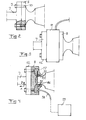
- the region of the tool flange in an industrial robot according to a first preferred embodiment of the invention is schematically illustrated in fig 4.
- the tool flange 8 is an integral part with a carrier 13 in the form of an axle pin which may be connected to a fork defining the axis 5 indicated on the robot shown in fig 1.
- the tool flange with the carrier 13 may have substantially the same shape as for a corresponding robot having no sensor means.
- the sensor means comprises sensor members 14, 15 in the form of tensiometers arranged on the carrier 13 and adapted to sense forces and/or torques applied to the carrier 13 and by that to the tool flange 8 and the tool 7.
- These tensiometers may for example be silicon strain gauges of the type changing the resistivity when extended or compressed or the sensor members may be in the form of piezo resistive elements.
- the sensor members 14, 15 shown in the figure may for example be adapted to measure forces in directions enabling calculation of for instance the force on the tool in the direction according to the arrow x and the torque with respect to the direction according to the arrow y. More sensor members than those shown in this figure may be applied to the carrier 13.
- the sensor members are connected to an electronic arrangement 16 forming an interface between the sensor members and an output signal to a unit 19 controlling the operation of the robot.
- the electronic arrangement may be arranged on a printed circuit card built into the tool flange.
- the printed circuit card and the sensor members may be embedded into a protecting plastic layer 17.
- a cable 18 is connected to the electronic arrangement for delivering measurement results from the sensor members to the control unit 19 schematically indicated controlling the operation of the robot.
- the sensor means may also be provided with electrical energy through said cable 18 when necessary.
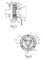
- Fig 5 and 6 illustrate a region of the tool flange of an industrial robot according to a second embodiment of the present invention.
- the tool flange 8 is in this embodiment slightly modified with respect to a conventional tool flange by having an outer ring 20 provided with tool securing means in the form of threaded holes 10, an inner hub 21 forming said carrier of the tool flange in the form of an axle pin as in the embodiment according to fig. 4, and substantially rigid spokes 22 interconnecting the hub and the ring.
- Sensor members 23-28 are arranged on the spokes for sensing forces and torques applied to the tool 7 secured to the tool flange 8.
- the sensor members are strain gauges arranged in couples with an angular distribution around the centre axis of the tool flange of 120° and with the sensors in each couple arranged perpendicular to each other.
- the sensor members may in this way sense forces for determining forces according to three degrees of freedom and torques according to three degrees of freedom, so that all forces and torques applied on the tool/tool flange may be determined.
- the spokes and the sensor members are here together with an electronic arrangement 16 embedded in a protecting plastic layer 17 as in the embodiment according to fig 4.
- Other "deformable" parts than spokes such as for example a membrane-like deformation zone, are also possible for the application of tensiometers for measuring forces and/or torques.
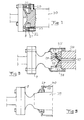
- Fig 7 illustrates a region of the tool flange of an industrial robot according to a third embodiment of the present invention.
- This embodiment differs from that according to fig 5 mainly by the fact that it is provided with an overload protection ensuring that the deformation of the spokes will not exceed a predetermined level. This is ensured by arranging preferably three or more radially extending pins 29 evenly distributed around the axle 30. These pins are arranged with a play 31 with respect to a ring 32 secured to the tool flange 8. This ring 32 is also arranged with a radial play 33 with respect to the axle 30. These plays 31, 33 define the maximum deformation of the tool flange with spokes allowed. The considerably smaller cross-section area of the spokes 22 with respect to the hub 21 results in deformations of the hub being neglectable in comparison with deformations of the spokes.
- Fig 8 illustrates a region of the tool flange 8 of an industrial robot according to a fourth embodiment of the present invention, in which the sensor members 23-28 (not all of them are visible in the figure) are arranged in a specially designed axle 34.
- This axle includes six so-called kinematic links 35 interconnecting the carrier of the tool flange 8 with the axle itself.
- the sensor members are arranged on these kinematic links and are through wires 36 connected to a cable 37 extending inside the axle 34 to a said control unit of the robot.
- a casing 38 is arranged for protecting the link arrangement.
- Fig 9 illustrates a region of the tool flange 8 of an industrial robot according a fifth embodiment of the present invention.
- the axle 39 carrying the tool flange 8 is in this case rigidly connected to the tool flange.
- Six sensor members are arranged in couples with a distribution of 120o inside the bearing housing 40 of the axle for measuring deformation of the bearing housing and by that determining the forces and/or torques acting on the axle 39 and by that on the tool.
- Figs 8 and 9 illustrates that "region” in the expression “sensor means is built into the structure of the robot in the region of the tool flange” is to be interpreted to also include location of the sensor members at an end position of an axle carrying the tool flange.
- an industrial robot useful for applications requiring force and/or torque sensors is according to the present invention obtained while saving considerable costs with respect to such robots already known.
- a robot of this type may very well be used for carrying out assembly works within the field of electronics, automotive industry and household appliances. It may also be used for polishing and grinding works, such as carried out on faucets and turbine blades. Different types of milling and cleaning works are also possible applications.
- friction stir welding for example within the automotive and aircraft industry, are other possible applications.
- the number of the sensor members and the position thereof may be different than shown in the figures as long as they are built into the structure of the robot in the region of the tool flange. "Built into the structure of the robot” means that the sensor means are located within this structure and not located externally to this structure by being arranged between the tool flange and the tool or externally of the tool flange.
- the sensor members may also comprise tensiometers based on capacitance changes of semiconductor components.
- tool flange is to be interpreted as a tool attachment which may have many different shapes, and it has not to have a circular cross-section.
- Ring as used in the claims and in the disclosure above does also comprise other shapes than circular, such as different type of polygons, for instance a square.
- An electronic arrangement as shown in figs 4 and 5 may also be arranged in the other embodiments described above.
Landscapes
- Engineering & Computer Science (AREA)
- Human Computer Interaction (AREA)
- Robotics (AREA)
- Mechanical Engineering (AREA)
- Force Measurement Appropriate To Specific Purposes (AREA)
- Manipulator (AREA)
Priority Applications (7)
| Application Number | Priority Date | Filing Date | Title |
|---|---|---|---|
| EP05108539A EP1764192B1 (de) | 2005-09-16 | 2005-09-16 | Industrieroboter mit Sensormitteln im Bereich eines Werkzeugflansches |
| ES05108539T ES2335352T3 (es) | 2005-09-16 | 2005-09-16 | Un robot industrial con medios detectores en la region de una brida de herramienta. |
| DE602005017894T DE602005017894D1 (de) | 2005-09-16 | 2005-09-16 | Industrieroboter mit Sensormitteln im Bereich eines Werkzeugflansches |
| AT05108539T ATE449672T1 (de) | 2005-09-16 | 2005-09-16 | Industrieroboter mit sensormitteln im bereich eines werkzeugflansches |
| US11/991,103 US7707893B2 (en) | 2005-09-16 | 2006-09-12 | Industrial robot |
| CN2006800337131A CN101277794B (zh) | 2005-09-16 | 2006-09-12 | 工业机器人 |
| PCT/EP2006/066276 WO2007031514A1 (en) | 2005-09-16 | 2006-09-12 | An industrial robot |
Applications Claiming Priority (1)
| Application Number | Priority Date | Filing Date | Title |
|---|---|---|---|
| EP05108539A EP1764192B1 (de) | 2005-09-16 | 2005-09-16 | Industrieroboter mit Sensormitteln im Bereich eines Werkzeugflansches |
Publications (2)
| Publication Number | Publication Date |
|---|---|
| EP1764192A1 true EP1764192A1 (de) | 2007-03-21 |
| EP1764192B1 EP1764192B1 (de) | 2009-11-25 |
Family
ID=35311132
Family Applications (1)
| Application Number | Title | Priority Date | Filing Date |
|---|---|---|---|
| EP05108539A Expired - Lifetime EP1764192B1 (de) | 2005-09-16 | 2005-09-16 | Industrieroboter mit Sensormitteln im Bereich eines Werkzeugflansches |
Country Status (7)
| Country | Link |
|---|---|
| US (1) | US7707893B2 (de) |
| EP (1) | EP1764192B1 (de) |
| CN (1) | CN101277794B (de) |
| AT (1) | ATE449672T1 (de) |
| DE (1) | DE602005017894D1 (de) |
| ES (1) | ES2335352T3 (de) |
| WO (1) | WO2007031514A1 (de) |
Cited By (7)
| Publication number | Priority date | Publication date | Assignee | Title |
|---|---|---|---|---|
| WO2015102552A1 (en) * | 2013-12-31 | 2015-07-09 | Ozyegin Universitesi | The method of processing multidimensional objects and large and curved surfaces using chemical and mechanical nano structuring method and configuration of robotic arm employed in realizing this method |
| WO2019238975A1 (en) * | 2018-06-15 | 2019-12-19 | Universal Robots A/S | Dual mode free-drive of robot arm |
| CN112629727A (zh) * | 2020-12-14 | 2021-04-09 | 大连理工大学 | 环形抛光过程中的限位支撑及摩擦力在线监测一体化装置 |
| US11872700B2 (en) | 2019-04-26 | 2024-01-16 | Fanuc Corporation | Robot with a torque sensor and a force sensor |
| US12296485B2 (en) | 2019-10-22 | 2025-05-13 | Universal Robots A/S | Robot arm with adaptive three-dimensional boundary in free-drive |
| US12384019B2 (en) | 2019-10-22 | 2025-08-12 | Universal Robots A/S | Safe activation of free-drive mode of robot arm |
| US12397414B2 (en) | 2019-10-22 | 2025-08-26 | Universal Robots A/S | Maintaining free-drive mode of robot arm for period of time |
Families Citing this family (15)
| Publication number | Priority date | Publication date | Assignee | Title |
|---|---|---|---|---|
| CN102317750B (zh) * | 2009-02-06 | 2015-07-22 | Abb股份公司 | 多轴线力和扭矩传感器的组及组装方法 |
| JP5353500B2 (ja) * | 2009-07-08 | 2013-11-27 | 株式会社安川電機 | ロボット |
| JP2011200943A (ja) * | 2010-03-24 | 2011-10-13 | Canon Inc | 力制御ロボット |
| JP6329239B2 (ja) | 2013-03-12 | 2018-05-23 | ストライカー・コーポレイション | 力及びトルクを測定するためのセンサ組立体及び方法 |
| US9884426B2 (en) | 2013-06-27 | 2018-02-06 | De-Sta-Co Europe Gmbh | Boom utilized in a geometric end effector system |
| US10591373B2 (en) * | 2013-08-01 | 2020-03-17 | Mts Systems Corporation | Load transducer having a biasing assembly |
| JP2017172983A (ja) * | 2016-03-18 | 2017-09-28 | 株式会社安川電機 | ロボット及びトルクセンサ |
| US10295418B1 (en) * | 2016-03-29 | 2019-05-21 | X Development Llc | Factory-calibrated multi-spoke strain sensor system |
| DE102016216902A1 (de) * | 2016-09-06 | 2018-03-08 | Deckel Maho Pfronten Gmbh | Werkzeugmaschine zur spanenden Bearbeitung eines Werkstücks sowie Spindelträgerbaugruppe zum Einsatz an einer derartigen Werkzeugmaschine |
| DE202016008595U1 (de) * | 2016-10-17 | 2018-07-26 | Franka Emlka Gmbh | Drehmomentsensorvorrichtung zum Erfassen von Drehmomenten |
| US10456858B2 (en) | 2018-03-30 | 2019-10-29 | Esab Ab | Welding head for friction stir welding |
| CN112368116B (zh) * | 2018-06-15 | 2025-03-21 | 优傲机器人公司 | 附接到机器人臂的有效载荷的估计 |
| WO2021117855A1 (ja) * | 2019-12-13 | 2021-06-17 | 長野計器株式会社 | トルクセンサ |
| CN114688951B (zh) * | 2022-03-30 | 2024-12-31 | 湖南腾智机电有限责任公司 | 一种隔膜泵膜片最大变形定位工装 |
| AT528436A1 (de) * | 2024-06-18 | 2026-01-15 | Trumpf Maschinen Austria Gmbh & Co Kg | Messvorrichtung für einen Handhabungsroboter einer Biegemaschine |
Citations (6)
| Publication number | Priority date | Publication date | Assignee | Title |
|---|---|---|---|---|
| JPS60164367A (ja) * | 1984-02-07 | 1985-08-27 | Nec Corp | 触覚センサ |
| JPS6259826A (ja) | 1985-09-10 | 1987-03-16 | Omron Tateisi Electronics Co | 力検出装置 |
| JPS6388417A (ja) * | 1986-09-30 | 1988-04-19 | Kawasaki Steel Corp | 力測定装置 |
| JPH05187940A (ja) * | 1992-01-14 | 1993-07-27 | Fujitsu Ltd | 力検出装置とその方法 |
| JPH0683435A (ja) | 1992-09-04 | 1994-03-25 | Meidensha Corp | ロボットの教示方法 |
| US5513536A (en) | 1993-01-28 | 1996-05-07 | Robert Bosch Gmbh | Pressure, force and torque measuring device |
Family Cites Families (6)
| Publication number | Priority date | Publication date | Assignee | Title |
|---|---|---|---|---|
| US4818173A (en) * | 1983-04-12 | 1989-04-04 | Polaroid Corporation | Robot arm member relative movement sensing apparatus |
| DE69219255T2 (de) * | 1991-08-30 | 1997-08-07 | Canon Kk | Handgreifmechanismus für einen Roboter |
| US5490427A (en) * | 1994-10-17 | 1996-02-13 | Fanuc Usa Corporation | Six axis force sensor employing multiple shear strain gages |
| JP2000354989A (ja) * | 1999-06-16 | 2000-12-26 | Fanuc Ltd | 自動刃具交換装置 |
| CN2591559Y (zh) * | 2002-12-30 | 2003-12-10 | 北京航空航天大学 | 接触式物体位姿测量装置 |
| DE10304019A1 (de) * | 2003-02-01 | 2004-11-04 | Kuka Roboter Gmbh | Verfahren zum Überwachen einer Maschine und derartige Maschine, insbesondere Roboter |
-
2005
- 2005-09-16 AT AT05108539T patent/ATE449672T1/de not_active IP Right Cessation
- 2005-09-16 EP EP05108539A patent/EP1764192B1/de not_active Expired - Lifetime
- 2005-09-16 DE DE602005017894T patent/DE602005017894D1/de not_active Expired - Lifetime
- 2005-09-16 ES ES05108539T patent/ES2335352T3/es not_active Expired - Lifetime
-
2006
- 2006-09-12 WO PCT/EP2006/066276 patent/WO2007031514A1/en not_active Ceased
- 2006-09-12 CN CN2006800337131A patent/CN101277794B/zh not_active Expired - Fee Related
- 2006-09-12 US US11/991,103 patent/US7707893B2/en not_active Expired - Fee Related
Patent Citations (6)
| Publication number | Priority date | Publication date | Assignee | Title |
|---|---|---|---|---|
| JPS60164367A (ja) * | 1984-02-07 | 1985-08-27 | Nec Corp | 触覚センサ |
| JPS6259826A (ja) | 1985-09-10 | 1987-03-16 | Omron Tateisi Electronics Co | 力検出装置 |
| JPS6388417A (ja) * | 1986-09-30 | 1988-04-19 | Kawasaki Steel Corp | 力測定装置 |
| JPH05187940A (ja) * | 1992-01-14 | 1993-07-27 | Fujitsu Ltd | 力検出装置とその方法 |
| JPH0683435A (ja) | 1992-09-04 | 1994-03-25 | Meidensha Corp | ロボットの教示方法 |
| US5513536A (en) | 1993-01-28 | 1996-05-07 | Robert Bosch Gmbh | Pressure, force and torque measuring device |
Non-Patent Citations (5)
| Title |
|---|
| PATENT ABSTRACTS OF JAPAN vol. 009, no. 332 (E - 370) 26 December 1985 (1985-12-26) * |
| PATENT ABSTRACTS OF JAPAN vol. 011, no. 253 (P - 606) 18 August 1987 (1987-08-18) * |
| PATENT ABSTRACTS OF JAPAN vol. 012, no. 327 (P - 753) 6 September 1988 (1988-09-06) * |
| PATENT ABSTRACTS OF JAPAN vol. 017, no. 609 (P - 1640) 9 November 1993 (1993-11-09) * |
| PATENT ABSTRACTS OF JAPAN vol. 018, no. 343 (P - 1761) 28 June 1994 (1994-06-28) * |
Cited By (9)
| Publication number | Priority date | Publication date | Assignee | Title |
|---|---|---|---|---|
| WO2015102552A1 (en) * | 2013-12-31 | 2015-07-09 | Ozyegin Universitesi | The method of processing multidimensional objects and large and curved surfaces using chemical and mechanical nano structuring method and configuration of robotic arm employed in realizing this method |
| WO2019238975A1 (en) * | 2018-06-15 | 2019-12-19 | Universal Robots A/S | Dual mode free-drive of robot arm |
| CN112352206A (zh) * | 2018-06-15 | 2021-02-09 | 优傲机器人公司 | 机器人臂的双模自由驱动 |
| US11839979B2 (en) | 2018-06-15 | 2023-12-12 | Universal Robots A/S | Dual mode free-drive of robot arm |
| US11872700B2 (en) | 2019-04-26 | 2024-01-16 | Fanuc Corporation | Robot with a torque sensor and a force sensor |
| US12296485B2 (en) | 2019-10-22 | 2025-05-13 | Universal Robots A/S | Robot arm with adaptive three-dimensional boundary in free-drive |
| US12384019B2 (en) | 2019-10-22 | 2025-08-12 | Universal Robots A/S | Safe activation of free-drive mode of robot arm |
| US12397414B2 (en) | 2019-10-22 | 2025-08-26 | Universal Robots A/S | Maintaining free-drive mode of robot arm for period of time |
| CN112629727A (zh) * | 2020-12-14 | 2021-04-09 | 大连理工大学 | 环形抛光过程中的限位支撑及摩擦力在线监测一体化装置 |
Also Published As
| Publication number | Publication date |
|---|---|
| ATE449672T1 (de) | 2009-12-15 |
| CN101277794B (zh) | 2011-08-10 |
| US7707893B2 (en) | 2010-05-04 |
| CN101277794A (zh) | 2008-10-01 |
| EP1764192B1 (de) | 2009-11-25 |
| ES2335352T3 (es) | 2010-03-25 |
| DE602005017894D1 (de) | 2010-01-07 |
| WO2007031514A1 (en) | 2007-03-22 |
| US20090088899A1 (en) | 2009-04-02 |
Similar Documents
| Publication | Publication Date | Title |
|---|---|---|
| US7707893B2 (en) | Industrial robot | |
| KR102080426B1 (ko) | 4개 미만의 빔 표면 상에 계측기기를 갖는 힘/토크 센서 | |
| KR102488210B1 (ko) | 사형 또는 나선형 변형 가능한 빔 및 과부하 빔을 갖는 힘/토크 센서 | |
| KR101293984B1 (ko) | 스트레인게이지 타입의 힘-토크 센서 및 그 제조 방법 | |
| EP0579722B1 (de) | Axialkompakter Drehmomentwandler | |
| US8776616B2 (en) | Multiaxial force-torque sensors | |
| JP2018059854A (ja) | 変位測定装置、ロボット、ロボットアーム及び物品の製造方法 | |
| CN207556719U (zh) | 扭矩传感器装置、机器人的机械手和机器人 | |
| US10184848B2 (en) | Sensor arrangement for indirect detection of a torque of a rotatably mounted shaft | |
| EP3971546B1 (de) | Kraftmesszelle | |
| EP3553484B1 (de) | Drehmomentsensor | |
| EP3822603A1 (de) | Drehmomentsensor | |
| EP0504731A2 (de) | Vorrichtung zur Messung der Einwirkungskraft auf ein Rad und Vorrichtung zur Messung von Strukturbelastung | |
| KR20190046216A (ko) | 관절토크센서를 구비하는 로봇 관절 유닛 | |
| KR102072492B1 (ko) | 토크 센서 | |
| KR20120119172A (ko) | 다축 힘토크 센서 | |
| JP7692863B2 (ja) | 力覚センサ | |
| Qi et al. | Design of a ring-type bearingless torque sensor with low crosstalk error | |
| JP7305364B2 (ja) | 多軸センサ | |
| JPH0641892B2 (ja) | 荷重検出器 | |
| US10295418B1 (en) | Factory-calibrated multi-spoke strain sensor system | |
| Chen et al. | Design and implementation of a PCB-based torque sensor with a spiral sensing pattern | |
| EP4722673A1 (de) | Kraft-/drehmomentsensorvorrichtung für ein kraft-/drehmomentsensormittel sowie kraft-/drehmomentsensormittel | |
| JPH0577253B2 (de) | ||
| EP4367487B1 (de) | Eine messzelle um eine kraft zu detektieren, ein system um eine last zu handhaben und ein verfahren um die grösse einer kraft zu berechnen |
Legal Events
| Date | Code | Title | Description |
|---|---|---|---|
| PUAI | Public reference made under article 153(3) epc to a published international application that has entered the european phase |
Free format text: ORIGINAL CODE: 0009012 |
|
| AK | Designated contracting states |
Kind code of ref document: A1 Designated state(s): AT BE BG CH CY CZ DE DK EE ES FI FR GB GR HU IE IS IT LI LT LU LV MC NL PL PT RO SE SI SK TR |
|
| AX | Request for extension of the european patent |
Extension state: AL BA HR MK YU |
|
| 17P | Request for examination filed |
Effective date: 20070913 |
|
| AKX | Designation fees paid |
Designated state(s): AT BE BG CH CY CZ DE DK EE ES FI FR GB GR HU IE IS IT LI LT LU LV MC NL PL PT RO SE SI SK TR |
|
| 17Q | First examination report despatched |
Effective date: 20071214 |
|
| GRAP | Despatch of communication of intention to grant a patent |
Free format text: ORIGINAL CODE: EPIDOSNIGR1 |
|
| GRAS | Grant fee paid |
Free format text: ORIGINAL CODE: EPIDOSNIGR3 |
|
| GRAA | (expected) grant |
Free format text: ORIGINAL CODE: 0009210 |
|
| AK | Designated contracting states |
Kind code of ref document: B1 Designated state(s): AT BE BG CH CY CZ DE DK EE ES FI FR GB GR HU IE IS IT LI LT LU LV MC NL PL PT RO SE SI SK TR |
|
| REG | Reference to a national code |
Ref country code: GB Ref legal event code: FG4D |
|
| REG | Reference to a national code |
Ref country code: CH Ref legal event code: EP |
|
| REG | Reference to a national code |
Ref country code: IE Ref legal event code: FG4D |
|
| REF | Corresponds to: |
Ref document number: 602005017894 Country of ref document: DE Date of ref document: 20100107 Kind code of ref document: P |
|
| REG | Reference to a national code |
Ref country code: ES Ref legal event code: FG2A Ref document number: 2335352 Country of ref document: ES Kind code of ref document: T3 |
|
| REG | Reference to a national code |
Ref country code: NL Ref legal event code: VDEP Effective date: 20091125 |
|
| LTIE | Lt: invalidation of european patent or patent extension |
Effective date: 20091125 |
|
| PG25 | Lapsed in a contracting state [announced via postgrant information from national office to epo] |
Ref country code: LT Free format text: LAPSE BECAUSE OF FAILURE TO SUBMIT A TRANSLATION OF THE DESCRIPTION OR TO PAY THE FEE WITHIN THE PRESCRIBED TIME-LIMIT Effective date: 20091125 Ref country code: FI Free format text: LAPSE BECAUSE OF FAILURE TO SUBMIT A TRANSLATION OF THE DESCRIPTION OR TO PAY THE FEE WITHIN THE PRESCRIBED TIME-LIMIT Effective date: 20091125 Ref country code: IS Free format text: LAPSE BECAUSE OF FAILURE TO SUBMIT A TRANSLATION OF THE DESCRIPTION OR TO PAY THE FEE WITHIN THE PRESCRIBED TIME-LIMIT Effective date: 20100325 Ref country code: PT Free format text: LAPSE BECAUSE OF FAILURE TO SUBMIT A TRANSLATION OF THE DESCRIPTION OR TO PAY THE FEE WITHIN THE PRESCRIBED TIME-LIMIT Effective date: 20100325 Ref country code: SE Free format text: LAPSE BECAUSE OF FAILURE TO SUBMIT A TRANSLATION OF THE DESCRIPTION OR TO PAY THE FEE WITHIN THE PRESCRIBED TIME-LIMIT Effective date: 20091125 |
|
| PG25 | Lapsed in a contracting state [announced via postgrant information from national office to epo] |
Ref country code: PL Free format text: LAPSE BECAUSE OF FAILURE TO SUBMIT A TRANSLATION OF THE DESCRIPTION OR TO PAY THE FEE WITHIN THE PRESCRIBED TIME-LIMIT Effective date: 20091125 Ref country code: CY Free format text: LAPSE BECAUSE OF FAILURE TO SUBMIT A TRANSLATION OF THE DESCRIPTION OR TO PAY THE FEE WITHIN THE PRESCRIBED TIME-LIMIT Effective date: 20091125 Ref country code: SI Free format text: LAPSE BECAUSE OF FAILURE TO SUBMIT A TRANSLATION OF THE DESCRIPTION OR TO PAY THE FEE WITHIN THE PRESCRIBED TIME-LIMIT Effective date: 20091125 Ref country code: LV Free format text: LAPSE BECAUSE OF FAILURE TO SUBMIT A TRANSLATION OF THE DESCRIPTION OR TO PAY THE FEE WITHIN THE PRESCRIBED TIME-LIMIT Effective date: 20091125 |
|
| PG25 | Lapsed in a contracting state [announced via postgrant information from national office to epo] |
Ref country code: BE Free format text: LAPSE BECAUSE OF FAILURE TO SUBMIT A TRANSLATION OF THE DESCRIPTION OR TO PAY THE FEE WITHIN THE PRESCRIBED TIME-LIMIT Effective date: 20091125 Ref country code: AT Free format text: LAPSE BECAUSE OF FAILURE TO SUBMIT A TRANSLATION OF THE DESCRIPTION OR TO PAY THE FEE WITHIN THE PRESCRIBED TIME-LIMIT Effective date: 20091125 |
|
| PG25 | Lapsed in a contracting state [announced via postgrant information from national office to epo] |
Ref country code: EE Free format text: LAPSE BECAUSE OF FAILURE TO SUBMIT A TRANSLATION OF THE DESCRIPTION OR TO PAY THE FEE WITHIN THE PRESCRIBED TIME-LIMIT Effective date: 20091125 Ref country code: DK Free format text: LAPSE BECAUSE OF FAILURE TO SUBMIT A TRANSLATION OF THE DESCRIPTION OR TO PAY THE FEE WITHIN THE PRESCRIBED TIME-LIMIT Effective date: 20091125 Ref country code: NL Free format text: LAPSE BECAUSE OF FAILURE TO SUBMIT A TRANSLATION OF THE DESCRIPTION OR TO PAY THE FEE WITHIN THE PRESCRIBED TIME-LIMIT Effective date: 20091125 Ref country code: BG Free format text: LAPSE BECAUSE OF FAILURE TO SUBMIT A TRANSLATION OF THE DESCRIPTION OR TO PAY THE FEE WITHIN THE PRESCRIBED TIME-LIMIT Effective date: 20100225 Ref country code: RO Free format text: LAPSE BECAUSE OF FAILURE TO SUBMIT A TRANSLATION OF THE DESCRIPTION OR TO PAY THE FEE WITHIN THE PRESCRIBED TIME-LIMIT Effective date: 20091125 |
|
| PG25 | Lapsed in a contracting state [announced via postgrant information from national office to epo] |
Ref country code: CZ Free format text: LAPSE BECAUSE OF FAILURE TO SUBMIT A TRANSLATION OF THE DESCRIPTION OR TO PAY THE FEE WITHIN THE PRESCRIBED TIME-LIMIT Effective date: 20091125 Ref country code: SK Free format text: LAPSE BECAUSE OF FAILURE TO SUBMIT A TRANSLATION OF THE DESCRIPTION OR TO PAY THE FEE WITHIN THE PRESCRIBED TIME-LIMIT Effective date: 20091125 |
|
| PLBE | No opposition filed within time limit |
Free format text: ORIGINAL CODE: 0009261 |
|
| STAA | Information on the status of an ep patent application or granted ep patent |
Free format text: STATUS: NO OPPOSITION FILED WITHIN TIME LIMIT |
|
| PG25 | Lapsed in a contracting state [announced via postgrant information from national office to epo] |
Ref country code: GR Free format text: LAPSE BECAUSE OF FAILURE TO SUBMIT A TRANSLATION OF THE DESCRIPTION OR TO PAY THE FEE WITHIN THE PRESCRIBED TIME-LIMIT Effective date: 20100226 |
|
| 26N | No opposition filed |
Effective date: 20100826 |
|
| PGFP | Annual fee paid to national office [announced via postgrant information from national office to epo] |
Ref country code: FR Payment date: 20100921 Year of fee payment: 6 |
|
| PG25 | Lapsed in a contracting state [announced via postgrant information from national office to epo] |
Ref country code: MC Free format text: LAPSE BECAUSE OF NON-PAYMENT OF DUE FEES Effective date: 20100930 |
|
| REG | Reference to a national code |
Ref country code: CH Ref legal event code: PL |
|
| GBPC | Gb: european patent ceased through non-payment of renewal fee |
Effective date: 20100916 |
|
| PG25 | Lapsed in a contracting state [announced via postgrant information from national office to epo] |
Ref country code: IE Free format text: LAPSE BECAUSE OF NON-PAYMENT OF DUE FEES Effective date: 20100916 Ref country code: LI Free format text: LAPSE BECAUSE OF NON-PAYMENT OF DUE FEES Effective date: 20100930 Ref country code: CH Free format text: LAPSE BECAUSE OF NON-PAYMENT OF DUE FEES Effective date: 20100930 |
|
| PG25 | Lapsed in a contracting state [announced via postgrant information from national office to epo] |
Ref country code: GB Free format text: LAPSE BECAUSE OF NON-PAYMENT OF DUE FEES Effective date: 20100916 |
|
| REG | Reference to a national code |
Ref country code: FR Ref legal event code: ST Effective date: 20120531 |
|
| PG25 | Lapsed in a contracting state [announced via postgrant information from national office to epo] |
Ref country code: FR Free format text: LAPSE BECAUSE OF NON-PAYMENT OF DUE FEES Effective date: 20110930 |
|
| PG25 | Lapsed in a contracting state [announced via postgrant information from national office to epo] |
Ref country code: HU Free format text: LAPSE BECAUSE OF FAILURE TO SUBMIT A TRANSLATION OF THE DESCRIPTION OR TO PAY THE FEE WITHIN THE PRESCRIBED TIME-LIMIT Effective date: 20100526 Ref country code: LU Free format text: LAPSE BECAUSE OF NON-PAYMENT OF DUE FEES Effective date: 20100916 |
|
| PG25 | Lapsed in a contracting state [announced via postgrant information from national office to epo] |
Ref country code: TR Free format text: LAPSE BECAUSE OF FAILURE TO SUBMIT A TRANSLATION OF THE DESCRIPTION OR TO PAY THE FEE WITHIN THE PRESCRIBED TIME-LIMIT Effective date: 20091125 |
|
| PGFP | Annual fee paid to national office [announced via postgrant information from national office to epo] |
Ref country code: ES Payment date: 20121004 Year of fee payment: 8 |
|
| PGFP | Annual fee paid to national office [announced via postgrant information from national office to epo] |
Ref country code: IT Payment date: 20130912 Year of fee payment: 9 |
|
| REG | Reference to a national code |
Ref country code: ES Ref legal event code: FD2A Effective date: 20150709 |
|
| PG25 | Lapsed in a contracting state [announced via postgrant information from national office to epo] |
Ref country code: ES Free format text: LAPSE BECAUSE OF NON-PAYMENT OF DUE FEES Effective date: 20130917 |
|
| PG25 | Lapsed in a contracting state [announced via postgrant information from national office to epo] |
Ref country code: IT Free format text: LAPSE BECAUSE OF NON-PAYMENT OF DUE FEES Effective date: 20140916 |
|
| PGFP | Annual fee paid to national office [announced via postgrant information from national office to epo] |
Ref country code: DE Payment date: 20160921 Year of fee payment: 12 |
|
| REG | Reference to a national code |
Ref country code: DE Ref legal event code: R119 Ref document number: 602005017894 Country of ref document: DE |
|
| PG25 | Lapsed in a contracting state [announced via postgrant information from national office to epo] |
Ref country code: DE Free format text: LAPSE BECAUSE OF NON-PAYMENT OF DUE FEES Effective date: 20180404 |