EP1764231A2 - Dispositif d'application d'adhésive avec buses - Google Patents
Dispositif d'application d'adhésive avec buses Download PDFInfo
- Publication number
- EP1764231A2 EP1764231A2 EP06120570A EP06120570A EP1764231A2 EP 1764231 A2 EP1764231 A2 EP 1764231A2 EP 06120570 A EP06120570 A EP 06120570A EP 06120570 A EP06120570 A EP 06120570A EP 1764231 A2 EP1764231 A2 EP 1764231A2
- Authority
- EP
- European Patent Office
- Prior art keywords
- adhesive
- application
- application system
- nozzle opening
- opening
- Prior art date
- Legal status (The legal status is an assumption and is not a legal conclusion. Google has not performed a legal analysis and makes no representation as to the accuracy of the status listed.)
- Withdrawn
Links
Images




Classifications
-
- B—PERFORMING OPERATIONS; TRANSPORTING
- B42—BOOKBINDING; ALBUMS; FILES; SPECIAL PRINTED MATTER
- B42C—BOOKBINDING
- B42C9/00—Applying glue or adhesive peculiar to bookbinding
- B42C9/0006—Applying glue or adhesive peculiar to bookbinding by applying adhesive to a stack of sheets
-
- B—PERFORMING OPERATIONS; TRANSPORTING
- B05—SPRAYING OR ATOMISING IN GENERAL; APPLYING FLUENT MATERIALS TO SURFACES, IN GENERAL
- B05C—APPARATUS FOR APPLYING FLUENT MATERIALS TO SURFACES, IN GENERAL
- B05C5/00—Apparatus in which liquid or other fluent material is projected, poured or allowed to flow on to the surface of the work
- B05C5/001—Apparatus in which liquid or other fluent material is projected, poured or allowed to flow on to the surface of the work incorporating means for heating or cooling the liquid or other fluent material
-
- B—PERFORMING OPERATIONS; TRANSPORTING
- B05—SPRAYING OR ATOMISING IN GENERAL; APPLYING FLUENT MATERIALS TO SURFACES, IN GENERAL
- B05C—APPARATUS FOR APPLYING FLUENT MATERIALS TO SURFACES, IN GENERAL
- B05C5/00—Apparatus in which liquid or other fluent material is projected, poured or allowed to flow on to the surface of the work
- B05C5/02—Apparatus in which liquid or other fluent material is projected, poured or allowed to flow on to the surface of the work the liquid or other fluent material being discharged through an outlet orifice by pressure, e.g. from an outlet device in contact or almost in contact, with the work
- B05C5/0225—Apparatus in which liquid or other fluent material is projected, poured or allowed to flow on to the surface of the work the liquid or other fluent material being discharged through an outlet orifice by pressure, e.g. from an outlet device in contact or almost in contact, with the work characterised by flow controlling means, e.g. valves, located proximate the outlet
- B05C5/0229—Apparatus in which liquid or other fluent material is projected, poured or allowed to flow on to the surface of the work the liquid or other fluent material being discharged through an outlet orifice by pressure, e.g. from an outlet device in contact or almost in contact, with the work characterised by flow controlling means, e.g. valves, located proximate the outlet the valve being a gate valve or a sliding valve
- B05C5/0233—Apparatus in which liquid or other fluent material is projected, poured or allowed to flow on to the surface of the work the liquid or other fluent material being discharged through an outlet orifice by pressure, e.g. from an outlet device in contact or almost in contact, with the work characterised by flow controlling means, e.g. valves, located proximate the outlet the valve being a gate valve or a sliding valve rotating valve, e.g. rotating perforated cylinder
-
- B—PERFORMING OPERATIONS; TRANSPORTING
- B05—SPRAYING OR ATOMISING IN GENERAL; APPLYING FLUENT MATERIALS TO SURFACES, IN GENERAL
- B05C—APPARATUS FOR APPLYING FLUENT MATERIALS TO SURFACES, IN GENERAL
- B05C5/00—Apparatus in which liquid or other fluent material is projected, poured or allowed to flow on to the surface of the work
- B05C5/02—Apparatus in which liquid or other fluent material is projected, poured or allowed to flow on to the surface of the work the liquid or other fluent material being discharged through an outlet orifice by pressure, e.g. from an outlet device in contact or almost in contact, with the work
- B05C5/0254—Coating heads with slot-shaped outlet
- B05C5/0258—Coating heads with slot-shaped outlet flow controlled, e.g. by a valve
-
- B—PERFORMING OPERATIONS; TRANSPORTING
- B05—SPRAYING OR ATOMISING IN GENERAL; APPLYING FLUENT MATERIALS TO SURFACES, IN GENERAL
- B05C—APPARATUS FOR APPLYING FLUENT MATERIALS TO SURFACES, IN GENERAL
- B05C5/00—Apparatus in which liquid or other fluent material is projected, poured or allowed to flow on to the surface of the work
- B05C5/02—Apparatus in which liquid or other fluent material is projected, poured or allowed to flow on to the surface of the work the liquid or other fluent material being discharged through an outlet orifice by pressure, e.g. from an outlet device in contact or almost in contact, with the work
- B05C5/0254—Coating heads with slot-shaped outlet
- B05C5/0266—Coating heads with slot-shaped outlet adjustable in length, e.g. for coating webs of different width
Definitions
- the invention relates to an application system for adhesive according to the preamble of patent claim 1.
- adhesive is either applied to a book spine using roller applicators or alternatively with application nozzles.
- the adhesive is dispersion adhesives, hot melt adhesives or dispersion / hot melt adhesive combinations.
- the adhesive polyurethane PUR for short
- PUR polyurethane
- This adhesive is also advantageous for poorer paper quality, with poorer paper quality meant as coated papers in which the proportion of coating ingredients outweighs the fiber content required for the strength, and also roughen poorer to expose the fiber for bonding.
- nozzle application systems are also increasingly being used, such as in the US Pat US Pat. No. 4,667,879 , of the European patent application EP 1 033 262 and the European patent application EP 550 913 shown. All of these publications are mean that after Because of the desire to vary the width of the adhesive trace. This is important for nozzles, since, unlike in a roller application system, the adhesive outside the surface to be bonded can not flow back into the system and so contamination of the system or a higher-level device can not be avoided if the nozzle is set too wide.
- the US 4,667,879 solves this problem of width adjustment of the adhesive track through a cylindrical adhesive chamber in which a cylindrical metering roller is arranged, wherein the cylindrical metering roller has a recess on the circumference, which has different lengths in the axial direction, in particular has the shape of a trapezoid.
- the cylindrical metering roller has a recess on the circumference, which has different lengths in the axial direction, in particular has the shape of a trapezoid.
- This device is particularly suitable for very long traces of glue, such as can be used in wood processing.
- the system is intended for regular hot glue, which does not show the problem of the ausreagierenden adhesive to the extent.
- a coating system for adhesive with a cylindrical adhesive chamber wherein within the cylindrical adhesive chamber, a cylindrical metering roller is arranged, wherein the cylindrical metering roller has a recess on the circumference, which has different length in the axial direction, such as a trapezoid, a rhombus , an oval or a triangle, wherein the recess of the cylindrical metering roller interacts with the application nozzle openings of the application system, wherein the length of the recess in the axial direction which is opposite theminutedüsenö Maschinen, the adhesive application width of theaiddüsenö réelle is substantially predetermined, with the characterizing features of claim 1 solved. Further features emerge from the subclaims and the following description of preferred embodiments.
- the application system according to the invention has closure means for the application nozzle opening.
- the closure means of the application nozzle opening is a two-part nozzle plate having at least one closure edge, wherein the closure edge is slidably disposed relative to the applicator nozzle opening, such that overlapping the closure edge and the applicator nozzle opening Adhesive flow can be interrupted.
- the two-part nozzle plate be designed such that both parts of the two-part nozzle plate are movable to bring the sealing edge on the applicator nozzle opening and close tightly or part of the two-part nozzle plate is stationary.
- the closure means of the application nozzle opening is a one-piece nozzle plate having at least one nozzle plate opening, wherein the nozzle plate opening is slidably disposed relative to the applicator nozzle opening, such that only at an at least partial overlap of the nozzle plate opening and the application nozzle opening can flow adhesive.
- the nozzle plate opening is slidably disposed relative to the applicator nozzle opening, such that only at an at least partial overlap of the nozzle plate opening and the application nozzle opening can flow adhesive.
- An advantage of using a one-piece or two-part nozzle plate is that this nozzle plate can be very thin and thus little space between the nozzle opening and the medium to which the adhesive is applied, such as a book block is needed.
- One possible adjusting means of the nozzle plate which realizes the displacement between the nozzle plate opening and the application nozzle opening, can be arranged further away from the application nozzle opening, at a location where more space is available for this purpose.
- the nozzle plate opening consists of a double row of mutually offset holes, through which the adhesive flows depending on the application width during application. This leads to a stabilization of the nozzle plate, because no continuous slot along the application width is required.
- a seal which terminates with the cylindrical adhesive chamber is arranged on the metering roller along the depression.
- the seal is advantageously such to ensure that it also protrudes into the applicator nozzle opening so far as to prevent a lateral wide flow of the adhesive in the nozzle.
- the application nozzle opening advantageously has a weakening at this point.
- a lubricating grease is applied in the side area between the cylindrical adhesive chamber and the metering roller outside the depression, which has high-viscosity properties at the temperature of the hot adhesive.
- the temperature at which PUR is processed is about 130 ° C.
- the metering roller and / or the cylindrical adhesive chamber is covered with adhesion-reducing materials or constructed of materials with low adhesion, such as PTFE (polytetrafluoroethylene, Teflon). This promotes the possibility of quickly cleaning the application system.
- adhesion-reducing materials such as PTFE (polytetrafluoroethylene, Teflon).
- the application head 10 of the application system 100 can be seen in section.
- the application head 10 has a cylindrical adhesive chamber 11, within which the metering roller 20 is arranged. Through an adhesive inlet opening 12, adhesive 2 is introduced into the adhesive chamber 11.
- the metering roller 20 is, as shown in Fig. 2, constructed such that it has a recess 22 on its periphery.
- This recess 22 may have different geometric shapes, such as a triangle, a trapezoid, a rhombus, an oval or other shape, these forms of the recess 22 is common that the width of the recess 22 is different in the axial direction.
- the recess 22 is bounded laterally by sealing rings 26a, 26b.
- 20 further sealing rings 26 b are mounted on the metering roll, which also complete the side portion 23 between the recess and the edge of the metering roller 20.
- a highly viscous lubricating grease is applied, especially one which is highly viscous at the operating temperature of the nozzle roller, for example at 130 ° C for PUR.
- the metering roller 20 is rotatable about its axis in the direction of the double arrow marked with the reference numeral 25.
- a drive 28 serves this purpose.
- At least one heating element 40 is arranged.
- a higher-level controller 50 controls both the drive 28 for adjusting the metering roller 20 and the control of the heating element 40 to keep the metering roller 20 at the desired operating temperature.
- the adhesive 2 flows into the recess 22 on the metering roller 20 and leaves the applicator head 10 through the applicator nozzle opening 16 to be applied as a glue trace 2 on a book spine of a book block 1.
- a weakening 14 is provided below the application nozzle opening 16, which reduces the thickness of the application head 10 in the region of the application nozzle opening 16 to a minimum.
- the sealing rings 26a come as close as possible to the application nozzle opening 16 in order to prevent the adhesive track 2 from flowing on the book block 1.
- a nozzle plate 32, 33 is arranged between the book block 1 and the application nozzle opening 16, a nozzle plate 32, 33 is arranged.
- An adjustment means 30, which is also controlled by the controller 50, is capable of displacing the nozzle plate 32, 33 relative to the applicator nozzle opening 16 such that opening or closing of the applicator nozzle opening 16 is possible so as to meter the adhesive 2 onto the book block 1 to ensure. In addition, this can complete the system 100 at rest against the outside atmosphere.
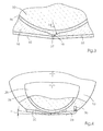
- Fig. 3 is a detail view of a two-part nozzle plate 33 is shown.
- the application nozzle opening 16 is closed by the closing edge 37 of the movable part of the two-part nozzle plate 33.
- an opening angle ⁇ is also shown, which is provided between the application plane and the two-part nozzle plate 33.
- a pull-wedge 36 which is used for sensitive adjustment and adjustment of the clear width of the gap in the two-part nozzle plate.
- FIGS. 5 and 6 show a further embodiment of the application device 100 according to the invention, wherein a one-piece nozzle plate 32 is attached above the application nozzle opening 16 by means of screws 35.
- a valve 18 is shown, which regulates the flow of adhesive into the adhesive chamber 11.
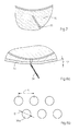
- the one-piece nozzle plate 32 has a slot 38, in a different embodiment shown in FIG. 8a a double row 39 consisting of spaced holes 39a of diameter D and distance A from center to center within a row, wherein the distance A is less than two distances D, so that over the entire width of the double row 39 adhesive 2 can flow.
- This embodiment with the holes 39a has a higher stability than a continuous slot 38.
- an opening angle ⁇ is also provided between the one-piece nozzle plate 32 and the application level, which prevents the adhesive trace 2 from coming into contact with the application head 10 after application to the book block 1.
- deviationating from circular holes 39a other shapes are conceivable, such as triangles or hexagonal openings.
- the one-piece nozzle plate 32 can be easily removed by loosening the screws 35 from the applicator head 10 to clean or replace it.
- the application system 100 has been described in particular in connection with the adhesive binding of book blocks 1, but can also be used in other applications in which a defined amount of adhesive must be applied in different widths to a surface, for example in wood processing.
Landscapes
- Coating Apparatus (AREA)
Applications Claiming Priority (1)
| Application Number | Priority Date | Filing Date | Title |
|---|---|---|---|
| DE200510044273 DE102005044273A1 (de) | 2005-09-16 | 2005-09-16 | Düsenauftragssystem für Klebstoff |
Publications (2)
| Publication Number | Publication Date |
|---|---|
| EP1764231A2 true EP1764231A2 (fr) | 2007-03-21 |
| EP1764231A3 EP1764231A3 (fr) | 2012-08-29 |
Family
ID=37507610
Family Applications (1)
| Application Number | Title | Priority Date | Filing Date |
|---|---|---|---|
| EP06120570A Withdrawn EP1764231A3 (fr) | 2005-09-16 | 2006-09-13 | Dispositif d'application d'adhésive avec buses |
Country Status (2)
| Country | Link |
|---|---|
| EP (1) | EP1764231A3 (fr) |
| DE (1) | DE102005044273A1 (fr) |
Cited By (2)
| Publication number | Priority date | Publication date | Assignee | Title |
|---|---|---|---|---|
| WO2011117676A1 (fr) * | 2010-03-24 | 2011-09-29 | New Bind Srl | Applicateur de colle pour machines à relier |
| WO2017209926A1 (fr) | 2016-05-31 | 2017-12-07 | 3M Innovative Properties Company | Systèmes de revêtement à matrice à cames |
Family Cites Families (9)
| Publication number | Priority date | Publication date | Assignee | Title |
|---|---|---|---|---|
| CH648497A5 (en) * | 1982-09-24 | 1985-03-29 | Billeter Kunststoffpulver Ag | Device for surface coating, directly or according to the transfer printing principle, a substrate |
| US4667879A (en) * | 1985-08-21 | 1987-05-26 | Nordson Corporation | Thermoplastic material applicator having an adjustable slot nozzle |
| JPS6268569A (ja) * | 1985-09-20 | 1987-03-28 | Meiji Kikai Seisakusho:Kk | 接着剤塗付具 |
| DE3804856A1 (de) * | 1988-02-17 | 1989-08-31 | Macon Gmbh Klebstoff Auftragsg | Vorrichtung zum flaechigen auftragen von leim oder dergleichen |
| US5271794A (en) * | 1992-01-09 | 1993-12-21 | Nordson Corporation | Adjustable width coating nozzle and side sealer |
| JP2917127B2 (ja) * | 1996-07-12 | 1999-07-12 | 井上金属工業株式会社 | 塗布装置 |
| EP1042074B1 (fr) * | 1997-12-22 | 2003-04-02 | Wolfgang Puffe | Tete d'application rotative |
| EP1033262A1 (fr) * | 1999-03-01 | 2000-09-06 | Sogno AG | Station d'encollage pour produits imprimés |
| DE10210748B4 (de) * | 2002-03-12 | 2015-06-18 | Nordson Corp. | Rotationsauftragskopf |
-
2005
- 2005-09-16 DE DE200510044273 patent/DE102005044273A1/de not_active Withdrawn
-
2006
- 2006-09-13 EP EP06120570A patent/EP1764231A3/fr not_active Withdrawn
Cited By (5)
| Publication number | Priority date | Publication date | Assignee | Title |
|---|---|---|---|---|
| WO2011117676A1 (fr) * | 2010-03-24 | 2011-09-29 | New Bind Srl | Applicateur de colle pour machines à relier |
| CN102933399A (zh) * | 2010-03-24 | 2013-02-13 | 4B-四邦有限责任公司 | 用于装订机的涂胶器 |
| WO2017209926A1 (fr) | 2016-05-31 | 2017-12-07 | 3M Innovative Properties Company | Systèmes de revêtement à matrice à cames |
| EP3463684A4 (fr) * | 2016-05-31 | 2020-01-22 | 3M Innovative Properties Company | Systèmes de revêtement à matrice à cames |
| US10882068B2 (en) | 2016-05-31 | 2021-01-05 | 3M Innovative Properties Company | Cam die coating systems |
Also Published As
| Publication number | Publication date |
|---|---|
| EP1764231A3 (fr) | 2012-08-29 |
| DE102005044273A1 (de) | 2007-03-29 |
Similar Documents
| Publication | Publication Date | Title |
|---|---|---|
| DE69215223T2 (de) | Düsen | |
| DE1696650C3 (de) | Verfahren und Vorrichtung zum Beschichten von bandförmigem Material mit einer erhitzten thermoplastischen Substanz | |
| DE3438380A1 (de) | Streicheinrichtung zur beschichtung laufender warenbahnen | |
| EP0850697A2 (fr) | Dispositif pour l'application de matériaux fluides sur un substrat, en particulier pour l'application intermittente de colles fluides | |
| DE102018120445B3 (de) | Filtriervorrichtung für hochviskose Medien | |
| EP0158220A2 (fr) | Cylindre pour calandre chauffé par un fluide de transfert de chaleur | |
| DE3931793A1 (de) | Ein geraet zur beschichtung einer fahrenden bahn | |
| EP0008705A1 (fr) | Extrudeuse à plusieurs vis dont la tête a un petit volume et dispositif pour échanger le tamis | |
| DE3513063C2 (fr) | ||
| DE2555669A1 (de) | Vorrichtung zum abstreifen ueberschuessiger streichmasse | |
| DE19722117C2 (de) | Beschichtung poröser Träger | |
| DE2935677C2 (de) | Vorrichtung zur Herstellung von einseitiger Wellpappe | |
| DE2350375B2 (de) | Misch- oder verteilventil | |
| EP0744220B1 (fr) | Buse à fente | |
| EP0266639B1 (fr) | Dispositif de commande de débit | |
| DE3530508A1 (de) | Vorrichtung zum auspressen von fliessfaehigen massen | |
| DE2359413C3 (de) | Vorrichtung zum Beschichten laufender Werkstoffbahnen aus Papier, Karton, Kunststoff o.dgl. | |
| DD231280A5 (de) | Streichkopf | |
| EP1764231A2 (fr) | Dispositif d'application d'adhésive avec buses | |
| EP0152921B1 (fr) | Dispositif de revêtement pour des matériaux en feuilles | |
| DE8812493U1 (de) | Schlitzdüse | |
| EP0166955B1 (fr) | Encrier pour machine rotative d'impression comportant un dispositif de dosage de l'encre | |
| WO1996002703A1 (fr) | Appareil limiteur lateral pour dispositif d'enduction a court temps de contact | |
| EP0056067B1 (fr) | Dispositif pour appliquer une couche mince d'une substance d'enduction sur une bande de matériau en mouvement | |
| DE10131825C1 (de) | Farbmesseranordnung an einem Farbkasten einer Druckmaschine |
Legal Events
| Date | Code | Title | Description |
|---|---|---|---|
| PUAI | Public reference made under article 153(3) epc to a published international application that has entered the european phase |
Free format text: ORIGINAL CODE: 0009012 |
|
| AK | Designated contracting states |
Kind code of ref document: A2 Designated state(s): AT BE BG CH CY CZ DE DK EE ES FI FR GB GR HU IE IS IT LI LT LU LV MC NL PL PT RO SE SI SK TR |
|
| AX | Request for extension of the european patent |
Extension state: AL BA HR MK YU |
|
| PUAL | Search report despatched |
Free format text: ORIGINAL CODE: 0009013 |
|
| AK | Designated contracting states |
Kind code of ref document: A3 Designated state(s): AT BE BG CH CY CZ DE DK EE ES FI FR GB GR HU IE IS IT LI LT LU LV MC NL PL PT RO SE SI SK TR |
|
| AX | Request for extension of the european patent |
Extension state: AL BA HR MK RS |
|
| RIC1 | Information provided on ipc code assigned before grant |
Ipc: B05C 1/10 20060101ALI20120723BHEP Ipc: B42C 9/00 20060101AFI20120723BHEP |
|
| AKY | No designation fees paid | ||
| REG | Reference to a national code |
Ref country code: DE Ref legal event code: R108 |
|
| REG | Reference to a national code |
Ref country code: DE Ref legal event code: R108 Effective date: 20130508 |
|
| STAA | Information on the status of an ep patent application or granted ep patent |
Free format text: STATUS: THE APPLICATION IS DEEMED TO BE WITHDRAWN |
|
| 18D | Application deemed to be withdrawn |
Effective date: 20130301 |