EP1764286A1 - Montant de baie ou pilier de carrosserie de véhicule - Google Patents
Montant de baie ou pilier de carrosserie de véhicule Download PDFInfo
- Publication number
- EP1764286A1 EP1764286A1 EP06017415A EP06017415A EP1764286A1 EP 1764286 A1 EP1764286 A1 EP 1764286A1 EP 06017415 A EP06017415 A EP 06017415A EP 06017415 A EP06017415 A EP 06017415A EP 1764286 A1 EP1764286 A1 EP 1764286A1
- Authority
- EP
- European Patent Office
- Prior art keywords
- profile
- roof frame
- pillar
- frame profile
- body pillar
- Prior art date
- Legal status (The legal status is an assumption and is not a legal conclusion. Google has not performed a legal analysis and makes no representation as to the accuracy of the status listed.)
- Granted
Links
Images


Classifications
-
- B—PERFORMING OPERATIONS; TRANSPORTING
- B62—LAND VEHICLES FOR TRAVELLING OTHERWISE THAN ON RAILS
- B62D—MOTOR VEHICLES; TRAILERS
- B62D25/00—Superstructure or monocoque structure sub-units; Parts or details thereof not otherwise provided for
- B62D25/04—Door pillars ; windshield pillars
-
- B—PERFORMING OPERATIONS; TRANSPORTING
- B62—LAND VEHICLES FOR TRAVELLING OTHERWISE THAN ON RAILS
- B62D—MOTOR VEHICLES; TRAILERS
- B62D25/00—Superstructure or monocoque structure sub-units; Parts or details thereof not otherwise provided for
- B62D25/06—Fixed roofs
Definitions
- the invention relates to a frame side part of the body of motor vehicles, on the body pillars of a motor vehicle and their inner profile parts.
- a body pillar is preferably an A pillar.
- the A-pillar of a motor vehicle consists of an inner profile part, an outer profile part as part of the outer side wall, and a reinforcement located between these profile parts.
- the inner part of the A-pillar is known to require a profile shape which makes it possible to apply a front roof frame profile transversely to weld both parts.
- the inner profile part will initially stand and welded to the front roof frame profile.
- the outer side wall together with the A-pillar reinforcement and the roof are spot welded in two or three layers of sheet metal.
- the inner A-pillar profile generally has a T-shape, wherein in the three-limb nodal region, the front roof frame profile is placed.
- This profile shape requires a large blanks blank and requires a large material waste.
- the material thickness must be determined for reasons of front crash requirements in this area increase. The same requirement arises when the body is lifted during manufacture at the front and rear roof frame profile to be moved to different processing stations. The increased sheet thickness, however, leads to a higher total weight of the vehicle and to increased fuel consumption.
- the EP 1153819 A1 describes a bodywork basic structure for motor vehicles.
- the A-pillar or its inner profile part itself has no tavern for connecting the front roof frame. Rather, the inner A-pillar profile and the three-limb nodal connection are formed in two pieces.
- the separate node connection has a surface gradation formed by a wedge piece. The surface grading gives the vehicle body a smooth abutment flange defined by the roof frame profile and the node joint to provide a smooth receiving surface for the windshield.
- This solution requires a complex assembly of the body as a total of three parts must be installed.
- the following description of the invention relates to the A-pillar of a motor vehicle and its connection to the front roof frame profile for the purpose of simplified illustration.
- the skilled person will recognize, however, that the proposed solution is also applicable to a B-pillar or a C-pillar which is to be connected to the middle or rear roof frame profile.
- the inventive solution provides to dispense with the inner profile part of the A-pillar on a three-limb nodal connection and provide for the connection of the inner A-pillar profile with the front roof frame profile at least one led out of the inner profile region of the A-pillar retaining tab.
- the retaining tabs are in the attachment area where otherwise the three-legged node connection would be, i. in the interrupted area of the abutment flange of the A-pillar profile.
- the leading out of the retaining tab may be such that the retaining tab is partially punched out of the A-pillar profile and then pushed out of the profile or folded.
- the surface of the laterally inwardly directed retaining tab is adapted to ensure a uniform surface loading of the curvature of the end portion of the front roof frame profile or parallel to this. In order to ensure a maximum of three to be welded sheet metal layers, all structurally weak flanges can be cut free for this purpose.
- the proposed solution makes it possible because of the simplified Profile shape of the A-pillar to use high strength steels. As a result, lower material thicknesses can be selected and results in a weight savings. A further weight saving results from the elimination of the three-limb nodal connection. At the same time there is a good roof node structure due to a stiff corner connection. Furthermore, the simplified profile shape causes a material savings because of a reduced trimming drop in the production of the A-pillar.
- the choice of a single retaining tab for receiving the front roof frame profile will be sufficient.
- a more stable connection of the front roof frame profile on the inner A-pillar profile results when next to a central retaining tab which receives the front roof frame profile largely centered, two more retaining tabs are based on the profile longitudinal direction before and after the central retaining tab.
- two retaining tabs are provided one behind the other.
- the front roof frame profile also comes to lie on these additional retaining tabs when inserting into the A-pillar profile, whereby more welded joints are possible.
- the retaining tab is preferably bent at its end facing away from the A-pillar profile to engage in a corresponding thereto through opening of the front roof frame profile can.
- connection area of the contact flange of the inner profile part is interrupted to have space for placing the roof frame profile from above.
- the abutment flange is in or opposite to the ends facing the connection area Profile longitudinal direction lowered.
- the resulting ramp-shaped sections of the abutment flange are two more retaining tabs with which the front roof frame profile can be welded. As a result, the position of the front roof frame profile is fixed in the lateral direction.
- the body In the context of vehicle production, the body must be moved along the production stations, often using grippers that pick up the vehicle from above. Two receiving points are in this case closely adjacent to the connection area.
- the retaining tab In order to improve the mechanical stability of the connection region in this case, the retaining tab additionally have a through opening for engagement of a locking element of the front roof frame profile.
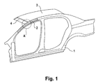
- FIG. 1 shows the lateral part of the body of a motor vehicle comprising an outer side wall 1, the inner A-pillar profile 2 and the roof 3.
- the inner A-pillar profile 2 is welded to the front roof frame 4 in the connection area A.
- Figure 2 shows a known, left-sided, inner A-pillar profile 2 in T-shape.
- FIG. 3 shows the left side, inner A-pillar profile 3 according to the present invention. It has a hat profile, so waives a projecting from the profile longitudinal leg.
- the abutment flange 6 is interrupted and has the inner part 2 of the A-pillar two retaining tabs 7, 7 '.
- the front roof frame profile 4 is inserted from above and comes to rest on the retaining tabs 7,7 '.
- Each of the two retaining tabs 7, 7 ' is then welded to the front roof frame profile 4. By the position of the retaining tabs a height fixation of the roof frame profile 4 is made.
- Fig. 4 shows the connection area A in an enlarged view.
- the retaining tabs 7 and 7 ' are welded at the welding points 12 and 12 with the front roof frame profile.
- the abutment flange 6 is interrupted in the connection area and is additionally lowered in relation to the profile longitudinal direction front and rear. In this recess region, it is thus formed as a retaining pocket 9 or 9 'and welded to the front roof frame profile 4 via the welding points 13 and 13'.
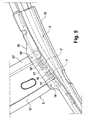
- Figure 5 is a plan view of the connection region corresponding to Figure 4.
- the additional retaining tabs increase the torsional rigidity and reduce the material thickness.
- the retaining tabs 7, 7 ' have, on the end facing away from the inner A-pillar profile part 2, a bevelled end 10, 10', which engages in corresponding through openings 11, 11 'of the front roof frame profile 4.
- the reinforcing plate 15 arranged in the A-pillar 15 can be seen.
- This reinforcing plate 15 no longer follows the profile longitudinal curvature in the connection region, but instead widens toward the roof frame profile 4.
- this tab-shaped widening region 16 of the reinforcing plate 15 extends less than 4 cm, preferably less than 3 cm inwards.
- the reinforcing plate 15 directly, ie in two sheet metal layers, with the abutment flanges 17 and 17 'of the front roof frame profile 4 via welds 14 and 14' are welded. Again, the torsional stiffness can be increased and the material thickness of the inner profile part 2 can be reduced.
Landscapes
- Engineering & Computer Science (AREA)
- Chemical & Material Sciences (AREA)
- Combustion & Propulsion (AREA)
- Transportation (AREA)
- Mechanical Engineering (AREA)
- Body Structure For Vehicles (AREA)
- Walking Sticks, Umbrellas, And Fans (AREA)
- Rod-Shaped Construction Members (AREA)
- Graft Or Block Polymers (AREA)
Applications Claiming Priority (1)
| Application Number | Priority Date | Filing Date | Title |
|---|---|---|---|
| DE102005044066A DE102005044066A1 (de) | 2005-09-15 | 2005-09-15 | Karosseriesäule |
Publications (2)
| Publication Number | Publication Date |
|---|---|
| EP1764286A1 true EP1764286A1 (fr) | 2007-03-21 |
| EP1764286B1 EP1764286B1 (fr) | 2009-11-18 |
Family
ID=37487739
Family Applications (1)
| Application Number | Title | Priority Date | Filing Date |
|---|---|---|---|
| EP06017415A Not-in-force EP1764286B1 (fr) | 2005-09-15 | 2006-08-22 | Montant de baie ou pilier de carrosserie de véhicule |
Country Status (3)
| Country | Link |
|---|---|
| EP (1) | EP1764286B1 (fr) |
| AT (1) | ATE448992T1 (fr) |
| DE (2) | DE102005044066A1 (fr) |
Cited By (1)
| Publication number | Priority date | Publication date | Assignee | Title |
|---|---|---|---|---|
| CN114007929A (zh) * | 2019-06-19 | 2022-02-01 | 标致雪铁龙汽车股份有限公司 | 具有在车顶横梁与车顶拱梁之间的加强零件的机动车辆结构件 |
Families Citing this family (2)
| Publication number | Priority date | Publication date | Assignee | Title |
|---|---|---|---|---|
| DE102008061490B3 (de) | 2008-12-10 | 2010-08-05 | Thyssenkrupp Drauz Nothelfer Gmbh | Karosserie für ein Kraftfahrzeug und Verfahren zur Herstellung einer Kraftfahrzeugkarosserie |
| JP6973264B2 (ja) * | 2018-04-20 | 2021-11-24 | トヨタ自動車株式会社 | ピラー構造 |
Citations (4)
| Publication number | Priority date | Publication date | Assignee | Title |
|---|---|---|---|---|
| JPH10218018A (ja) | 1997-02-10 | 1998-08-18 | Daihatsu Motor Co Ltd | 自動車の車体の上側部構造 |
| EP1127776A2 (fr) | 2000-02-26 | 2001-08-29 | Volkswagen Aktiengesellschaft | Agencement d'une structure porteuse d'une carrosserie d'un véhicule |
| DE10302463A1 (de) | 2003-01-23 | 2004-09-02 | Bayerische Motoren Werke Ag | Unlösbare Verbindung, insbesondere Eckverbindung, wenigstens zweier Längsteile einer Kraftfahrzeugkarosserie |
| WO2005021361A1 (fr) | 2003-08-27 | 2005-03-10 | Thyssenkrupp Steel Ag | Montant dans une structure porteuse de vehicule automobile de type 'space frame' |
-
2005
- 2005-09-15 DE DE102005044066A patent/DE102005044066A1/de not_active Withdrawn
-
2006
- 2006-08-22 AT AT06017415T patent/ATE448992T1/de active
- 2006-08-22 EP EP06017415A patent/EP1764286B1/fr not_active Not-in-force
- 2006-08-22 DE DE502006005388T patent/DE502006005388D1/de active Active
Patent Citations (4)
| Publication number | Priority date | Publication date | Assignee | Title |
|---|---|---|---|---|
| JPH10218018A (ja) | 1997-02-10 | 1998-08-18 | Daihatsu Motor Co Ltd | 自動車の車体の上側部構造 |
| EP1127776A2 (fr) | 2000-02-26 | 2001-08-29 | Volkswagen Aktiengesellschaft | Agencement d'une structure porteuse d'une carrosserie d'un véhicule |
| DE10302463A1 (de) | 2003-01-23 | 2004-09-02 | Bayerische Motoren Werke Ag | Unlösbare Verbindung, insbesondere Eckverbindung, wenigstens zweier Längsteile einer Kraftfahrzeugkarosserie |
| WO2005021361A1 (fr) | 2003-08-27 | 2005-03-10 | Thyssenkrupp Steel Ag | Montant dans une structure porteuse de vehicule automobile de type 'space frame' |
Cited By (1)
| Publication number | Priority date | Publication date | Assignee | Title |
|---|---|---|---|---|
| CN114007929A (zh) * | 2019-06-19 | 2022-02-01 | 标致雪铁龙汽车股份有限公司 | 具有在车顶横梁与车顶拱梁之间的加强零件的机动车辆结构件 |
Also Published As
| Publication number | Publication date |
|---|---|
| DE102005044066A1 (de) | 2007-04-05 |
| EP1764286B1 (fr) | 2009-11-18 |
| DE502006005388D1 (de) | 2009-12-31 |
| ATE448992T1 (de) | 2009-12-15 |
Similar Documents
| Publication | Publication Date | Title |
|---|---|---|
| DE102010036450B4 (de) | B-Säulenverstärkung eines Kraftfahrzeugs | |
| DE60221416T2 (de) | Modularer unterboden für ein kraftfahrzeug | |
| EP1118528B1 (fr) | Elément de carosserie comportant une tôle de renforcement | |
| EP3022086B1 (fr) | Structure de dossier de siège de véhicule et siège de véhicule | |
| DE102016223216A1 (de) | Karosserie-Bodenstruktur für ein Fahrzeug | |
| DE102009044417A1 (de) | Profil und Verfahren zu dessen Herstellung | |
| DE202014101186U1 (de) | Hydrogeformte Verstärkung vom Dachpaneel zu einer Seitensäule für Fahrzeuge | |
| EP1764286B1 (fr) | Montant de baie ou pilier de carrosserie de véhicule | |
| DE102005050617A1 (de) | Baugruppe für Fahrzeuge und ein Verfahren zum Herstellen derselben | |
| EP1055587B1 (fr) | Cloison pare-feu composée de plusieurs pièces pour carosserie de véhicule automobile | |
| DE102005011834B4 (de) | Seitlicher Dachrahmen für ein Kraftfahrzeug | |
| EP1172281A1 (fr) | Montant de porte, spécialement montant "A", pour une structure de carrosserie de véhicule et méthode de construction | |
| EP1863697B1 (fr) | Automobile munie d'une jupe laterale | |
| EP1764287B1 (fr) | Montant de carrosserie de véhicule, rail de toit et noeud d'assemblage à trois branches | |
| DE102010060702A1 (de) | A-Säule für eine Karosserie eines Kraftfahrzeuges | |
| DE102009007035A1 (de) | Bodenblech für ein Kraftfahrzeug und Verfahren zu seiner Herstellung | |
| DE102008054159A1 (de) | Verfahren zum Herstellen einer Klemmleiste | |
| DE102013002306A1 (de) | Fahrzeugsäule, insbesondere B-Säule eines Kraftfahrzeuges | |
| DE102016013301A1 (de) | Fahrzeugsäule für ein Kraftfahrzeug und Verfahren zum Herstellen einer Fahrzeugsäule für ein Kraftfahrzeug | |
| EP3450041B1 (fr) | Procédé de fabrication d'un corps creux tubulaire à partir d'une platine métallique découpée et partie de châssis ou de carrosserie pourvue du corps creux issu du procédé | |
| DE102004013511A1 (de) | Karosseriesäule | |
| DE102017201063B4 (de) | Karosserie-Bodenstruktur für ein zweispuriges Fahrzeug | |
| DE102021123788B4 (de) | Kraftfahrzeug-Biegeträger | |
| EP1127776A2 (fr) | Agencement d'une structure porteuse d'une carrosserie d'un véhicule | |
| DE102023124889B4 (de) | Bodenrahmen für eine Kraftfahrzeugkarosserie |
Legal Events
| Date | Code | Title | Description |
|---|---|---|---|
| PUAI | Public reference made under article 153(3) epc to a published international application that has entered the european phase |
Free format text: ORIGINAL CODE: 0009012 |
|
| AK | Designated contracting states |
Kind code of ref document: A1 Designated state(s): AT BE BG CH CY CZ DE DK EE ES FI FR GB GR HU IE IS IT LI LT LU LV MC NL PL PT RO SE SI SK TR |
|
| AX | Request for extension of the european patent |
Extension state: AL BA HR MK YU |
|
| 17P | Request for examination filed |
Effective date: 20070709 |
|
| 17Q | First examination report despatched |
Effective date: 20070813 |
|
| AKX | Designation fees paid |
Designated state(s): AT BE BG CH CY CZ DE DK EE ES FI FR GB GR HU IE IS IT LI LT LU LV MC NL PL PT RO SE SI SK TR |
|
| GRAP | Despatch of communication of intention to grant a patent |
Free format text: ORIGINAL CODE: EPIDOSNIGR1 |
|
| GRAS | Grant fee paid |
Free format text: ORIGINAL CODE: EPIDOSNIGR3 |
|
| GRAA | (expected) grant |
Free format text: ORIGINAL CODE: 0009210 |
|
| AK | Designated contracting states |
Kind code of ref document: B1 Designated state(s): AT BE BG CH CY CZ DE DK EE ES FI FR GB GR HU IE IS IT LI LT LU LV MC NL PL PT RO SE SI SK TR |
|
| REG | Reference to a national code |
Ref country code: GB Ref legal event code: FG4D Free format text: NOT ENGLISH |
|
| REG | Reference to a national code |
Ref country code: CH Ref legal event code: EP |
|
| REG | Reference to a national code |
Ref country code: IE Ref legal event code: FG4D |
|
| REF | Corresponds to: |
Ref document number: 502006005388 Country of ref document: DE Date of ref document: 20091231 Kind code of ref document: P |
|
| REG | Reference to a national code |
Ref country code: NL Ref legal event code: VDEP Effective date: 20091118 |
|
| LTIE | Lt: invalidation of european patent or patent extension |
Effective date: 20091118 |
|
| PG25 | Lapsed in a contracting state [announced via postgrant information from national office to epo] |
Ref country code: SE Free format text: LAPSE BECAUSE OF FAILURE TO SUBMIT A TRANSLATION OF THE DESCRIPTION OR TO PAY THE FEE WITHIN THE PRESCRIBED TIME-LIMIT Effective date: 20091118 Ref country code: PT Free format text: LAPSE BECAUSE OF FAILURE TO SUBMIT A TRANSLATION OF THE DESCRIPTION OR TO PAY THE FEE WITHIN THE PRESCRIBED TIME-LIMIT Effective date: 20100318 Ref country code: FI Free format text: LAPSE BECAUSE OF FAILURE TO SUBMIT A TRANSLATION OF THE DESCRIPTION OR TO PAY THE FEE WITHIN THE PRESCRIBED TIME-LIMIT Effective date: 20091118 Ref country code: IS Free format text: LAPSE BECAUSE OF FAILURE TO SUBMIT A TRANSLATION OF THE DESCRIPTION OR TO PAY THE FEE WITHIN THE PRESCRIBED TIME-LIMIT Effective date: 20100318 Ref country code: LT Free format text: LAPSE BECAUSE OF FAILURE TO SUBMIT A TRANSLATION OF THE DESCRIPTION OR TO PAY THE FEE WITHIN THE PRESCRIBED TIME-LIMIT Effective date: 20091118 Ref country code: ES Free format text: LAPSE BECAUSE OF FAILURE TO SUBMIT A TRANSLATION OF THE DESCRIPTION OR TO PAY THE FEE WITHIN THE PRESCRIBED TIME-LIMIT Effective date: 20100228 |
|
| PG25 | Lapsed in a contracting state [announced via postgrant information from national office to epo] |
Ref country code: PL Free format text: LAPSE BECAUSE OF FAILURE TO SUBMIT A TRANSLATION OF THE DESCRIPTION OR TO PAY THE FEE WITHIN THE PRESCRIBED TIME-LIMIT Effective date: 20091118 Ref country code: SI Free format text: LAPSE BECAUSE OF FAILURE TO SUBMIT A TRANSLATION OF THE DESCRIPTION OR TO PAY THE FEE WITHIN THE PRESCRIBED TIME-LIMIT Effective date: 20091118 Ref country code: LV Free format text: LAPSE BECAUSE OF FAILURE TO SUBMIT A TRANSLATION OF THE DESCRIPTION OR TO PAY THE FEE WITHIN THE PRESCRIBED TIME-LIMIT Effective date: 20091118 Ref country code: CY Free format text: LAPSE BECAUSE OF FAILURE TO SUBMIT A TRANSLATION OF THE DESCRIPTION OR TO PAY THE FEE WITHIN THE PRESCRIBED TIME-LIMIT Effective date: 20091118 |
|
| REG | Reference to a national code |
Ref country code: IE Ref legal event code: FD4D |
|
| PG25 | Lapsed in a contracting state [announced via postgrant information from national office to epo] |
Ref country code: RO Free format text: LAPSE BECAUSE OF FAILURE TO SUBMIT A TRANSLATION OF THE DESCRIPTION OR TO PAY THE FEE WITHIN THE PRESCRIBED TIME-LIMIT Effective date: 20091118 Ref country code: BG Free format text: LAPSE BECAUSE OF FAILURE TO SUBMIT A TRANSLATION OF THE DESCRIPTION OR TO PAY THE FEE WITHIN THE PRESCRIBED TIME-LIMIT Effective date: 20100218 Ref country code: DK Free format text: LAPSE BECAUSE OF FAILURE TO SUBMIT A TRANSLATION OF THE DESCRIPTION OR TO PAY THE FEE WITHIN THE PRESCRIBED TIME-LIMIT Effective date: 20091118 Ref country code: EE Free format text: LAPSE BECAUSE OF FAILURE TO SUBMIT A TRANSLATION OF THE DESCRIPTION OR TO PAY THE FEE WITHIN THE PRESCRIBED TIME-LIMIT Effective date: 20091118 Ref country code: NL Free format text: LAPSE BECAUSE OF FAILURE TO SUBMIT A TRANSLATION OF THE DESCRIPTION OR TO PAY THE FEE WITHIN THE PRESCRIBED TIME-LIMIT Effective date: 20091118 Ref country code: IE Free format text: LAPSE BECAUSE OF FAILURE TO SUBMIT A TRANSLATION OF THE DESCRIPTION OR TO PAY THE FEE WITHIN THE PRESCRIBED TIME-LIMIT Effective date: 20091118 |
|
| PG25 | Lapsed in a contracting state [announced via postgrant information from national office to epo] |
Ref country code: CZ Free format text: LAPSE BECAUSE OF FAILURE TO SUBMIT A TRANSLATION OF THE DESCRIPTION OR TO PAY THE FEE WITHIN THE PRESCRIBED TIME-LIMIT Effective date: 20091118 Ref country code: SK Free format text: LAPSE BECAUSE OF FAILURE TO SUBMIT A TRANSLATION OF THE DESCRIPTION OR TO PAY THE FEE WITHIN THE PRESCRIBED TIME-LIMIT Effective date: 20091118 |
|
| PLBE | No opposition filed within time limit |
Free format text: ORIGINAL CODE: 0009261 |
|
| STAA | Information on the status of an ep patent application or granted ep patent |
Free format text: STATUS: NO OPPOSITION FILED WITHIN TIME LIMIT |
|
| 26N | No opposition filed |
Effective date: 20100819 |
|
| PG25 | Lapsed in a contracting state [announced via postgrant information from national office to epo] |
Ref country code: GR Free format text: LAPSE BECAUSE OF FAILURE TO SUBMIT A TRANSLATION OF THE DESCRIPTION OR TO PAY THE FEE WITHIN THE PRESCRIBED TIME-LIMIT Effective date: 20100219 |
|
| BERE | Be: lapsed |
Owner name: GM GLOBAL TECHNOLOGY OPERATIONS, INC. Effective date: 20100831 |
|
| PG25 | Lapsed in a contracting state [announced via postgrant information from national office to epo] |
Ref country code: IT Free format text: LAPSE BECAUSE OF FAILURE TO SUBMIT A TRANSLATION OF THE DESCRIPTION OR TO PAY THE FEE WITHIN THE PRESCRIBED TIME-LIMIT Effective date: 20091118 Ref country code: MC Free format text: LAPSE BECAUSE OF NON-PAYMENT OF DUE FEES Effective date: 20100831 |
|
| REG | Reference to a national code |
Ref country code: CH Ref legal event code: PL |
|
| PG25 | Lapsed in a contracting state [announced via postgrant information from national office to epo] |
Ref country code: LI Free format text: LAPSE BECAUSE OF NON-PAYMENT OF DUE FEES Effective date: 20100831 Ref country code: CH Free format text: LAPSE BECAUSE OF NON-PAYMENT OF DUE FEES Effective date: 20100831 |
|
| REG | Reference to a national code |
Ref country code: DE Ref legal event code: R081 Ref document number: 502006005388 Country of ref document: DE Owner name: GM GLOBAL TECHNOLOGY OPERATIONS LLC (N. D. GES, US Free format text: FORMER OWNER: GM GLOBAL TECHNOLOGY OPERATIONS, INC., DETROIT, US Effective date: 20110323 |
|
| PG25 | Lapsed in a contracting state [announced via postgrant information from national office to epo] |
Ref country code: BE Free format text: LAPSE BECAUSE OF NON-PAYMENT OF DUE FEES Effective date: 20100831 |
|
| PG25 | Lapsed in a contracting state [announced via postgrant information from national office to epo] |
Ref country code: HU Free format text: LAPSE BECAUSE OF FAILURE TO SUBMIT A TRANSLATION OF THE DESCRIPTION OR TO PAY THE FEE WITHIN THE PRESCRIBED TIME-LIMIT Effective date: 20100519 Ref country code: LU Free format text: LAPSE BECAUSE OF NON-PAYMENT OF DUE FEES Effective date: 20100822 |
|
| PG25 | Lapsed in a contracting state [announced via postgrant information from national office to epo] |
Ref country code: TR Free format text: LAPSE BECAUSE OF FAILURE TO SUBMIT A TRANSLATION OF THE DESCRIPTION OR TO PAY THE FEE WITHIN THE PRESCRIBED TIME-LIMIT Effective date: 20091118 |
|
| REG | Reference to a national code |
Ref country code: AT Ref legal event code: MM01 Ref document number: 448992 Country of ref document: AT Kind code of ref document: T Effective date: 20110822 |
|
| PGFP | Annual fee paid to national office [announced via postgrant information from national office to epo] |
Ref country code: DE Payment date: 20120816 Year of fee payment: 7 |
|
| PG25 | Lapsed in a contracting state [announced via postgrant information from national office to epo] |
Ref country code: AT Free format text: LAPSE BECAUSE OF NON-PAYMENT OF DUE FEES Effective date: 20110822 |
|
| PG25 | Lapsed in a contracting state [announced via postgrant information from national office to epo] |
Ref country code: DE Free format text: LAPSE BECAUSE OF NON-PAYMENT OF DUE FEES Effective date: 20140301 |
|
| REG | Reference to a national code |
Ref country code: DE Ref legal event code: R119 Ref document number: 502006005388 Country of ref document: DE Effective date: 20140301 |
|
| REG | Reference to a national code |
Ref country code: FR Ref legal event code: PLFP Year of fee payment: 11 |
|
| PGFP | Annual fee paid to national office [announced via postgrant information from national office to epo] |
Ref country code: GB Payment date: 20160817 Year of fee payment: 11 |
|
| PGFP | Annual fee paid to national office [announced via postgrant information from national office to epo] |
Ref country code: FR Payment date: 20160712 Year of fee payment: 11 |
|
| GBPC | Gb: european patent ceased through non-payment of renewal fee |
Effective date: 20170822 |
|
| REG | Reference to a national code |
Ref country code: FR Ref legal event code: ST Effective date: 20180430 |
|
| PG25 | Lapsed in a contracting state [announced via postgrant information from national office to epo] |
Ref country code: GB Free format text: LAPSE BECAUSE OF NON-PAYMENT OF DUE FEES Effective date: 20170822 |
|
| PG25 | Lapsed in a contracting state [announced via postgrant information from national office to epo] |
Ref country code: FR Free format text: LAPSE BECAUSE OF NON-PAYMENT OF DUE FEES Effective date: 20170831 |