EP1764809B1 - Schutzelement für einen Kondensator mit Selbstheilungseigenschaften - Google Patents
Schutzelement für einen Kondensator mit Selbstheilungseigenschaften Download PDFInfo
- Publication number
- EP1764809B1 EP1764809B1 EP05108682.5A EP05108682A EP1764809B1 EP 1764809 B1 EP1764809 B1 EP 1764809B1 EP 05108682 A EP05108682 A EP 05108682A EP 1764809 B1 EP1764809 B1 EP 1764809B1
- Authority
- EP
- European Patent Office
- Prior art keywords
- membrane
- protection element
- temperature sensitive
- sensitive member
- current interruption
- Prior art date
- Legal status (The legal status is an assumption and is not a legal conclusion. Google has not performed a legal analysis and makes no representation as to the accuracy of the status listed.)
- Expired - Lifetime
Links
Images


Classifications
-
- H—ELECTRICITY
- H01—ELECTRIC ELEMENTS
- H01G—CAPACITORS; CAPACITORS, RECTIFIERS, DETECTORS, SWITCHING DEVICES, LIGHT-SENSITIVE OR TEMPERATURE-SENSITIVE DEVICES OF THE ELECTROLYTIC TYPE
- H01G2/00—Details of capacitors not covered by a single one of groups H01G4/00-H01G11/00
- H01G2/14—Protection against electric or thermal overload
Definitions
- the present invention relates to a protection element for a capacitor with self-healing properties, said protection element having a membrane and being provided for activating, upon a pressure exerted on said membrane, by a gas produced upon a self-healing operation occurred within said capacitor, a current interruption element to be connected in series with an electrode of said capacitor, said current interruption element being provided for interrupting an electrical current flowing towards said electrode when said pressure is exerted on said membrane, said current interruption element being operationally engaged with a temperature sensitive member provided to react when sensing a temperature increase above a predetermined value.
- Such a protection element is known from DE-B-1044947 .
- the known protection element protects the capacitor against overpressure and also acts as a thermal protection.
- the current interruption element comprises a wire extending between a spring and the membrane. When the pressure rises, the gas present in the housing of the protection element will exert a pressure on the membrane, thereby causing the latter to bulge. Since the wire is soldered to the membrane, the wire will follow the movement of the membrane. In case of overpressure, the force applied by the bulged membrane on the wire will be so high that the wire will break, thereby interrupting the current flowing through the wire.
- the thermal protection is realised by using a solder for the connection between the electrical conductor and the wire, which solder will start to melt if due to a too high electrical current the temperature has risen above the predetermined value. The melting of the solder will cause the wire to disconnect from the electrical conductor thereby also interrupting the current flow through the wire.
- Such a protection element is also known from EPS 0931324.
- the protection element described in the latter patent protects the self-healing capacitor against too high currents, which could occur during a self-healing operation.
- the current flowing through the failed spot in the capacitor could become high, which could on its turn lead to an evaporation of the electrode material and the formation of a gaseous plasma.
- the thus created gas forms then an overpressure leading to a bulge of the membrane.
- the pressure thus exerted on the membrane will activate the current interruption element, which on its turn will interrupt the current flowing to the electrode, thereby avoiding a further supply of electrical current to the capacitor and consequently the further evaporation of the electrode material.
- a problem of the protection element known from DE-B-1044947 is that it does not always work in a reliable manner. As a force is applied on the wire, which is connected to a spring, a strong force is required to overcome the elasticity of the wire and the spring, before the wire can be broken. As the wire is soldered to the membrane, care has to be taken to adequately solder the wire to the membrane. Indeed if the wire is not adequately soldered to the membrane the force applied on the wire by the membrane could cause a rupture of the soldering at a too early stage. Furthermore as a melt of the soldering is required to let the protection element operate as a thermal protection, care has to be taken that the wire is indeed disconnected from the membrane when the soldering melts and that it does not stick on the melt solder.
- FR-A-1214833 discloses a capacitor for an alternating current circuit.
- the capacitor is placed inside a box in an electrical circuit.
- the box also comprises a short-circuit contact that will shunt the capacitor if the walls of the box swell up. This avoids excess heating of the capacitor.
- the object of the invention is to realise a protection element for a capacitor with self-healing properties, which protects the capacitor against a too high temperature and an overpressure in a reliable manner.
- a protection element is characterised in that said membrane is provided to exert a pressure on said current interruption element in order to activate the latter, said temperature sensitive members being provided for applying a pressure on said current interruption element when sensing inside said capacitor said temperature increase above said predetermined value, in such a manner as to operate said current interruption element.
- the current interruption element always acts by exerting a pressure, independently whether it acts as a protection against overpressure or as a thermal protection.
- the current interruption element is submitted to a same movement, thereby offering a reliable protection element.
- a first preferred embodiment of a protection element according to the invention is characterised in that said temperature sensitive member comprises a spring made of a shape memory alloy, said spring being calibrated at said predetermined temperature value.
- the use of a spring made of a shape memory alloy enables a precise temperature calibration and thus a reliable operation of the protection element.
- the use of a shape memory alloy for a spring as part of an electronic component is known from JP-A-08 088142 .
- the current has to flow through the spring in order to operate the spring. In the present embodiment no current is flowing through the spring.
- a second preferred embodiment of a protection element according to the invention is characterised in that said membrane and said temperature sensitive member are made of a shape memory alloy and form a single component.
- the membrane has thus a double function leading to a reduction of components.
- a third preferred embodiment of a protection element according to the invention is characterised in that said temperature sensitive member comprises a wax actuator, calibrated at said predetermined temperature value. Once the predetermined temperature has been reached, the melted wax will occupy a larger volume than the solid wax, thereby operating the current interruption element.
- a fourth preferred embodiment of a protection element according to the invention is characterised in that said temperature sensitive member comprises a spring, embedded in a material, having a melting point corresponding to said predetermined temperature value. Once the material has melt, the embedded spring will be liberated and activate the current interruption element.
- a fifth preferred embodiment of a protection element according to the invention is characterised in that said current interruption element comprises an electrical conductor facing a cutting member provided to cut said conductor.
- the use of a cutting member enables a reliable and easy realisation of the current interruption element.
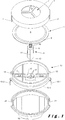
- the protection element according to the present invention and shown in figure 1 comprises a housing having an upper lid 1, provided with an opening 7. On the peripheral edge of the upper lid 1 flaps 2 and 3 are provided on opposite sides, which flaps extend in downward direction and beyond the peripheral edge.
- a membrane 4, made of flexible material, is dimensioned in such a manner as to fit inside the volume of the upper lid 1.
- the diameter of the membrane corresponds substantially to the inner diameter of the upper lid.
- the correspondence between those diameters avoids that gas would enter inside the housing of the protection element thereby disturbing its operation.
- the membrane has an inner part 6 surrounded by a border 5, which is thinner than the inner part. In mounted state of the protection element, the membrane faces the opening 7 so that a pressure can be applied on said membrane by a gas reaching said opening 7.
- the protection element further comprises a movably mounted element 8, which is part of a current interruption element.
- the element 8 is preferably substantially cylindrically shaped and provided with a knife shaped extremity (10), for example formed by two inclined end faces having a common edge. Guiding grooves 11 are preferably applied on the outer lateral sides of the element 8.
- the element 8 comprises a cavity 9 extending inside said element as from an upper face. The cavity is provided for lodging therein a temperature sensitive member 19 such as for example a spring, a bimetal or a wax actuator. Alternatively, the temperature sensitive member could be wrapped around the element 8 when formed by a spring, as illustrated in figure 4 . In the latter case there is no need for the element 8 to have guiding grooves 11 and a cavity 9.
- the protection element also comprises an electrical contact carrier part 12 provided with guiding protrusions 14 and 15 on its peripheral.
- the guiding protrusions co-operate with the flaps 2 and 3 of the upper lid, in such a manner that they can be engaged into the guiding protrusions, thereby fixing the upper lid on the contact carrier part.
- the guiding protrusions extend on lateral sides of an electrical conductor 13.
- the latter comprises two lateral wings 13-1 and 13-2 extending on opposite sides of the contact carrier part.
- the electrical conductor 13 further comprises a central part, extending between the lateral wings.
- the central part is formed by two horizontal wings 13-3 and 13-4 extending on both sides of an U-shaped part 13-5.
- the central part and the lateral wings form together a continuous electrical conductor, preferably made of copper, so that an electrical current applied on one of the lateral wings can flow via the central part to the other lateral wing.
- the U-shaped part 13-5 of the electrical conductor extends along an opening 16 crossing said electrical contact carrier part 12 in a vertical direction.
- the opening 16 there are provided further guiding protrusions 17, which co-operate with the guiding grooves 11 of the element 8 in such a manner as to guide a movement of said element 8 into said opening 16 and to avoid a rotation of the element 8 into the opening.
- the bottom of the U-shaped part 13-5 of the conductor 13 crosses the opening 16, the bottom of the U-shaped part forms as if to say the bottom of the opening 16.
- the element 8 is lodged inside the opening 16, the knife shaped extremity 10 of the element 8 faces the bottom of the U-shaped part 13-5 of the conductor. In such a manner, when a pressure is applied on the element 8, the knife shaped extremity 10 can cut the conductor 13, thereby acting as current interruption element.
- a knife shaped extremity 10 could be provided as cutting member.
- the element 8 could be made of glass provided with a sharp extremity 10.
- a switch instead of an U-shaped part and have the switch operated by the element 8.
- the electrical contact carrier part 12 is closed by a cover lid 18 having protrusions 20 and 21 fitting in said contact carrier part. In such a manner, the cover lid covers the conductor part 13 extending inside the contact carrier part 12.
- the element 8 can be operated by the membrane 4 as well as by the temperature sensitive member. Indeed, if a gas, for example formed inside the capacitor, following a self-healing operation, exerts a pressure on the membrane, this pressure will be exerted on the movable element 8. The pressure applied on the element 8 by the membrane 4, will move the element towards the conductor 13, thereby interrupting the current flowing through the conductor. If the temperature inside the capacitor increases, the temperature sensitive member 19 will react in applying a pressure on element 8, which will lead to the same effect as if the pressure was applied by the membrane 4.
- the temperature sensitive member 19 comprises a spring made of a shape memory alloy.
- the membrane 4 and the temperature sensitive member 19 could form a single element made of a shape memory alloy.
- shape memory alloy has the property that it takes a well-defined shape and applies a well-defined force when heated to a given or predetermined temperature.
- Figure 2 illustrates an example of the relationship between the force (F) applied by a shape memory alloy spring and the temperature (T). As illustrated in this figure 2 , below a temperature of 80°C the spring exerts nearly no force. In the range between 80° and 110° C, called the critical range, the force rapidly increases and thereafter remains stable at a temperature of more than 110°C.
- Figure 3 illustrates an example of the relationship between the force (F) applied by a shape memory alloy spring and its extension (curve 1). As illustrated in this figure 3 , once the value of 40 Newton has been reached an extension of the spring will lead to a reduction of the exerted force. Thus once the predetermined temperature at which the member 19 has to react has been established, an appropriate member capable to react on this predetermined temperature will be selected.
- the temperature sensitive member 19 is now formed by such a shape memory alloy spring placed in the cavity 9 or wrapped around the element 8, as shown in figure 2 , the spring will exert no force if the temperature remains beneath the predetermined temperature (see figure 2 ). So if the ambient temperature remains at normal operational conditions and if no or nearly no heat is produced inside the capacitor, the spring will remain passive and exert no force on the element 8. Once the temperature in or around the capacitor increases and reaches the critical range, the spring will leave its passive state and start to exert a force on the element 8.
- the spring, or membrane if the latter combines both functions, will now be chosen so that when the predetermined temperature has been reached, the latter is in its operational temperature range and able to exert its full force.
- the pressure applied on the element 8 will then be such as to activate element 8 and thus interrupt the current flowing through conductor 13. Therefore it is necessary to select an element 19, which is capable of exerting sufficient force on the element 8 in order to be able to cut the conductor 13. Since, as illustrated in figure 3 , the exerted force decreases by increased length of the spring, care has to be taken that the spring, even after having been extended, can still exert sufficient force in order to cut the conductor.
- curve 2 shows an example of the reaction characteristic of a copper conductor when a force is applied on it.
- the copper conductor needs a displacement of somewhat more than 2 mm before rupture. Consequently the spring or membrane will have to displace the conductor over a distance of somewhat more than 2 mm before a current interruption can occur.
- the membrane 4 is made of such a shape memory alloy, the increase of temperature will cause the membrane to bulge and thus also exert the necessary pressure on the element 8.
- shape memory alloy enables to choose a membrane applying the required pressure on the element 8 when the predetermined temperature has been reached in order to activate the current interruption element.
- the temperature sensitive member comprises a wax actuator, calibrated at the predetermined temperature.
- Figure 5 illustrates such a wax actuator at ambient temperature
- figure 6 illustrates the same wax actuator at said predetermined temperature.
- An actuator rod 27 is put into said wax.
- the actuator is mounted on element 8, in such a manner that the rod 27 enters into the cavity 9.
- the rod which is in the cavity 9, will then exert a pressure on the element.
- the stroke of the rod is dimensioned in such a manner that when the predetermined temperature has been reached, the rod exerts the necessary pressure on the element 8 to activate the current interruption element
- the wax could be adapted to present a melting temperature situated between 30° and 140° C.
- the melting curve could either show a sharp slope, such as illustrated in figure 7 , or a smooth slope, such as illustrated in figure 8 . Both figures 5 and 6 show the paraffin temperature versus its volumetric expansion.
- the element 8 could be formed by a cylindrical chamber filled with wax and closed by a piston. When the temperature reaches its predetermined valued, the wax will have expanded and will push on the piston so as to move the latter towards the knife.
- FIG. 8 Further embodiments could be formed by a spring embedded in a material, such as plastic, having a lower melting point than the material of which element 8 is made. When the material has melt due to a temperature increase, the spring will be liberated and act on the element 8.
- the temperature sensitive member and the membrane form together an inflatable membrane filled with a temperature sensitive fluid.
- the fluid When the temperature increases, the fluid will expand and inflate the membrane, thereby applying a pressure on element 8.
- the temperature sensitive member could comprise a bimetal or two contact elements connected to each other by means of a weld formed by a material, which melts at the predetermined temperature value. It could also be envisaged to use pyrotechnic gasses as temperature sensitive member.
Landscapes
- Engineering & Computer Science (AREA)
- Power Engineering (AREA)
- Microelectronics & Electronic Packaging (AREA)
- Fuses (AREA)
- Thermally Actuated Switches (AREA)
Claims (10)
- Schutzelement für einen Kondensator mit Selbstheilungseigenschaften, wobei das Schutzelement eine Membran (4) besitzt und vorgesehen ist zum Aktivieren, wenn auf die Membran (4) ein Druck ausgeübt wird, durch ein Gas, das bei einer innerhalb des Kondensators auftretenden Selbstheilungsoperation erzeugt wird, eines Stromunterbrechungselements (8) zum Geschaltetwerden in Reihe mit einer Elektrode des Kondensators, wobei das Stromunterbrechungselement (8) vorgesehen ist zum Unterbrechen eines zu der Elektrode (13-5) fließenden elektrischen Stroms, wenn der Druck auf die Membran (4) ausgeübt wird, wobei das Stromunterbrechungselement (8) operationeil mit einem temperaturempfindlichen Glied (19) in Eingriff steht, das vorgesehen ist, zu reagieren, wenn ein Temperaturanstieg über einen vorbestimmten Wert erfasst wird, dadurch gekennzeichnet, dass die Membran (4) vorgesehen ist, um einen Druck auf das Stromunterbrechungselement (8) auszuüben, um Letzteres zu aktivieren, wobei das temperaturempfindliche Glied (19) vorgesehen ist zum Anlegen eines Drucks an das Stromunterbrechungselement (8), wenn innerhalb des Kondensators der Temperaturanstieg über dem vorbestimmten Wert derart erfasst wird, dass das Stromunterbrechungselement (8) betätigt wird.
- Schutzelement nach Anspruch 1, dadurch gekennzeichnet, dass das temperaturempfindliche Glied (19) eine aus einer Formgedächtnislegierung hergestellte Feder umfasst, wobei die Feder auf den vorbestimmten Temperaturwert kalibriert ist.
- Schutzelement nach Anspruch 2, dadurch gekennzeichnet, dass die Feder um das Schneidglied (10) herum gewickelt ist.
- Schutzelement nach einem der Ansprüche 1 bis 3, dadurch gekennzeichnet, dass die Membran (4) und das temperaturempfindliche Glied (19) aus einer Formgedächtnislegierung hergestellt sind und eine einzelne Komponente bilden.
- Schutzelement nach Anspruch 1, dadurch gekennzeichnet, dass das temperaturempfindliche Glied (19) einen auf den vorbestimmten Temperaturwert kalibrierten Wachsaktuator umfasst.
- Schutzelement nach Anspruch 1, dadurch gekennzeichnet, dass das temperaturempfindliche Glied (19) eine Feder umfasst, die in ein Material mit einem Schmelzpunkt, der dem vorbestimmten Temperaturwert entspricht, eingebettet ist.
- Schutzelement nach Anspruch 1, dadurch gekennzeichnet, dass das temperaturempfindliche Glied (19) und die Membran (4) zusammen eine aufblasbare Membran bilden, die mit einem temperaturempfindlichen Fluid gefüllt ist, was vorgesehen ist, um die Membran beim Übersteigen des vorbestimmten Temperaturwerts aufzublasen.
- Schutzelement nach Anspruch 1, dadurch gekennzeichnet, dass das temperaturempfindliche Glied (19) ein auf dem vorbestimmten Temperaturwert kalibriertes Bimetall umfasst.
- Schutzelement nach Anspruch 1, dadurch gekennzeichnet, dass das temperaturempfindliche Glied (19) zwei Kontaktelemente umfasst, die miteinander mit Hilfe einer Schweißstelle verbunden sind, die durch ein Material ausgebildet ist, das bei dem vorbestimmten Temperaturwert schmilzt.
- Schutzelement nach einem der Ansprüche 1 bis 9, dadurch gekennzeichnet, dass das Stromunterbrechungselement (8) einen elektrischen Leiter (13) umfasst, der einem Schneidglied (10) zugewandt ist, das vorgesehen ist, um den Leiter (13) durchzuschneiden.
Priority Applications (4)
| Application Number | Priority Date | Filing Date | Title |
|---|---|---|---|
| EP05108682.5A EP1764809B1 (de) | 2005-09-20 | 2005-09-20 | Schutzelement für einen Kondensator mit Selbstheilungseigenschaften |
| ES05108682.5T ES2624533T3 (es) | 2005-09-20 | 2005-09-20 | Un elemento de protección para un condensador con propiedades auto-regeneradoras |
| CN2006101540553A CN1971782B (zh) | 2005-09-20 | 2006-09-20 | 用于具有自行回复性质的电容器的保护元件 |
| US11/523,804 US7436646B2 (en) | 2005-09-20 | 2006-09-20 | Protection element for a capacitor with self-healing properties |
Applications Claiming Priority (1)
| Application Number | Priority Date | Filing Date | Title |
|---|---|---|---|
| EP05108682.5A EP1764809B1 (de) | 2005-09-20 | 2005-09-20 | Schutzelement für einen Kondensator mit Selbstheilungseigenschaften |
Publications (2)
| Publication Number | Publication Date |
|---|---|
| EP1764809A1 EP1764809A1 (de) | 2007-03-21 |
| EP1764809B1 true EP1764809B1 (de) | 2017-03-01 |
Family
ID=35965925
Family Applications (1)
| Application Number | Title | Priority Date | Filing Date |
|---|---|---|---|
| EP05108682.5A Expired - Lifetime EP1764809B1 (de) | 2005-09-20 | 2005-09-20 | Schutzelement für einen Kondensator mit Selbstheilungseigenschaften |
Country Status (4)
| Country | Link |
|---|---|
| US (1) | US7436646B2 (de) |
| EP (1) | EP1764809B1 (de) |
| CN (1) | CN1971782B (de) |
| ES (1) | ES2624533T3 (de) |
Families Citing this family (15)
| Publication number | Priority date | Publication date | Assignee | Title |
|---|---|---|---|---|
| JP5896591B2 (ja) * | 2006-12-14 | 2016-03-30 | パーカー ハネフィン コーポレイションParker Hannifin Corporation | 容量性構造体、その製造方法およびその作動方法ならびに容量性構造体を備えたシステム |
| US7952261B2 (en) | 2007-06-29 | 2011-05-31 | Bayer Materialscience Ag | Electroactive polymer transducers for sensory feedback applications |
| EP2239793A1 (de) | 2009-04-11 | 2010-10-13 | Bayer MaterialScience AG | Elektrisch schaltbarer Polymerfilmaufbau und dessen Verwendung |
| US20110105004A1 (en) * | 2009-10-30 | 2011-05-05 | Gm Global Technology Operations, Inc. | Fan system for venting a vehicle |
| WO2011146052A1 (en) * | 2010-05-18 | 2011-11-24 | Empire Technology Development Llc | Ultracapacitors employing phase change materials |
| AT509919B1 (de) * | 2010-05-25 | 2012-09-15 | Piezocryst Advanced Sensorics | Thermoschutzelement für einen drucksensor |
| WO2012118916A2 (en) | 2011-03-01 | 2012-09-07 | Bayer Materialscience Ag | Automated manufacturing processes for producing deformable polymer devices and films |
| JP2014517331A (ja) | 2011-03-22 | 2014-07-17 | バイエル・インテレクチュアル・プロパティ・ゲゼルシャフト・ミット・ベシュレンクテル・ハフツング | 電場応答性高分子アクチュエータレンチキュラシステム |
| US9876160B2 (en) | 2012-03-21 | 2018-01-23 | Parker-Hannifin Corporation | Roll-to-roll manufacturing processes for producing self-healing electroactive polymer devices |
| KR20150031285A (ko) | 2012-06-18 | 2015-03-23 | 바이엘 인텔렉쳐 프로퍼티 게엠베하 | 연신 공정을 위한 연신 프레임 |
| US9590193B2 (en) | 2012-10-24 | 2017-03-07 | Parker-Hannifin Corporation | Polymer diode |
| CN105845446B (zh) * | 2016-05-13 | 2018-06-29 | 国网新疆电力公司乌鲁木齐供电公司 | 一种带有过压保护的石墨烯电容器 |
| DE212016000300U1 (de) * | 2016-12-21 | 2019-08-07 | Siemens Aktiengesellschaft | Kondensator mit integriertem Kurzschließer, insbesondere für zweipolige Sub-Module eines Mehrstufenumrichters, sowie einen mehrphasigen Mehrstufenumrichter mit einem solchen Kondensator |
| CN110411610B (zh) * | 2019-08-28 | 2024-03-19 | 广州计量检测技术研究院 | 体温计计量装置及其使用方法 |
| CN117238678B (zh) * | 2023-09-27 | 2024-05-17 | 烟台三水电器有限公司 | 一种过温自保护型超级电容器 |
Family Cites Families (12)
| Publication number | Priority date | Publication date | Assignee | Title |
|---|---|---|---|---|
| FR1214833A (fr) * | 1956-10-03 | 1960-04-12 | Bosch Gmbh Robert | Contacteur de court-circuit pour condensateurs séries |
| DE1044947B (de) | 1956-12-12 | 1958-11-27 | Standard Elektrik Lorenz Ag | Kombinierte Sicherung fuer elektrische Bauelemente |
| DE1764858A1 (de) * | 1968-08-20 | 1971-08-05 | Siemens Ag | Abschaltvorrichtung fuer einen in einem Gehaeuse eingebauten elektrischen Kondensator |
| DE2606176B2 (de) * | 1976-02-17 | 1978-05-11 | Tandard Elektrik Lorenz Ag, 7000 Stuttgart | Elektrischer Wickelkondensator mit Abschaltsicherung |
| DE3138271C2 (de) * | 1981-09-25 | 1985-01-17 | Ero-Starkstrom Kondensatoren Gmbh, 8300 Landshut | Kondensatoranordnung mit einer Vorrichtung zur Überwachung und Abschaltung eines elektrischen Kondensators |
| WO1987007780A1 (en) * | 1986-06-04 | 1987-12-17 | Aerovox Incorporated | Capacitor circuit interruption |
| US5148347A (en) * | 1990-05-09 | 1992-09-15 | Aerovox Incorporated | Polymer-encased electrical capacitor with pressure sensitive circuit interrupter |
| US5381301A (en) * | 1993-05-11 | 1995-01-10 | Aerovox Incorporated | Leak-tight and rupture proof, ultrasonically-welded, polymer-encased electrical capacitor with pressure sensitive circuit interrupter |
| JPH0888142A (ja) | 1994-09-16 | 1996-04-02 | Taiyo Yuden Co Ltd | 電子部品 |
| DE29624248U1 (de) * | 1996-06-21 | 2001-07-26 | EPCOS AG, 81541 München | Elektrischer Kondensator |
| CN2390269Y (zh) * | 1999-09-01 | 2000-08-02 | 苏州电力电容器厂 | 自保护式电容器 |
| CN2466785Y (zh) * | 2001-02-23 | 2001-12-19 | 冯申荣 | 电容器过压力保护装置 |
-
2005
- 2005-09-20 EP EP05108682.5A patent/EP1764809B1/de not_active Expired - Lifetime
- 2005-09-20 ES ES05108682.5T patent/ES2624533T3/es not_active Expired - Lifetime
-
2006
- 2006-09-20 US US11/523,804 patent/US7436646B2/en active Active
- 2006-09-20 CN CN2006101540553A patent/CN1971782B/zh active Active
Non-Patent Citations (1)
| Title |
|---|
| None * |
Also Published As
| Publication number | Publication date |
|---|---|
| CN1971782B (zh) | 2011-05-25 |
| US20070097594A1 (en) | 2007-05-03 |
| US7436646B2 (en) | 2008-10-14 |
| ES2624533T3 (es) | 2017-07-14 |
| EP1764809A1 (de) | 2007-03-21 |
| CN1971782A (zh) | 2007-05-30 |
Similar Documents
| Publication | Publication Date | Title |
|---|---|---|
| EP1764809B1 (de) | Schutzelement für einen Kondensator mit Selbstheilungseigenschaften | |
| KR101753635B1 (ko) | 감온 펠릿형 온도 퓨즈 | |
| EP0451678B1 (de) | Überlast-Schutzeinrichtung | |
| US20100073120A1 (en) | Thermal fuse for use in electric modules | |
| US20220246377A1 (en) | Electric circuit breaker | |
| US20040100351A1 (en) | Motor protector particularly useful with hermetic electromotive compressors | |
| KR100603222B1 (ko) | 모터 보호 장치 | |
| JPH07335103A (ja) | 二重安全サーモスタット | |
| KR20200106972A (ko) | 열 보호 기능을 갖는 온도 제어기 | |
| JPH02227928A (ja) | 熱応動スイッチ | |
| CN207690743U (zh) | 熔断器及具有其的电池包 | |
| CN102568955A (zh) | 形状记忆合金促动的断路器 | |
| EP2287876A1 (de) | Thermisch betätigter schalter | |
| JPS6026432Y2 (ja) | スイツチ装置 | |
| JPWO2014155679A1 (ja) | 熱応動開閉器、および、その製造方法 | |
| KR20160134492A (ko) | 일체형 복합 안전장치 | |
| US5235308A (en) | Thermal protector | |
| WO2019117153A1 (ja) | 感温ペレット型温度ヒューズ | |
| KR20090055844A (ko) | 도전성 패턴이 형성된 보호회로 기판을 포함하는 전지팩 | |
| CN1114782A (zh) | 热保护器 | |
| EP4533507A1 (de) | Überspannungsschutzvorrichtung mit verbessertem integriertem übertemperaturschutz | |
| JP2003338238A (ja) | 電動機保護装置 | |
| JP3247736U (ja) | 感温ペレット型温度ヒューズ | |
| JP4145732B2 (ja) | 感熱エレメント及びサーモプロテクタ並びに感熱スイッチ | |
| JPH0745171A (ja) | モータの過負荷保護装置 |
Legal Events
| Date | Code | Title | Description |
|---|---|---|---|
| PUAI | Public reference made under article 153(3) epc to a published international application that has entered the european phase |
Free format text: ORIGINAL CODE: 0009012 |
|
| AK | Designated contracting states |
Kind code of ref document: A1 Designated state(s): AT BE BG CH CY CZ DE DK EE ES FI FR GB GR HU IE IS IT LI LT LU LV MC NL PL PT RO SE SI SK TR |
|
| AX | Request for extension of the european patent |
Extension state: AL BA HR MK YU |
|
| 17P | Request for examination filed |
Effective date: 20070919 |
|
| AKX | Designation fees paid |
Designated state(s): AT BE BG CH CY CZ DE DK EE ES FI FR GB GR HU IE IS IT LI LT LU LV MC NL PL PT RO SE SI SK TR |
|
| 17Q | First examination report despatched |
Effective date: 20090126 |
|
| GRAP | Despatch of communication of intention to grant a patent |
Free format text: ORIGINAL CODE: EPIDOSNIGR1 |
|
| INTG | Intention to grant announced |
Effective date: 20161014 |
|
| RAP1 | Party data changed (applicant data changed or rights of an application transferred) |
Owner name: ABB SCHWEIZ AG |
|
| GRAS | Grant fee paid |
Free format text: ORIGINAL CODE: EPIDOSNIGR3 |
|
| GRAA | (expected) grant |
Free format text: ORIGINAL CODE: 0009210 |
|
| AK | Designated contracting states |
Kind code of ref document: B1 Designated state(s): AT BE BG CH CY CZ DE DK EE ES FI FR GB GR HU IE IS IT LI LT LU LV MC NL PL PT RO SE SI SK TR |
|
| REG | Reference to a national code |
Ref country code: GB Ref legal event code: FG4D |
|
| REG | Reference to a national code |
Ref country code: DE Ref legal event code: R081 Ref document number: 602005051394 Country of ref document: DE Owner name: HITACHI ENERGY SWITZERLAND AG, CH Free format text: FORMER OWNER: ABB TECHNOLOGY AG, ZUERICH, CH Ref country code: DE Ref legal event code: R081 Ref document number: 602005051394 Country of ref document: DE Owner name: ABB POWER GRIDS SWITZERLAND AG, CH Free format text: FORMER OWNER: ABB TECHNOLOGY AG, ZUERICH, CH |
|
| REG | Reference to a national code |
Ref country code: CH Ref legal event code: EP Ref country code: AT Ref legal event code: REF Ref document number: 872199 Country of ref document: AT Kind code of ref document: T Effective date: 20170315 |
|
| REG | Reference to a national code |
Ref country code: IE Ref legal event code: FG4D |
|
| REG | Reference to a national code |
Ref country code: DE Ref legal event code: R096 Ref document number: 602005051394 Country of ref document: DE |
|
| REG | Reference to a national code |
Ref country code: NL Ref legal event code: MP Effective date: 20170301 |
|
| REG | Reference to a national code |
Ref country code: LT Ref legal event code: MG4D |
|
| REG | Reference to a national code |
Ref country code: ES Ref legal event code: FG2A Ref document number: 2624533 Country of ref document: ES Kind code of ref document: T3 Effective date: 20170714 |
|
| REG | Reference to a national code |
Ref country code: AT Ref legal event code: MK05 Ref document number: 872199 Country of ref document: AT Kind code of ref document: T Effective date: 20170301 |
|
| PG25 | Lapsed in a contracting state [announced via postgrant information from national office to epo] |
Ref country code: LT Free format text: LAPSE BECAUSE OF FAILURE TO SUBMIT A TRANSLATION OF THE DESCRIPTION OR TO PAY THE FEE WITHIN THE PRESCRIBED TIME-LIMIT Effective date: 20170301 Ref country code: GR Free format text: LAPSE BECAUSE OF FAILURE TO SUBMIT A TRANSLATION OF THE DESCRIPTION OR TO PAY THE FEE WITHIN THE PRESCRIBED TIME-LIMIT Effective date: 20170602 |
|
| PG25 | Lapsed in a contracting state [announced via postgrant information from national office to epo] |
Ref country code: LV Free format text: LAPSE BECAUSE OF FAILURE TO SUBMIT A TRANSLATION OF THE DESCRIPTION OR TO PAY THE FEE WITHIN THE PRESCRIBED TIME-LIMIT Effective date: 20170301 Ref country code: AT Free format text: LAPSE BECAUSE OF FAILURE TO SUBMIT A TRANSLATION OF THE DESCRIPTION OR TO PAY THE FEE WITHIN THE PRESCRIBED TIME-LIMIT Effective date: 20170301 Ref country code: BG Free format text: LAPSE BECAUSE OF FAILURE TO SUBMIT A TRANSLATION OF THE DESCRIPTION OR TO PAY THE FEE WITHIN THE PRESCRIBED TIME-LIMIT Effective date: 20170601 Ref country code: SE Free format text: LAPSE BECAUSE OF FAILURE TO SUBMIT A TRANSLATION OF THE DESCRIPTION OR TO PAY THE FEE WITHIN THE PRESCRIBED TIME-LIMIT Effective date: 20170301 |
|
| REG | Reference to a national code |
Ref country code: FR Ref legal event code: PLFP Year of fee payment: 13 |
|
| PG25 | Lapsed in a contracting state [announced via postgrant information from national office to epo] |
Ref country code: NL Free format text: LAPSE BECAUSE OF FAILURE TO SUBMIT A TRANSLATION OF THE DESCRIPTION OR TO PAY THE FEE WITHIN THE PRESCRIBED TIME-LIMIT Effective date: 20170301 |
|
| PG25 | Lapsed in a contracting state [announced via postgrant information from national office to epo] |
Ref country code: SK Free format text: LAPSE BECAUSE OF FAILURE TO SUBMIT A TRANSLATION OF THE DESCRIPTION OR TO PAY THE FEE WITHIN THE PRESCRIBED TIME-LIMIT Effective date: 20170301 Ref country code: RO Free format text: LAPSE BECAUSE OF FAILURE TO SUBMIT A TRANSLATION OF THE DESCRIPTION OR TO PAY THE FEE WITHIN THE PRESCRIBED TIME-LIMIT Effective date: 20170301 Ref country code: EE Free format text: LAPSE BECAUSE OF FAILURE TO SUBMIT A TRANSLATION OF THE DESCRIPTION OR TO PAY THE FEE WITHIN THE PRESCRIBED TIME-LIMIT Effective date: 20170301 |
|
| PG25 | Lapsed in a contracting state [announced via postgrant information from national office to epo] |
Ref country code: PT Free format text: LAPSE BECAUSE OF FAILURE TO SUBMIT A TRANSLATION OF THE DESCRIPTION OR TO PAY THE FEE WITHIN THE PRESCRIBED TIME-LIMIT Effective date: 20170703 Ref country code: PL Free format text: LAPSE BECAUSE OF FAILURE TO SUBMIT A TRANSLATION OF THE DESCRIPTION OR TO PAY THE FEE WITHIN THE PRESCRIBED TIME-LIMIT Effective date: 20170301 Ref country code: IS Free format text: LAPSE BECAUSE OF FAILURE TO SUBMIT A TRANSLATION OF THE DESCRIPTION OR TO PAY THE FEE WITHIN THE PRESCRIBED TIME-LIMIT Effective date: 20170701 |
|
| REG | Reference to a national code |
Ref country code: DE Ref legal event code: R097 Ref document number: 602005051394 Country of ref document: DE |
|
| PLBE | No opposition filed within time limit |
Free format text: ORIGINAL CODE: 0009261 |
|
| STAA | Information on the status of an ep patent application or granted ep patent |
Free format text: STATUS: NO OPPOSITION FILED WITHIN TIME LIMIT |
|
| PG25 | Lapsed in a contracting state [announced via postgrant information from national office to epo] |
Ref country code: DK Free format text: LAPSE BECAUSE OF FAILURE TO SUBMIT A TRANSLATION OF THE DESCRIPTION OR TO PAY THE FEE WITHIN THE PRESCRIBED TIME-LIMIT Effective date: 20170301 |
|
| 26N | No opposition filed |
Effective date: 20171204 |
|
| PG25 | Lapsed in a contracting state [announced via postgrant information from national office to epo] |
Ref country code: SI Free format text: LAPSE BECAUSE OF FAILURE TO SUBMIT A TRANSLATION OF THE DESCRIPTION OR TO PAY THE FEE WITHIN THE PRESCRIBED TIME-LIMIT Effective date: 20170301 |
|
| REG | Reference to a national code |
Ref country code: CH Ref legal event code: PL |
|
| GBPC | Gb: european patent ceased through non-payment of renewal fee |
Effective date: 20170920 |
|
| PG25 | Lapsed in a contracting state [announced via postgrant information from national office to epo] |
Ref country code: MC Free format text: LAPSE BECAUSE OF FAILURE TO SUBMIT A TRANSLATION OF THE DESCRIPTION OR TO PAY THE FEE WITHIN THE PRESCRIBED TIME-LIMIT Effective date: 20170301 |
|
| REG | Reference to a national code |
Ref country code: IE Ref legal event code: MM4A |
|
| PG25 | Lapsed in a contracting state [announced via postgrant information from national office to epo] |
Ref country code: LU Free format text: LAPSE BECAUSE OF NON-PAYMENT OF DUE FEES Effective date: 20170920 |
|
| PG25 | Lapsed in a contracting state [announced via postgrant information from national office to epo] |
Ref country code: LI Free format text: LAPSE BECAUSE OF NON-PAYMENT OF DUE FEES Effective date: 20170930 Ref country code: CH Free format text: LAPSE BECAUSE OF NON-PAYMENT OF DUE FEES Effective date: 20170930 Ref country code: IE Free format text: LAPSE BECAUSE OF NON-PAYMENT OF DUE FEES Effective date: 20170920 Ref country code: GB Free format text: LAPSE BECAUSE OF NON-PAYMENT OF DUE FEES Effective date: 20170920 |
|
| REG | Reference to a national code |
Ref country code: FR Ref legal event code: PLFP Year of fee payment: 14 |
|
| PG25 | Lapsed in a contracting state [announced via postgrant information from national office to epo] |
Ref country code: HU Free format text: LAPSE BECAUSE OF FAILURE TO SUBMIT A TRANSLATION OF THE DESCRIPTION OR TO PAY THE FEE WITHIN THE PRESCRIBED TIME-LIMIT; INVALID AB INITIO Effective date: 20050920 |
|
| PG25 | Lapsed in a contracting state [announced via postgrant information from national office to epo] |
Ref country code: CY Free format text: LAPSE BECAUSE OF NON-PAYMENT OF DUE FEES Effective date: 20170301 |
|
| PG25 | Lapsed in a contracting state [announced via postgrant information from national office to epo] |
Ref country code: TR Free format text: LAPSE BECAUSE OF FAILURE TO SUBMIT A TRANSLATION OF THE DESCRIPTION OR TO PAY THE FEE WITHIN THE PRESCRIBED TIME-LIMIT Effective date: 20170301 |
|
| REG | Reference to a national code |
Ref country code: FI Ref legal event code: PCE Owner name: ABB POWER GRIDS SWITZERLAND AG |
|
| REG | Reference to a national code |
Ref country code: DE Ref legal event code: R081 Ref document number: 602005051394 Country of ref document: DE Owner name: HITACHI ENERGY SWITZERLAND AG, CH Free format text: FORMER OWNER: ABB SCHWEIZ AG, BADEN, CH Ref country code: DE Ref legal event code: R081 Ref document number: 602005051394 Country of ref document: DE Owner name: HITACHI ENERGY LTD, CH Free format text: FORMER OWNER: ABB SCHWEIZ AG, BADEN, CH Ref country code: DE Ref legal event code: R081 Ref document number: 602005051394 Country of ref document: DE Owner name: ABB POWER GRIDS SWITZERLAND AG, CH Free format text: FORMER OWNER: ABB SCHWEIZ AG, BADEN, CH |
|
| REG | Reference to a national code |
Ref country code: ES Ref legal event code: PC2A Owner name: ABB POWER GRIDS SWITZERLAND AG Effective date: 20210525 |
|
| REG | Reference to a national code |
Ref country code: FI Ref legal event code: PCE Owner name: HITACHI ENERGY SWITZERLAND AG |
|
| REG | Reference to a national code |
Ref country code: ES Ref legal event code: PC2A Owner name: HITACHI ENERGY SWITZERLAND AG Effective date: 20220526 |
|
| REG | Reference to a national code |
Ref country code: DE Ref legal event code: R081 Ref document number: 602005051394 Country of ref document: DE Owner name: HITACHI ENERGY SWITZERLAND AG, CH Free format text: FORMER OWNER: ABB POWER GRIDS SWITZERLAND AG, BADEN, CH Ref country code: DE Ref legal event code: R081 Ref document number: 602005051394 Country of ref document: DE Owner name: HITACHI ENERGY LTD, CH Free format text: FORMER OWNER: ABB POWER GRIDS SWITZERLAND AG, BADEN, CH |
|
| REG | Reference to a national code |
Ref country code: BE Ref legal event code: PD Owner name: ABB POWER GRIDS SWITZERLAND AG; CH Free format text: DETAILS ASSIGNMENT: CHANGE OF OWNER(S), ASSIGNMENT Effective date: 20220110 Ref country code: BE Ref legal event code: HC Owner name: HITACHI ENERGY SWITZERLAND AG; CH Free format text: DETAILS ASSIGNMENT: CHANGE OF OWNER(S), CHANGE OF OWNER(S) NAME Effective date: 20220128 |
|
| REG | Reference to a national code |
Ref country code: BE Ref legal event code: PD Owner name: ABB POWER GRIDS SWITZERLAND AG; CH Free format text: DETAILS ASSIGNMENT: CHANGE OF OWNER(S), ASSIGNMENT; FORMER OWNER NAME: ABB SCHWEIZ AG Effective date: 20230208 Ref country code: BE Ref legal event code: HC Owner name: HITACHI ENERGY SWITZERLAND AG; CH Free format text: DETAILS ASSIGNMENT: CHANGE OF OWNER(S), CHANGE OF OWNER(S) NAME; FORMER OWNER NAME: ABB POWER GRIDS SWITZERLAND AG Effective date: 20230208 |
|
| P01 | Opt-out of the competence of the unified patent court (upc) registered |
Effective date: 20230527 |
|
| REG | Reference to a national code |
Ref country code: BE Ref legal event code: PD Owner name: ABB POWER GRIDS SWITZERLAND AG; CH Free format text: DETAILS ASSIGNMENT: CHANGE OF OWNER(S), MERGE; FORMER OWNER NAME: ABB SCHWEIZ AG Effective date: 20240123 |
|
| REG | Reference to a national code |
Ref country code: DE Ref legal event code: R082 Ref document number: 602005051394 Country of ref document: DE Representative=s name: DENNEMEYER & ASSOCIATES RECHTSANWALTSGESELLSCH, DE Ref country code: DE Ref legal event code: R082 Ref document number: 602005051394 Country of ref document: DE Representative=s name: DENNEMEYER & ASSOCIATES S.A., DE Ref country code: DE Ref legal event code: R081 Ref document number: 602005051394 Country of ref document: DE Owner name: HITACHI ENERGY LTD, CH Free format text: FORMER OWNER: HITACHI ENERGY SWITZERLAND AG, BADEN, CH |
|
| REG | Reference to a national code |
Ref country code: FI Ref legal event code: PCE Owner name: HITACHI ENERGY LTD |
|
| REG | Reference to a national code |
Ref country code: ES Ref legal event code: PC2A Owner name: HITACHI ENERGY LTD Effective date: 20240925 |
|
| PGFP | Annual fee paid to national office [announced via postgrant information from national office to epo] |
Ref country code: FI Payment date: 20240918 Year of fee payment: 20 Ref country code: DE Payment date: 20240918 Year of fee payment: 20 |
|
| PGFP | Annual fee paid to national office [announced via postgrant information from national office to epo] |
Ref country code: BE Payment date: 20240918 Year of fee payment: 20 |
|
| PGFP | Annual fee paid to national office [announced via postgrant information from national office to epo] |
Ref country code: FR Payment date: 20240924 Year of fee payment: 20 |
|
| PGFP | Annual fee paid to national office [announced via postgrant information from national office to epo] |
Ref country code: CZ Payment date: 20240912 Year of fee payment: 20 |
|
| PGFP | Annual fee paid to national office [announced via postgrant information from national office to epo] |
Ref country code: IT Payment date: 20240924 Year of fee payment: 20 |
|
| PGFP | Annual fee paid to national office [announced via postgrant information from national office to epo] |
Ref country code: ES Payment date: 20241025 Year of fee payment: 20 |
|
| REG | Reference to a national code |
Ref country code: DE Ref legal event code: R082 Ref document number: 602005051394 Country of ref document: DE Representative=s name: DENNEMEYER & ASSOCIATES RECHTSANWALTSGESELLSCH, DE |
|
| REG | Reference to a national code |
Ref country code: DE Ref legal event code: R071 Ref document number: 602005051394 Country of ref document: DE |
|
| REG | Reference to a national code |
Ref country code: ES Ref legal event code: FD2A Effective date: 20250926 |
|
| PG25 | Lapsed in a contracting state [announced via postgrant information from national office to epo] |
Ref country code: ES Free format text: LAPSE BECAUSE OF EXPIRATION OF PROTECTION Effective date: 20250921 |
|
| PG25 | Lapsed in a contracting state [announced via postgrant information from national office to epo] |
Ref country code: CZ Free format text: LAPSE BECAUSE OF EXPIRATION OF PROTECTION Effective date: 20250920 |
|
| REG | Reference to a national code |
Ref country code: BE Ref legal event code: MK Effective date: 20250920 |