EP1765022B1 - Améliorations apportées à des systèmes de télécommunications ou s'y rapportant - Google Patents
Améliorations apportées à des systèmes de télécommunications ou s'y rapportant Download PDFInfo
- Publication number
- EP1765022B1 EP1765022B1 EP05447244A EP05447244A EP1765022B1 EP 1765022 B1 EP1765022 B1 EP 1765022B1 EP 05447244 A EP05447244 A EP 05447244A EP 05447244 A EP05447244 A EP 05447244A EP 1765022 B1 EP1765022 B1 EP 1765022B1
- Authority
- EP
- European Patent Office
- Prior art keywords
- connection
- transmission path
- path input
- cross
- output terminal
- Prior art date
- Legal status (The legal status is an assumption and is not a legal conclusion. Google has not performed a legal analysis and makes no representation as to the accuracy of the status listed.)
- Expired - Lifetime
Links
Images





Classifications
-
- H—ELECTRICITY
- H04—ELECTRIC COMMUNICATION TECHNIQUE
- H04Q—SELECTING
- H04Q3/00—Selecting arrangements
- H04Q3/64—Distributing or queueing
- H04Q3/68—Grouping or interlacing selector groups or stages
-
- H—ELECTRICITY
- H04—ELECTRIC COMMUNICATION TECHNIQUE
- H04Q—SELECTING
- H04Q3/00—Selecting arrangements
- H04Q3/0004—Selecting arrangements using crossbar selectors in the switching stages
-
- H—ELECTRICITY
- H04—ELECTRIC COMMUNICATION TECHNIQUE
- H04Q—SELECTING
- H04Q2213/00—Indexing scheme relating to selecting arrangements in general and for multiplex systems
- H04Q2213/1302—Relay switches
-
- H—ELECTRICITY
- H04—ELECTRIC COMMUNICATION TECHNIQUE
- H04Q—SELECTING
- H04Q2213/00—Indexing scheme relating to selecting arrangements in general and for multiplex systems
- H04Q2213/1304—Coordinate switches, crossbar, 4/2 with relays, coupling field
-
- H—ELECTRICITY
- H04—ELECTRIC COMMUNICATION TECHNIQUE
- H04Q—SELECTING
- H04Q2213/00—Indexing scheme relating to selecting arrangements in general and for multiplex systems
- H04Q2213/13076—Distributing frame, MDF, cross-connect switch
-
- H—ELECTRICITY
- H04—ELECTRIC COMMUNICATION TECHNIQUE
- H04Q—SELECTING
- H04Q2213/00—Indexing scheme relating to selecting arrangements in general and for multiplex systems
- H04Q2213/13092—Scanning of subscriber lines, monitoring
-
- H—ELECTRICITY
- H04—ELECTRIC COMMUNICATION TECHNIQUE
- H04Q—SELECTING
- H04Q2213/00—Indexing scheme relating to selecting arrangements in general and for multiplex systems
- H04Q2213/13109—Initializing, personal profile
-
- H—ELECTRICITY
- H04—ELECTRIC COMMUNICATION TECHNIQUE
- H04Q—SELECTING
- H04Q2213/00—Indexing scheme relating to selecting arrangements in general and for multiplex systems
- H04Q2213/13141—Hunting for free outlet, circuit or channel
-
- H—ELECTRICITY
- H04—ELECTRIC COMMUNICATION TECHNIQUE
- H04Q—SELECTING
- H04Q2213/00—Indexing scheme relating to selecting arrangements in general and for multiplex systems
- H04Q2213/13146—Rerouting upon blocking/overload, rearrangement
-
- H—ELECTRICITY
- H04—ELECTRIC COMMUNICATION TECHNIQUE
- H04Q—SELECTING
- H04Q2213/00—Indexing scheme relating to selecting arrangements in general and for multiplex systems
- H04Q2213/13166—Fault prevention
-
- H—ELECTRICITY
- H04—ELECTRIC COMMUNICATION TECHNIQUE
- H04Q—SELECTING
- H04Q2213/00—Indexing scheme relating to selecting arrangements in general and for multiplex systems
- H04Q2213/13173—Busy signals
-
- H—ELECTRICITY
- H04—ELECTRIC COMMUNICATION TECHNIQUE
- H04Q—SELECTING
- H04Q2213/00—Indexing scheme relating to selecting arrangements in general and for multiplex systems
- H04Q2213/1334—Configuration within the switch
Definitions
- the present invention relates to a method and apparatus for rearranging connections between a multitude of transmission lines for providing telecommunications services especially to the provision of a permanent new service such as xDSL.
- Preferred embodiments relate to a method and apparatus for rearranging connections between a first and a second set of lines, e.g. subscriber and service transmission lines.
- MDF main distribution frame
- An MDF is a cross-connection frame where incoming cables terminate and can be cross-connected manually to central office telecommunications equipment.
- An MDF may be placed together with the local exchange, or for instance, in a remote subscriber access node.
- EP 1549102 describes a method and apparatus for a non-blocking multistage optical switch using crosspoint switches for performing group switching in DWDM optical networks.
- the group connector comprises a first stage comprising r n x m crossbar switch modules, wherein m is greater than or equall to n-1; a second stage comprising m r x r crossbar switch modules; and a third stage comprising r M x N concentrator switch modules.
- the switches used are any-to-any switches requiring a very large number of individual switches.
- the present invention also provides a cross-connect device having a plurality of N first transmission path input/output terminals and a plurality of M second transmission path input/output terminals, the device having a remotely actuated cross-connection arrangement comprising:
- At least a fourth sparse cross-bar arrangement can also be provided having seventh connection lines connected to at least some of the sixth connection lines, and eighth connection lines and a plurality of fourth switch elements for connecting selective ones of the seventh connection lines to selective ones of the eighth connection lines, the eighth connection lines being connected to at least some of the second connection lines, whereby the total number of switching elements of the first to fourth sparse cross-bar is less than N x M.
- the addition of a fourth sparse cross-bar provides additional switching possibilities which helps to obtain a non-blocking cross-connect.
- S can be less than N and for the first connection lines which are not connected to the second sparse cross-bar arrangement, connections to the second transmission path input/output terminals is only possible using the first switching elements. This has the advantage that for a certain number of inputs, there is already a possible output and the number of switches in the first stage is lower.
- the third and fourth sparse cross-bar arrangements are adapted so that a fourth connection line from the first set can be connected to a third set of the second transmission path input/output terminals and a fourth connection line from the second set can be connected to a fourth set of the second transmission path input/output terminals. Again this improves the possibility of obtaining a connection between the inputs and outputs.
- the device is adapted to implement a non-blocking rerouting by an automatic process. This allows remote switching and deblocking.
- the non-blocking rerouting can be by rearrangement. By allowing rearrangement of which switches are activated, the opportunities to make a through connection are increased.
- the rearrangement can be a chain of rearrangements. For instance multiple switches may be deactivated/activated in order to rearrange the switching matrix.
- the device may be arranged to bridge the connection between a subscriber terminal and a telecommunications service.
- one or more of the first transmission path input/output terminals can be arranged to provide connection to subscriber transmission lines and the one or more of the second transmission path input/output terminals can be arranged to provide connection for service transmission lines.
- the present invention provides a method of adapting in situ a telecommunications network apparatus, the apparatus having a plurality of N first transmission path input/output terminals and a plurality of M second transmission path input/output terminals, and a remotely actuated cross-connection arrangement comprising:
- a further rerouting step can be determining if there is an idle second transmission path input/output terminal and if so, determining if this idle second transmission path input/output terminal can be connected to a busy first transmission path input/output terminal through a third connection path, and if so rearranging the busy first transmission path input/output terminal to be connected to the idle second transmission path input/output terminal via the third connection path followed by activating selective ones of the first to at least third switching elements to provide the first or second connection path between a first transmission path input/output terminal and a second transmission path input/output terminal.
- a further rerouting step can be selecting a busy a first transmission path input/output terminal and de-selecting the first switching element which provides the connection of the busy first terminal to a second transmission path input/output terminal, and activating second and at least third switching elements to provide the connection path between the busy first transmission path input/output terminal and a second transmission path input/output
- Providing the first or second connection includes a chain of rearrangements in which more than one rearrangement of the activation of switching elements is carried out in the second sparse cross-bar.
- the device may be adapted to be used in a wired telecommunications system.
- the network apparatus may be adapted to be used in a wireless or optical telecommunications system.
- one, more or all of the first and second inputs/outputs (N, M) may be adapted for conductive transmission path technology.
- One, more, or all first and second inputs/outputs (N, M) may be adapted for optical transmission path technology.
- One, more or all the connection paths may be conductive transmission paths.
- One, more or all connection paths may be optical transmission paths.
- connection options i.e. three or more interlinked sparse cross-bars
- the cross connection device is comprised in a switch card arranged to be connectable to one or more switch cards.
- the cross connection device is comprised in a switch card arranged to be connectable to one or more subscriber transmission lines.
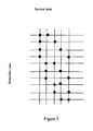
- FIG. 2 shows a cross connection arrangement in which each subscriber line has four different connection paths (S1-D1, S1-D2... S1-D8, S2-D1 S2-D3 ??S2-D8) to connect with four of the eight DSLAM port lines.
- Some of the DSLAM port lines are connected to only one of the two shown subscriber lines e.g. D2, D3, D4.
- Other DSLAM port lines are connected to both of the two subscriber lines D1, D8.
- the arrangement provides a 4x expansion for each subscriber line.
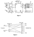
- FIGS 3a and 3b show two alternative possible implementations of the present invention using relay contact switches which can be used at the crosspoints of the embodiments of the present invention.
- switches could be used in any embodiment, e.g. electromechanical or semiconductor switches.
- Latching relays are preferably used in order to preserve the switching state when power is removed. Switching of the relays will be under the control of a controller, e.g. microcontroller which may be onboard or remote. In order to save power, relay operations will be done sequentially, i.e. power will only ever be applied to one relay at a time. Switching an individual relay takes of the order of 5ms, so an entire relay of 100 relays can be refreshed in less than 1s.
- Figures 3a and 3b show two possible arrangements for an expansion of four for a single subscriber line with four DSLAM lines.
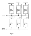
- Figure 5 A similar illustration to Figure 4 is shown in Figure 5 , also with an expansion factor of two. In this example however, there are ten subscriber lines and five service ports.
- Service Port Blocking all service ports are used, and no further service can be granted.
- the only de-blocking option here is to install more service ports, together with another matrix to connect the subscribers to them.
- the present invention has as an object to delay this moment as long as possible.
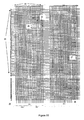
- Figures 6 and 7 shows examples of systems and communications architectures which can be used to implement the present invention.
- Figure 6 shows a switch matrix of two rows of switch modules 100-102, 200-202. The dashed lines indicate that the matrix can be expanded in the horizontal and/or vertical direction.
- Fifty subscriber lines are each connected to POTS disconnect switches 100, 200. These switches 100, 200 are provided to allow each subscriber to be connected to its respective default POTS port. A relay contact (not shown) on the switches 100, 200 for each subscriber line is provided to connect each line through to its default POTS connection.
- Each switch 100, 200 is respectively connected to corresponding cross connection switch cards 101, 102, 201, 202.
- Switch cards 101, 102 provide connection for subscriber lines 1-50 and switch cards 201, 202 provide connection for subscriber lines 51-100.
- Cross connection switch cards 101, 201, and 102, 202 are respectively connected to DSLAM transmission lines 1-24 and 25-48.
- switches 100 and 101 Fifty subscribers would be connected to twenty-four DSLAM ports. On the addition of switch 102, fifty subscribers could be connected to forty-eight DSLAM ports. On the addition of the bottom row, one hundred subscribers could be connected to forty-eight DSLAM ports.
- FIG. 7 shows a proposed communications architecture in which the switch cards are connected together by means of a serial bus (e.g. RS485), under the control of a master controller card 300.
- This master control card 300 controls the configuration of each of the switches, and the switch cards determine their address, and hence their position in the matrix, from pins on the backplane connector (provides connectivity between individual elements of the system) into which they are plugged.
- a cross-connect arrangement or a concentrator connects specific, idle inputs/outputs to arbitrary, idle inputs/outputs.
- concentrators where one number of inputs/outputs N is greater than the other number of inputs/outputs M are mainly of interest.
- the topology of the switching matrix is irregular.
- a switching matrix is said to be irregular if input-output connections can have different delays, where delay is defined as the number of switching elements through which the signal must pass.
- delay is defined as the number of switching elements through which the signal must pass.
- the present invention concerns an irregular R-stage switching matrix with R equal to or greater than 3 and will be described for example only with respect to 3 and 4 stage switching matrices.
- the cross-connect arrangements according to the present invention having N first inputs/outputs that are to be connected to any of M second input/outputs, and the total number of switches is less than N x M.
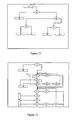
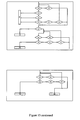
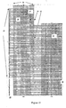
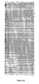
- Fig. 8 shows a 4-stage switching matrix in accordance with an embodiment of the present invention with stages 26-29.
- the matrix comprises on the left hand side of the figure N horizontal conductive lines terminated by first inputs/outputs and M vertical conductive lines terminated by second inputs/outputs. Reference to horizontal and vertical lines applies only to the figure - it is not intended that the words horizontal or vertical refer to the physical arrangement of the lines.
- switching elements are provided in accordance with a particular scheme.
- the subscriber inputs 20 are shown on the left and the service outputs 22 (e.g. xDSL) are shown on the left at the top.
- the crosspoints 24 of the first stage 26 are switching elements through which the outputs are directly reachable from the inputs.
- all inputs 20 of the first stage 26 have at least the same number "a" of crosspoints or switches 24.
- Some of the lines in Fig. 8 have 2 switches.
- Other lines have 3, e.g. input lines 65-96.
- the present invention is not limited to a constant number of switches per line and can be extended to a variable number of switches at crosspoints.
- the present invention also includes a first block of inputs 20 connected by horizontal lines to a first number of switches at crosspoints, e.g. 1 switch at a crosspoint per input and a second block has a second number of switches at crosspoints, e.g. more than 1 switch at a crosspoint per input as shown schematically in Fig. 9 .
- the ordering of the crosspoints in the second block of the first stage is not at random, but avoids repeating combinations in order to increase the connectivity of the switching matrix.
- a topology having a first stage comprising a first block 30 with 1 switch at a crosspoint per input 20 and second block 32 with 2 switches at crosspoints per input 20 as shown in Fig. 9 .
- inputs 20 belonging to the first block 30 are said to be class 1 inputs; inputs belonging to the second block 32 are said to be class 2 inputs.
- the 2 nd , 3 rd and 4 th stages 27-29 of the switching matrix are a means of connecting an arbitrary input of the first stage 26 to one of a part of the set of outputs 22 or the entire set of outputs 22.
- the second stage 27 has always one or more switches at crosspoints 25 on a first set of lines, e.g. the odd lines, and one or more switches at a crosspoints on a second set of lines, e.g. even lines, whereby the first and second set do not overlap.
- a first set e.g. the first half of the outputs 22 is reachable through the third and fourth stages 28 and 29.
- a second set e.g. the second half, of the outputs 22 is reachable through the third and fourth stages 28 and 29 (see Fig. 10 ).
- the outputs 22 are reachable through the first stage 26 directly for some of the inputs 20 and also outputs 22 are reachable from the fourth stage 29 via the second and third stages 27, 28.
- the inputs 20 have access to the outputs 22.
- a controlling means which may be located anywhere, e.g. with the cross-connect or somewhere else in the telecommunications network, i.e. remote controlling means, first checks the possibility to route the specified input 20 to an output 22 directly through the first stage 26.
- the controlling means tries first of all to find a way through the second to fourth stages 27-29 to reach an idle output 22. If this is not possible, the controlling means can attempt a rearrangement of the matrix, i.e. try to reroute the connection paths by altering the switches along those paths.
- a routing policy in accordance with an embodiment of the present invention will be described with reference to the embodiments described with reference to figures 8 to 11 .
- the present invention is not limited to four stage switching matrices and can be applied to any R-stage matrices where R is equal to or greater than 3.
- the controlling means can be implemented by software running on a suitable computing device, e.g. a personal computer or a workstation.
- the software is provided with code for detecting connection requests. Furthermore the software runs initially on an internal database. When a solution is found, the physical connection is performed. This approach makes a make-before-break strategy possible. This means that whenever a rearrangement of an existing connection should be performed, first a parallel connection is made before breaking the original one.
- an input for which the connection request arrives is designated as input A.
- the controlling means starts the search for an output to which the specific input can be connected.
- the routing policy comprises the following steps:
- a set of 25 inputs is selected none of which can be connected to 7 of the 25 outputs. If a connection request arrives for this set of inputs, independent of the order, at least 7 inputs will be blocked for this concentrator, no matter how intelligent the control algorithm. Another property is that the blocking can possibly occur before a reasonable number of connection requests has been made, e.g. before the 19 th connection request. The appearance of blocking in a little employed switching matrix is unacceptable. In the following simulation results will be discussed, proving the quasi-non-blocking property of the current invention.
- the present invention also includes a telecommunications network apparatus as hereinbefore described with reference to Figures 2 to 15 or a telecommunications network system as hereinbefore described with reference to Figures 2 to 15 .
- the present invention also includes a method of adapting an in situ telecommunications network apparatus as hereinbefore described with reference to Figures 2 to 15 .
- Stubs cause a degradation in frequency performance of the circuit and, in fact, the number and characteristics of the stubs attached to a particular live circuit varies as other subscribers are connected or disconnected, and this change in electrical characteristic can be enough for the line to drop out of service. Accordingly, a design that reduces the number or size of stubs is a significant benefit.
- the second to at least third stages of the cross-connect device according to the present invention as well as the controller may be supplied as separate modules which may be used to upgrade an existing installation.
Landscapes
- Engineering & Computer Science (AREA)
- Computer Networks & Wireless Communication (AREA)
- Data Exchanges In Wide-Area Networks (AREA)
- Use Of Switch Circuits For Exchanges And Methods Of Control Of Multiplex Exchanges (AREA)
Claims (23)
- Dispositif d'interconnexion comportant une pluralité de N premières bornes d'entrée/sortie de trajet de transmission (20) et une pluralité de M deuxièmes bornes d'entrée/sortie de trajet de transmission (22), le dispositif comportant un agencement d'interconnexion actionné à distance caractérisé par :un premier agencement de barres croisées clairsemé (26) ayant des premières lignes de connexion connectées à la pluralité de premières bornes d'entrée/sortie de trajet de transmission (20) et des deuxièmes lignes de connexion connectées à la pluralité de deuxièmes bornes d'entrée/sortie de trajet de transmission (22) et une pluralité de premiers éléments de commutation (24) pour connecter des lignes sélectives parmi les premières lignes de connexion à des lignes sélectives parmi les deuxièmes lignes de connexion,un deuxième agencement de barres croisées clairsemé (27) ayant des troisièmes lignes de connexion connectées à au moins certaines des premières lignes de connexion, et des quatrièmes lignes de connexion et une pluralité de deuxièmes éléments de commutation (25) pour connecter des lignes sélectives parmi les troisièmes lignes de connexion à des lignes sélectives parmi les quatrièmes lignes de connexion, etau moins un troisième agencement de barres croisées clairsemé (28) ayant des cinquièmes lignes de connexion connectées à au moins certaines des quatrièmes lignes de connexion, et des sixièmes lignes de connexion et une pluralité de troisièmes éléments de commutation pour connecter des lignes sélectives parmi les cinquièmes lignes de connexion à des lignes sélectives parmi les sixièmes lignes de connexion, le dispositif ayant des trajets de connexion pouvant être sélectionnés entre les sixièmes lignes de connexion et au moins certaines des deuxièmes bornes d'entrée/sortie de trajet de transmission (22), par le biais duquel le nombre total d'éléments de commutation pour lesdits au moins premier à troisième agencements de barres croisées clairsemés est inférieur à N x M.
- Dispositif d'interconnexion selon la revendication 1, caractérisé en outre par au moins un quatrième agencement de barres croisées clairsemé (29) ayant des septièmes lignes de connexion connectées à au moins certaines des sixièmes lignes de connexion, et des huitièmes lignes de connexion et une pluralité de quatrièmes éléments de commutation pour connecter des lignes sélectives parmi les septièmes lignes de connexion à des lignes sélectives parmi les huitièmes lignes de connexion, les huitièmes lignes de connexion étant connectées à au moins certaines des deuxièmes lignes de connexion, par le biais duquel le nombre total d'éléments de commutation des premier à quatrième agencements de barres croisées clairsemés est inférieur à N x M.
- Dispositif d'interconnexion selon la revendication 1 ou 2, caractérisé en ce que le nombre total d'éléments de commutation est inférieur à 50 %, inférieur à 40 %, inférieur à 30 %, ou inférieur à 20 % de NxM.
- Dispositif d'interconnexion selon l'une quelconque des revendications précédentes, caractérisé en ce qu'il y a S troisièmes lignes et T quatrièmes lignes, U cinquièmes lignes et V sixièmes lignes et les relations entre N, M, S, T, U et V sont :S est inférieur ou égal à N,T est inférieur ou égal à S,U ou V est inférieur ou égal à T.
- Dispositif d'interconnexion selon la revendication 5, caractérisé en ce qu'il y a W septièmes lignes et X huitièmes lignes, et W et X sont inférieurs ou égaux à T.
- Dispositif d'interconnexion selon la revendication 4 ou 5, caractérisé en ce que S est inférieur à N et, pour les premières lignes de connexion qui ne sont pas connectées au deuxième agencement de barres croisées clairsemé (27), des connexions aux deuxièmes bornes d'entrée/sortie de trajet de transmission (22) ne sont possibles qu'en utilisant les premiers éléments de commutation (24).
- Dispositif d'interconnexion selon l'une quelconque des revendications précédentes, caractérisé en ce que le deuxième agencement de barres croisées clairsemé (27) a des premier et deuxième ensembles non superposés de quatrièmes lignes de connexion et chaque troisième ligne de connexion peut être connectée à une quatrième ligne de connexion soit dans le premier, soit dans le deuxième ensemble par les deuxièmes éléments de commutation (25).
- Dispositif d'interconnexion selon la revendication 7, caractérisé en ce que les troisième et quatrième agencements de barres croisées clairsemés (28, 29), s'ils sont présents, sont adaptés de sorte qu'une quatrième ligne de connexion du premier ensemble puisse être connectée à un troisième ensemble des deuxièmes bornes d'entrée/sortie de trajet de transmission (22) et qu'une quatrième ligne de connexion du deuxième ensemble puisse être connectée à un quatrième ensemble des deuxièmes bornes d'entrée/sortie de trajet de transmission (22).
- Dispositif d'interconnexion selon l'une quelconque des revendications précédentes, caractérisé en ce que le dispositif est adapté pour effectuer un réacheminement non bloquant par un processus automatique.
- Dispositif d'interconnexion selon la revendication 9, caractérisé en ce que le réacheminement non bloquant est effectué par réagencement.
- Dispositif d'interconnexion selon la revendication 10, caractérisé en ce que le réagencement est une chaîne de réagencements.
- Dispositif d'interconnexion selon l'une quelconque des revendications précédentes agencé pour ponter la connexion entre un terminal d'abonné et un service de télécommunication.
- Dispositif d'interconnexion selon l'une quelconque des revendications précédentes, caractérisé en ce qu'une ou plusieurs des premières bornes d'entrée/sortie de trajet de transmission (20) sont agencées pour fournir une connexion à des lignes de transmission d'abonnés.
- Dispositif d'interconnexion selon l'une quelconque des revendications précédentes, caractérisé en ce qu'une ou plusieurs des deuxièmes bornes d'entrée/sortie de trajet de transmission (22) sont agencées pour fournir une connexion pour des lignes de transmission de service.
- Procédé d'adaptation in situ d'un appareil de réseau de télécommunication, l'appareil comportant une pluralité de N premières bornes d'entrée/sortie de trajet de transmission (20) et une pluralité de M deuxièmes bornes d'entrée/sortie de trajet de transmission (22), et le dispositif comportant un agencement d'interconnexion actionné à distance comprenant :un premier agencement de barres croisées clairsemé (26) ayant des premières lignes de connexion connectées à la pluralité de premières bornes d'entrée/sortie de trajet de transmission (20) et des deuxièmes lignes de connexion connectées à la pluralité de deuxièmes bornes d'entrée/sortie de trajet de transmission (22) et une pluralité de premiers éléments de commutation (24) pour connecter des lignes sélectives parmi les premières lignes de connexion à des lignes sélectives parmi les deuxièmes lignes de connexion,un deuxième agencement de barres croisées clairsemé (27) ayant des troisièmes lignes de connexion connectées à au moins certaines des premières lignes de connexion, et des quatrièmes lignes de connexion et une pluralité de deuxièmes éléments de commutation (25) pour connecter des lignes sélectives parmi les troisièmes lignes de connexion à des lignes sélectives parmi les quatrièmes lignes de connexion, etau moins un troisième agencement de barres croisées clairsemé (28) ayant des cinquièmes lignes de connexion connectées à au moins certaines des quatrièmes lignes de connexion, et des sixièmes lignes de connexion et une pluralité de troisièmes éléments de commutation pour connecter des lignes sélectives parmi les cinquièmes lignes de connexion à des lignes sélectives parmi les sixièmes lignes de connexion, le dispositif ayant des trajets de connexion pouvant être sélectionnés entre les sixièmes lignes de connexion et au moins certaines des deuxièmes bornes d'entrée/sortie de trajet de transmission (22), le procédé comprenant :l'activation d'un premier élément de commutation (24) pour fournir un premier trajet de connexion entre une première borne d'entrée/sortie de trajet de transmission (20) et une deuxième borne d'entrée/sortie de trajet de transmission (22),et si ce n'est pas possible, l'activation d'éléments sélectifs parmi les deuxièmes à au moins troisièmes éléments de commutation pour fournir un deuxième trajet de connexion entre une première borne d'entrée/sortie de trajet de transmission (20) et une deuxième borne d'entrée/sortie de trajet de transmission (22).
- Procédé selon la revendication 15, caractérisé en outre par : la prévision, en tant qu'option d'acheminement, de la détermination s'il y a une deuxième borne d'entrée/sortie de trajet de transmission (22) libre et, si c'est le cas, de la détermination si cette deuxième borne d'entrée/sortie de trajet de transmission (22) libre peut être connectée à une première borne d'entrée/sortie de trajet de transmission (20) occupée par l'intermédiaire d'un troisième trajet de connexion et, si c'est le cas, du réagencement de la première borne d'entrée/sortie de trajet de transmission (20) occupée pour qu'elle soit connectée à la deuxième borne d'entrée/sortie de trajet de transmission (22) libre par l'intermédiaire du troisième trajet de connexion suivi de l'activation d'éléments sélectifs parmi les premiers à au moins troisièmes éléments de commutation pour fournir le deuxième trajet de connexion entre une première borne d'entrée/sortie de trajet de transmission (20) et une deuxième borne d'entrée/sortie de trajet de transmission (22).
- Procédé selon la revendication 16, caractérisé en outre par : la prévision, en tant qu'option d'acheminement, de la sélection d'une première borne d'entrée/sortie de trajet de transmission (20) occupée et de la sélection d'un autre premier élément de commutation (24) pour fournir la première connexion à une deuxième borne d'entrée/sortie de trajet de transmission (22), et de l'activation d'un premier élément de commutation (24) pour fournir le premier trajet de connexion entre une première borne d'entrée/sortie de trajet de transmission (20) et une deuxième borne d'entrée/sortie de trajet de transmission (22),
et, si ce n'est pas possible, de l'activation d'éléments sélectifs parmi les deuxièmes à au moins troisièmes éléments de commutation pour fournir le deuxième trajet de connexion entre une première borne d'entrée/sortie de trajet de transmission (20) et une deuxième borne d'entrée/sortie de trajet de transmission (22). - Procédé selon la revendication 17, caractérisé en outre par : la prévision d'une option d'acheminement consistant à déterminer s'il y a une deuxième borne d'entrée/sortie de trajet de transmission (22) libre et, si c'est le cas, à déterminer si cette deuxième borne d'entrée/sortie de trajet de transmission (22) libre peut être connectée à une première borne d'entrée/sortie de trajet de transmission (20) occupée par l'intermédiaire d'un troisième trajet de connexion et, si c'est le cas, à réagencer la première borne d'entrée/sortie de trajet de transmission (20) occupée pour qu'elle soit connectée à la deuxième borne d'entrée/sortie de trajet de transmission (22) libre par l'intermédiaire du troisième trajet de connexion et ensuite à activer des éléments sélectifs parmi les premiers à au moins troisièmes éléments de commutation pour fournir le premier ou le deuxième trajet de connexion entre une première borne d'entrée/sortie de trajet de transmission (20) et une deuxième borne d'entrée/sortie de trajet de transmission (22).
- Procédé selon la revendication 15, caractérisé en outre par : la prévision d'une option d'acheminement consistant à sélectionner une première borne d'entrée/sortie de trajet de transmission (20) occupée et désélectionner le premier élément de commutation (24) qui réalise la connexion de la première borne d'entrée/sortie de trajet de transmission (20) occupée à une deuxième borne d'entrée/sortie de trajet de transmission (22), et à activer des deuxièmes à au moins troisièmes éléments de commutation pour fournir le trajet de connexion entre la première borne d'entrée/sortie de trajet de transmission (20) occupée et une deuxième borne d'entrée/sortie de trajet de transmission (22), et ensuite
à activer des éléments sélectifs parmi les premiers à au moins troisièmes éléments de commutation pour fournir le premier ou le deuxième trajet de connexion entre une première borne d'entrée/sortie de trajet de transmission (20) et une deuxième borne d'entrée/sortie de trajet de transmission (22). - Procédé selon la revendication 15, caractérisé en ce que la prévision de la première ou de la deuxième connexion comprend une chaîne de réagencements dans laquelle plusieurs réagencements de l'activation des éléments de commutation sont effectués dans le deuxième agencement de barres croisées clairsemé (27).
- Produit-programme d'ordinateur comprenant des segments de code pour exécuter l'un quelconque des procédés des revendications 15 à 20.
- Produit-programme d'ordinateur selon la revendication 21 mémorisé sur un support de mémorisation pouvant être lu par une machine.
- Système de télécommunication comprenant un dispositif selon l'une quelconque des revendications 1 à 14.
Applications Claiming Priority (1)
| Application Number | Priority Date | Filing Date | Title |
|---|---|---|---|
| GB0519002A GB2430326A (en) | 2005-09-16 | 2005-09-16 | Cross connect device comprising a plurality of sparse cross bars |
Publications (2)
| Publication Number | Publication Date |
|---|---|
| EP1765022A1 EP1765022A1 (fr) | 2007-03-21 |
| EP1765022B1 true EP1765022B1 (fr) | 2008-06-18 |
Family
ID=35248954
Family Applications (1)
| Application Number | Title | Priority Date | Filing Date |
|---|---|---|---|
| EP05447244A Expired - Lifetime EP1765022B1 (fr) | 2005-09-16 | 2005-11-04 | Améliorations apportées à des systèmes de télécommunications ou s'y rapportant |
Country Status (9)
| Country | Link |
|---|---|
| EP (1) | EP1765022B1 (fr) |
| AR (1) | AR056054A1 (fr) |
| AT (1) | ATE398894T1 (fr) |
| DE (1) | DE602005007605D1 (fr) |
| ES (1) | ES2308425T3 (fr) |
| GB (1) | GB2430326A (fr) |
| PE (1) | PE20070486A1 (fr) |
| TW (1) | TW200721795A (fr) |
| WO (1) | WO2007031385A1 (fr) |
Families Citing this family (2)
| Publication number | Priority date | Publication date | Assignee | Title |
|---|---|---|---|---|
| ATE530023T1 (de) * | 2007-08-06 | 2011-11-15 | Ericsson Telefon Ab L M | Koppelfeld und verfahren zum spezifizieren eines koppelfelds |
| CN102906729B (zh) * | 2010-05-28 | 2016-08-24 | 国际商业机器公司 | 用于路由数据的交换装置、使用此装置的计算机互连网络与路由方法 |
Family Cites Families (17)
| Publication number | Priority date | Publication date | Assignee | Title |
|---|---|---|---|---|
| DE1180006B (de) * | 1963-05-11 | 1964-10-22 | Standard Elektrik Lorenz Ag | Mehrstufige Koppelanordnung fuer Fernmelde-, insbesondere Fernsprech-Vermittlungsanlagen |
| GB1293386A (en) * | 1969-04-18 | 1972-10-18 | Plessey Co Ltd | Switching networks for telecommunications switching system |
| JPS50111907A (fr) * | 1974-02-04 | 1975-09-03 | ||
| CA1108736A (fr) * | 1979-03-29 | 1981-09-08 | Mitel Corporation | Matrice de commutation |
| US4417244A (en) * | 1981-09-01 | 1983-11-22 | International Business Machines Corp. | Automatic path rearrangement for blocking switching matrix |
| US4654842A (en) * | 1984-08-02 | 1987-03-31 | Coraluppi Giorgio L | Rearrangeable full availability multistage switching network with redundant conductors |
| US4750202A (en) | 1986-08-20 | 1988-06-07 | International Business Machines Corporation | Non-blocking concentrator |
| US4887079A (en) * | 1986-12-23 | 1989-12-12 | At&T Bell Laboratories | Rearrangeable multiconnection switching networks constructed using combinatorial designs |
| US4833708A (en) | 1987-11-19 | 1989-05-23 | Remote Switch Systems, Inc. | Remote cable pair cross-connect system |
| DE3802579A1 (de) * | 1988-01-29 | 1989-08-10 | Ant Nachrichtentech | Dreistufiges blockierungsfreies koppelfeld |
| US5456608A (en) | 1993-08-25 | 1995-10-10 | Conx Corporation | Cross-connect system |
| US6031349A (en) | 1993-08-25 | 2000-02-29 | Con-X Corporation | Cross-connect method and apparatus |
| US5812934A (en) | 1993-08-25 | 1998-09-22 | Con-X Corporation | Method and apparatus for a cross-connect system with automatic facility information transference to a remote location |
| US6597692B1 (en) * | 1999-04-21 | 2003-07-22 | Hewlett-Packard Development, L.P. | Scalable, re-configurable crossbar switch architecture for multi-processor system interconnection networks |
| SE9903281L (sv) * | 1999-09-15 | 2001-03-16 | Ericsson Telefon Ab L M | Metod och anordning för omkoppling av ledningars anslutning till en telekommunikationsutrustning |
| US6710268B2 (en) | 2000-11-03 | 2004-03-23 | Telefonaktiebolagot Lm Ericsson (Publ) | Device for matrix switching |
| US20050141804A1 (en) | 2003-12-24 | 2005-06-30 | Yuanyuan Yang | Group switching method and apparatus for dense wavelength division multiplexing optical networks |
-
2005
- 2005-09-16 GB GB0519002A patent/GB2430326A/en not_active Withdrawn
- 2005-11-04 EP EP05447244A patent/EP1765022B1/fr not_active Expired - Lifetime
- 2005-11-04 ES ES05447244T patent/ES2308425T3/es not_active Expired - Lifetime
- 2005-11-04 AT AT05447244T patent/ATE398894T1/de not_active IP Right Cessation
- 2005-11-04 DE DE602005007605T patent/DE602005007605D1/de not_active Expired - Lifetime
-
2006
- 2006-08-16 WO PCT/EP2006/065374 patent/WO2007031385A1/fr not_active Ceased
- 2006-09-07 AR ARP060103902A patent/AR056054A1/es not_active Application Discontinuation
- 2006-09-14 PE PE2006001121A patent/PE20070486A1/es not_active Application Discontinuation
- 2006-09-15 TW TW095134154A patent/TW200721795A/zh unknown
Also Published As
| Publication number | Publication date |
|---|---|
| ES2308425T3 (es) | 2008-12-01 |
| ATE398894T1 (de) | 2008-07-15 |
| DE602005007605D1 (de) | 2008-07-31 |
| GB2430326A (en) | 2007-03-21 |
| WO2007031385A1 (fr) | 2007-03-22 |
| GB0519002D0 (en) | 2005-10-26 |
| EP1765022A1 (fr) | 2007-03-21 |
| PE20070486A1 (es) | 2007-06-07 |
| AR056054A1 (es) | 2007-09-12 |
| TW200721795A (en) | 2007-06-01 |
Similar Documents
| Publication | Publication Date | Title |
|---|---|---|
| EP2183926B1 (fr) | Matrice de commutation et procédé de spécification de matrice de commutation | |
| US5831979A (en) | Method and apparatus for crossconnecting transmission members in the outside distribution plant of a telecommunications network for providing access to customer lines to a plurality of service providers | |
| EP1765022B1 (fr) | Améliorations apportées à des systèmes de télécommunications ou s'y rapportant | |
| Cuda et al. | Design and control of next generation distribution frames | |
| EP1825692B1 (fr) | Fourniture d'autres services de telecommunications | |
| US5926472A (en) | Method and apparatus for crossconnecting transmission members in the outside distribution plant of a telecommunications network to provide a combined narrowband and broadband signal | |
| US20030193938A1 (en) | Distributed semi-rearrangeable non-blocking algorithm for clos networks | |
| US8280034B2 (en) | Provision of telecommunication services | |
| US6101183A (en) | Method and apparatus for crossconnecting transmission members in the outside distribution plant of a telecommunications network | |
| US8437344B2 (en) | Telecommunication distribution device with multi-circuit board arrangement | |
| US6411619B1 (en) | Remotely reconfigurable switching network | |
| US8503668B2 (en) | Provision of telecommunication services | |
| JP5111749B2 (ja) | リモート配線ハブの自動交差接続システムを分解する装置 | |
| CN112083530B (zh) | 一种n×m有阻塞低成本的光交叉矩阵 | |
| US3993874A (en) | Multi-stage switching networks for use in telecommunications exchanges | |
| KR100867024B1 (ko) | 릴레이 및 교차-접속부 | |
| US8340273B2 (en) | Provision of telecommunication services | |
| JPH08149524A (ja) | 電子化本配線盤 | |
| JPH0993622A (ja) | 自動主配線盤装置の大規模リンク構造 | |
| JP2002159027A (ja) | ジャンパリングルート選択方法 |
Legal Events
| Date | Code | Title | Description |
|---|---|---|---|
| PUAI | Public reference made under article 153(3) epc to a published international application that has entered the european phase |
Free format text: ORIGINAL CODE: 0009012 |
|
| 17P | Request for examination filed |
Effective date: 20051124 |
|
| AK | Designated contracting states |
Kind code of ref document: A1 Designated state(s): AT BE BG CH CY CZ DE DK EE ES FI FR GB GR HU IE IS IT LI LT LU LV MC NL PL PT RO SE SI SK TR |
|
| AX | Request for extension of the european patent |
Extension state: AL BA HR MK YU |
|
| 17Q | First examination report despatched |
Effective date: 20070615 |
|
| AKX | Designation fees paid |
Designated state(s): AT BE BG CH CY CZ DE DK EE ES FI FR GB GR HU IE IS IT LI LT LU LV MC NL PL PT RO SE SI SK TR |
|
| AXX | Extension fees paid |
Extension state: HR Payment date: 20051124 Extension state: YU Payment date: 20051124 Extension state: BA Payment date: 20051124 Extension state: AL Payment date: 20051124 Extension state: MK Payment date: 20051124 |
|
| GRAP | Despatch of communication of intention to grant a patent |
Free format text: ORIGINAL CODE: EPIDOSNIGR1 |
|
| GRAS | Grant fee paid |
Free format text: ORIGINAL CODE: EPIDOSNIGR3 |
|
| GRAA | (expected) grant |
Free format text: ORIGINAL CODE: 0009210 |
|
| AK | Designated contracting states |
Kind code of ref document: B1 Designated state(s): AT BE BG CH CY CZ DE DK EE ES FI FR GB GR HU IE IS IT LI LT LU LV MC NL PL PT RO SE SI SK TR |
|
| AX | Request for extension of the european patent |
Extension state: AL BA HR MK YU |
|
| REG | Reference to a national code |
Ref country code: GB Ref legal event code: FG4D |
|
| REF | Corresponds to: |
Ref document number: 602005007605 Country of ref document: DE Date of ref document: 20080731 Kind code of ref document: P |
|
| REG | Reference to a national code |
Ref country code: CH Ref legal event code: EP |
|
| REG | Reference to a national code |
Ref country code: IE Ref legal event code: FG4D |
|
| PG25 | Lapsed in a contracting state [announced via postgrant information from national office to epo] |
Ref country code: FI Free format text: LAPSE BECAUSE OF FAILURE TO SUBMIT A TRANSLATION OF THE DESCRIPTION OR TO PAY THE FEE WITHIN THE PRESCRIBED TIME-LIMIT Effective date: 20080618 Ref country code: SI Free format text: LAPSE BECAUSE OF FAILURE TO SUBMIT A TRANSLATION OF THE DESCRIPTION OR TO PAY THE FEE WITHIN THE PRESCRIBED TIME-LIMIT Effective date: 20080618 |
|
| PG25 | Lapsed in a contracting state [announced via postgrant information from national office to epo] |
Ref country code: AT Free format text: LAPSE BECAUSE OF FAILURE TO SUBMIT A TRANSLATION OF THE DESCRIPTION OR TO PAY THE FEE WITHIN THE PRESCRIBED TIME-LIMIT Effective date: 20080618 Ref country code: LV Free format text: LAPSE BECAUSE OF FAILURE TO SUBMIT A TRANSLATION OF THE DESCRIPTION OR TO PAY THE FEE WITHIN THE PRESCRIBED TIME-LIMIT Effective date: 20080618 Ref country code: PL Free format text: LAPSE BECAUSE OF FAILURE TO SUBMIT A TRANSLATION OF THE DESCRIPTION OR TO PAY THE FEE WITHIN THE PRESCRIBED TIME-LIMIT Effective date: 20080618 |
|
| REG | Reference to a national code |
Ref country code: ES Ref legal event code: FG2A Ref document number: 2308425 Country of ref document: ES Kind code of ref document: T3 |
|
| PG25 | Lapsed in a contracting state [announced via postgrant information from national office to epo] |
Ref country code: LT Free format text: LAPSE BECAUSE OF FAILURE TO SUBMIT A TRANSLATION OF THE DESCRIPTION OR TO PAY THE FEE WITHIN THE PRESCRIBED TIME-LIMIT Effective date: 20080618 Ref country code: CZ Free format text: LAPSE BECAUSE OF FAILURE TO SUBMIT A TRANSLATION OF THE DESCRIPTION OR TO PAY THE FEE WITHIN THE PRESCRIBED TIME-LIMIT Effective date: 20080618 Ref country code: IS Free format text: LAPSE BECAUSE OF FAILURE TO SUBMIT A TRANSLATION OF THE DESCRIPTION OR TO PAY THE FEE WITHIN THE PRESCRIBED TIME-LIMIT Effective date: 20081018 Ref country code: SE Free format text: LAPSE BECAUSE OF FAILURE TO SUBMIT A TRANSLATION OF THE DESCRIPTION OR TO PAY THE FEE WITHIN THE PRESCRIBED TIME-LIMIT Effective date: 20080918 |
|
| PG25 | Lapsed in a contracting state [announced via postgrant information from national office to epo] |
Ref country code: SK Free format text: LAPSE BECAUSE OF FAILURE TO SUBMIT A TRANSLATION OF THE DESCRIPTION OR TO PAY THE FEE WITHIN THE PRESCRIBED TIME-LIMIT Effective date: 20080618 Ref country code: PT Free format text: LAPSE BECAUSE OF FAILURE TO SUBMIT A TRANSLATION OF THE DESCRIPTION OR TO PAY THE FEE WITHIN THE PRESCRIBED TIME-LIMIT Effective date: 20081118 Ref country code: RO Free format text: LAPSE BECAUSE OF FAILURE TO SUBMIT A TRANSLATION OF THE DESCRIPTION OR TO PAY THE FEE WITHIN THE PRESCRIBED TIME-LIMIT Effective date: 20080618 |
|
| PLBE | No opposition filed within time limit |
Free format text: ORIGINAL CODE: 0009261 |
|
| STAA | Information on the status of an ep patent application or granted ep patent |
Free format text: STATUS: NO OPPOSITION FILED WITHIN TIME LIMIT |
|
| PG25 | Lapsed in a contracting state [announced via postgrant information from national office to epo] |
Ref country code: DK Free format text: LAPSE BECAUSE OF FAILURE TO SUBMIT A TRANSLATION OF THE DESCRIPTION OR TO PAY THE FEE WITHIN THE PRESCRIBED TIME-LIMIT Effective date: 20080618 Ref country code: BG Free format text: LAPSE BECAUSE OF FAILURE TO SUBMIT A TRANSLATION OF THE DESCRIPTION OR TO PAY THE FEE WITHIN THE PRESCRIBED TIME-LIMIT Effective date: 20080918 Ref country code: EE Free format text: LAPSE BECAUSE OF FAILURE TO SUBMIT A TRANSLATION OF THE DESCRIPTION OR TO PAY THE FEE WITHIN THE PRESCRIBED TIME-LIMIT Effective date: 20080618 |
|
| 26N | No opposition filed |
Effective date: 20090319 |
|
| PG25 | Lapsed in a contracting state [announced via postgrant information from national office to epo] |
Ref country code: MC Free format text: LAPSE BECAUSE OF NON-PAYMENT OF DUE FEES Effective date: 20081130 |
|
| REG | Reference to a national code |
Ref country code: IE Ref legal event code: MM4A |
|
| PG25 | Lapsed in a contracting state [announced via postgrant information from national office to epo] |
Ref country code: IE Free format text: LAPSE BECAUSE OF NON-PAYMENT OF DUE FEES Effective date: 20081104 |
|
| REG | Reference to a national code |
Ref country code: CH Ref legal event code: PL |
|
| PG25 | Lapsed in a contracting state [announced via postgrant information from national office to epo] |
Ref country code: HU Free format text: LAPSE BECAUSE OF FAILURE TO SUBMIT A TRANSLATION OF THE DESCRIPTION OR TO PAY THE FEE WITHIN THE PRESCRIBED TIME-LIMIT Effective date: 20081219 Ref country code: CY Free format text: LAPSE BECAUSE OF FAILURE TO SUBMIT A TRANSLATION OF THE DESCRIPTION OR TO PAY THE FEE WITHIN THE PRESCRIBED TIME-LIMIT Effective date: 20080618 Ref country code: LU Free format text: LAPSE BECAUSE OF NON-PAYMENT OF DUE FEES Effective date: 20081104 |
|
| PG25 | Lapsed in a contracting state [announced via postgrant information from national office to epo] |
Ref country code: TR Free format text: LAPSE BECAUSE OF FAILURE TO SUBMIT A TRANSLATION OF THE DESCRIPTION OR TO PAY THE FEE WITHIN THE PRESCRIBED TIME-LIMIT Effective date: 20080618 |
|
| PG25 | Lapsed in a contracting state [announced via postgrant information from national office to epo] |
Ref country code: CH Free format text: LAPSE BECAUSE OF NON-PAYMENT OF DUE FEES Effective date: 20091130 Ref country code: LI Free format text: LAPSE BECAUSE OF NON-PAYMENT OF DUE FEES Effective date: 20091130 Ref country code: GR Free format text: LAPSE BECAUSE OF FAILURE TO SUBMIT A TRANSLATION OF THE DESCRIPTION OR TO PAY THE FEE WITHIN THE PRESCRIBED TIME-LIMIT Effective date: 20080919 |
|
| PGFP | Annual fee paid to national office [announced via postgrant information from national office to epo] |
Ref country code: FR Payment date: 20101202 Year of fee payment: 6 Ref country code: NL Payment date: 20101123 Year of fee payment: 6 |
|
| PGFP | Annual fee paid to national office [announced via postgrant information from national office to epo] |
Ref country code: DE Payment date: 20101126 Year of fee payment: 6 |
|
| PGFP | Annual fee paid to national office [announced via postgrant information from national office to epo] |
Ref country code: BE Payment date: 20101117 Year of fee payment: 6 Ref country code: IT Payment date: 20101123 Year of fee payment: 6 Ref country code: GB Payment date: 20101124 Year of fee payment: 6 |
|
| PGFP | Annual fee paid to national office [announced via postgrant information from national office to epo] |
Ref country code: ES Payment date: 20101125 Year of fee payment: 6 |
|
| BERE | Be: lapsed |
Owner name: TYCO ELECTRONICS RAYCHEM NV Effective date: 20111130 |
|
| REG | Reference to a national code |
Ref country code: NL Ref legal event code: V1 Effective date: 20120601 |
|
| GBPC | Gb: european patent ceased through non-payment of renewal fee |
Effective date: 20111104 |
|
| PG25 | Lapsed in a contracting state [announced via postgrant information from national office to epo] |
Ref country code: NL Free format text: LAPSE BECAUSE OF NON-PAYMENT OF DUE FEES Effective date: 20120601 |
|
| REG | Reference to a national code |
Ref country code: FR Ref legal event code: ST Effective date: 20120731 |
|
| PG25 | Lapsed in a contracting state [announced via postgrant information from national office to epo] |
Ref country code: BE Free format text: LAPSE BECAUSE OF NON-PAYMENT OF DUE FEES Effective date: 20111130 Ref country code: IT Free format text: LAPSE BECAUSE OF NON-PAYMENT OF DUE FEES Effective date: 20111104 |
|
| REG | Reference to a national code |
Ref country code: DE Ref legal event code: R119 Ref document number: 602005007605 Country of ref document: DE Effective date: 20120601 |
|
| PG25 | Lapsed in a contracting state [announced via postgrant information from national office to epo] |
Ref country code: GB Free format text: LAPSE BECAUSE OF NON-PAYMENT OF DUE FEES Effective date: 20111104 |
|
| PG25 | Lapsed in a contracting state [announced via postgrant information from national office to epo] |
Ref country code: FR Free format text: LAPSE BECAUSE OF NON-PAYMENT OF DUE FEES Effective date: 20111130 |
|
| REG | Reference to a national code |
Ref country code: ES Ref legal event code: FD2A Effective date: 20130604 |
|
| PG25 | Lapsed in a contracting state [announced via postgrant information from national office to epo] |
Ref country code: DE Free format text: LAPSE BECAUSE OF NON-PAYMENT OF DUE FEES Effective date: 20120601 |
|
| PG25 | Lapsed in a contracting state [announced via postgrant information from national office to epo] |
Ref country code: ES Free format text: LAPSE BECAUSE OF NON-PAYMENT OF DUE FEES Effective date: 20111105 |