EP1765054B1 - Scheibenförmige tropfbewässerungsvorrichtung - Google Patents
Scheibenförmige tropfbewässerungsvorrichtung Download PDFInfo
- Publication number
- EP1765054B1 EP1765054B1 EP05754584A EP05754584A EP1765054B1 EP 1765054 B1 EP1765054 B1 EP 1765054B1 EP 05754584 A EP05754584 A EP 05754584A EP 05754584 A EP05754584 A EP 05754584A EP 1765054 B1 EP1765054 B1 EP 1765054B1
- Authority
- EP
- European Patent Office
- Prior art keywords
- dripper
- pipe
- inlet
- bonded
- outlet
- Prior art date
- Legal status (The legal status is an assumption and is not a legal conclusion. Google has not performed a legal analysis and makes no representation as to the accuracy of the status listed.)
- Expired - Lifetime
Links
Images
Classifications
-
- A—HUMAN NECESSITIES
- A01—AGRICULTURE; FORESTRY; ANIMAL HUSBANDRY; HUNTING; TRAPPING; FISHING
- A01G—HORTICULTURE; CULTIVATION OF VEGETABLES, FLOWERS, RICE, FRUIT, VINES, HOPS OR SEAWEED; FORESTRY; WATERING
- A01G25/00—Watering gardens, fields, sports grounds or the like
- A01G25/02—Watering arrangements located above the soil which make use of perforated pipe-lines or pipe-lines with dispensing fittings, e.g. for drip irrigation
- A01G25/023—Dispensing fittings for drip irrigation, e.g. drippers
-
- A—HUMAN NECESSITIES
- A01—AGRICULTURE; FORESTRY; ANIMAL HUSBANDRY; HUNTING; TRAPPING; FISHING
- A01G—HORTICULTURE; CULTIVATION OF VEGETABLES, FLOWERS, RICE, FRUIT, VINES, HOPS OR SEAWEED; FORESTRY; WATERING
- A01G25/00—Watering gardens, fields, sports grounds or the like
- A01G25/02—Watering arrangements located above the soil which make use of perforated pipe-lines or pipe-lines with dispensing fittings, e.g. for drip irrigation
-
- A—HUMAN NECESSITIES
- A01—AGRICULTURE; FORESTRY; ANIMAL HUSBANDRY; HUNTING; TRAPPING; FISHING
- A01G—HORTICULTURE; CULTIVATION OF VEGETABLES, FLOWERS, RICE, FRUIT, VINES, HOPS OR SEAWEED; FORESTRY; WATERING
- A01G25/00—Watering gardens, fields, sports grounds or the like
- A01G25/02—Watering arrangements located above the soil which make use of perforated pipe-lines or pipe-lines with dispensing fittings, e.g. for drip irrigation
- A01G25/026—Apparatus or processes for fitting the drippers to the hoses or the pipes
-
- Y—GENERAL TAGGING OF NEW TECHNOLOGICAL DEVELOPMENTS; GENERAL TAGGING OF CROSS-SECTIONAL TECHNOLOGIES SPANNING OVER SEVERAL SECTIONS OF THE IPC; TECHNICAL SUBJECTS COVERED BY FORMER USPC CROSS-REFERENCE ART COLLECTIONS [XRACs] AND DIGESTS
- Y02—TECHNOLOGIES OR APPLICATIONS FOR MITIGATION OR ADAPTATION AGAINST CLIMATE CHANGE
- Y02A—TECHNOLOGIES FOR ADAPTATION TO CLIMATE CHANGE
- Y02A40/00—Adaptation technologies in agriculture, forestry, livestock or agroalimentary production
- Y02A40/10—Adaptation technologies in agriculture, forestry, livestock or agroalimentary production in agriculture
- Y02A40/22—Improving land use; Improving water use or availability; Controlling erosion
Definitions
- This invention relates to irrigation drippers, and more particularly to drippers fitted integrally in irrigation pipes and to methods for production of such pipes.
- US Patent 6,039,270 describes an irrigation pipe with internally attached emitters.
- the emitters are placed in the interior of the pipe at its production phase and are sunken almost totally in the wall of the pipe which is swollen at the location of the emitters.
- the swellings allow to preserve the internal cross-sectional area of the pipe and thus to avoid excessive hydraulic losses and to reduce the required working pressure for irrigation per unit length of the pipe.
- the emitters disclosed in US 6,039,270 are round in their plan view or are elongated along the pipe axis.
- US 5,203,503 is another example of prior art.
- the dripper has a means for aligning thereof before the bonding so that its first surface faces the internal surface of the pipe.
- the first and the second surface have different shapes, such that the difference may be used as a means for alignment.
- the means for alignment is formed as a step, e.g. circular, protruding from the second surface.
- the circular step may be an annular wall or a cylinder pin, preferably coaxial with an axis of symmetry of the second surface.
- a cylinder pin protruding from the first surface may be used as well.
- the second surface is more convex than the first surface, e.g. dome-shaped, while the first surface is only slightly convex or substantially flat and this difference is used for alignment.
- the dripper's inlet is a filtering inlet comprising multiple openings in fluid communication with the inlet of the meandering channel.
- the openings may be disposed on the second surface or on a peripheral surface connecting the first and second surfaces.
- the filtering inlet may be formed as multiple radial passages on the first surface, starting with the multiple openings and complemented by the internal surface of the pipe.
- the first surface of the dripper may be, for example, flat, dome-shaped, or part of a cylindrical surface.
- the first surface is substantially isometric in plan view, for example it may have a generally circular symmetry, or be just circular in shape.
- the dripper may be also elongated if its size and the topography of the first surface allow bonding in arbitrary orientation about the local pipe's radius.
- the topography of the second surface is similar to the topography of the first surface, including a second open meandering channel, such that the dripper can be bonded to the pipe with either of the first and second surfaces, in any orientation with respect to a radius of the pipe passing through the first and the second surface.
- the dripper has a filtering inlet comprising multiple openings as described above, formed as multiple radial passages on both the first and the second surface so as to be complemented by the internal surface of the pipe after bonding.
- the dripper may be formed with the second surface as a mirror image of the first surface.
- the second surface may be identical to the first surface and disposed so that recesses on the second surface are matching protrusions on the first surface and vice-versa.
- an irrigation pipe as defined in appended claim 20.
- the drippers of the present invention allow mass production in simple molds or dies. Even more important, as the specially designed form allows bonding in arbitrary orientation, the drippers may be fed to the bonding position with little or no alignment and thus achieve high rate of pipe production.
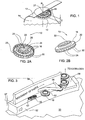
- FIG. 1 With reference to Fig. 1 , there is shown an integral in-line dripper 10 according to the invention, bonded during the extrusion process to an extruded irrigation pipe 12, at the internal surface 14 of the pipe.
- the dripper 10 has a top surface 16 designed for bonding to the internal surface 14 of the pipe 12, and a bottom surface 18 facing the inside of the pipe.
- the top surface 16 and the bottom surface 18 are connected by a peripheral surface 20. It will be appreciated that the terms “top” and “bottom” are purely conventional and pertain only to the orientation shown in Fig. 1 .
- the dripper 10 further has a meandering channel 22 carved in the top surface 16 of the dripper.
- the channel 22 has an inlet 24 and an outlet 26.
- the meandering channel 22 is covered by the internal surface 14 of the pipe to form a labyrinth, and an outlet 27 is formed in the pipe wall, aligned with the outlet 26 of the labyrinth.
- the top surface 16 must allow tight bonding of the pipe wall adjacent the meandering channel 22, so as to ensure that the labyrinth has closed cross-section.
- the dripper 10 further has a plurality of openings 28 in the peripheral surface 20, formed as radial passages between ribs 30, in fluid communication with the inlet 24 of the channel 22.
- openings 28 constitute a distributed filtering inlet.
- the dripper 10 has an annular wall (ring) 32 protruding from the bottom surface 18, which is used as a means for alignment.
- the drippers 10 come to a feeder 50 in arbitrary orientation.
- a rotary ring 52 drags the drippers, by frictional force, along a qualifying ring 54 towards a rejection cam 56.
- drippers oriented with the ring 32 upwards pass under the rejection cam 56 and proceed past a guiding rail 58 towards the extruder. Drippers with different orientation, as denoted by 10', are rejected back into the feeder.
- the vibratory force will move the drippers along the ring 52 and against the ring 54 which will be stationary relative to each other.
- the rejection cam 56 will operate in the same manner as above.
- the dripper 10, as well as all other drippers described below have more or less flattened shape such that their smallest dimension "d" is perpendicular to the pipe internal surface when bonded thereto.
- Their plan form i.e. the projection along that smallest dimension, or the contour when viewed from the bottom or the top surface, is circular, with diameter not exceeding the diameter of the pipe, assuming a circular pipe cross-section.
- the plan form may be just with approximately equal dimensions in all directions (isometric) or with circular symmetry. Even an elongated plan form may be used, if its longer dimension is about the pipe diameter or less.
- the dripper plan form and the top surface topography are designed to allow bonding of the dripper to the pipe wall in any orientation about a pipe radius R passing through the center of the top surface.
- the dripper 10 and some other drippers described below have a means for alignment of the dripper during pipe manufacture to ensure that its top surface faces the internal surface of the pipe before bonding. If the dripper has an axis of symmetry, the alignment means is preferably coaxial with that axis.
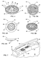
- Fig. 4 shows a dripper 35, similar to the dripper 10 except that its alignment means is in the form of cylindrical pin 29 at the top surface 16. The pin is combined with the dripper outlet 26 on the top surface 16.
- Figs. 5A and 5B show a dripper 40 where the filtering inlet is disposed on the bottom surface 18.
- a plurality of openings 42 are formed at crossings of parallel channels 44 made on the bottom surface 18, with an annular channel 46 made on the top surface beside the meandering channel.
- a circular step 48 at the bottom surface 18 is used as a means for alignment.
- Figs. 6A and 6B show a dripper 60, similar to the dripper 40, with the filtering inlet disposed on the bottom surface 68. Similar elements of the dripper 60 have the same numbers as the elements of the dripper 40. In this case, the bottom surface 68 is dome-shaped, which though having no step can still be used as a means for alignment. The process of alignment of the dripper 60 is shown in Fig. 7 .
- the feeder 50 is essentially the same as that shown in Fig. 3 , with a rotary ring 52, a qualifying ring 54, and a rejection cam 56. Between the qualifying ring 54 and the rotary ring 52 there is a gap 57 adapted to accommodate the thin edge of the dripper 60.
- the drippers oriented with the dome-shaped surface 68 upwards pass under the rejection cam 56, while drippers with opposite orientation, as denoted by 60', are rejected back into the feeder.
- any difference of shape between the top and the bottom surface of the dripper may be used for selection of properly aligned drippers in the feeder.
- Drippers according to the present invention may have no means and no need to be aligned before bonding to ensure that their top surface faces the pipe wall.
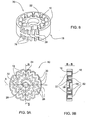
- Fig. 8 there is shown an integral in-line "double-faced" dripper 70 for irrigation pipe, where each of the top surface 16 and the bottom surface 18 is adapted for bonding to the internal surface of the pipe.
- the dripper 70 has two meandering channels 22 and 72, at the top and at the bottom surfaces, and two filtering inlets with openings 28 and 78 respectively. Owing to the flattened shape of the dripper, during the pipe manufacturing process, the dripper will always assume a position where one of its top and bottom surfaces faces the pipe wall, without special aligning means. Such dripper can be bonded to the pipe surface with either of the top and the bottom surfaces. In the example shown in Fig. 8 , the dripper is made with the bottom surface as mirror image of the top surface.
- Figs. 9A and 9B there is shown another integral in-line double-faced dripper 80 where both the top surface 16 and the bottom surface 18 are adapted for bonding to the internal surface 14 of the pipe.
- the whole top surface 16 including the meandering channel 22 and the outlet 26 is identical to the bottom surface but is so designed and disposed that recesses on the bottom surface match protrusions on the top surface and vice-versa.
- the topography of the bottom surface may be obtained by rotation of the top surface about the axis X.
- the topography of the top surface (the surface which must be bonded to the pipe) may be flat, convex (dome-shaped), etc. Indeed there is no need that the top surface exactly matches the inner cylindrical surface of an extruded pipe. But the design has to be such that, in the moment of bonding, when the extruded pipe is soft and flexible, it can accommodate the top surface at any orientation thereof.
- the plan form of the dripper is circular but it may have any shape with circular symmetry or with approximately equal length and width (isometric). As mentioned above, however, the largest dimension of the plan form is critical, so even an elongated shape may be used if it can be accommodated transversely to the pipe axis.
- the circular shape has the advantage to roll smoothly in the feeder and to allow faster alignment along the path to the extruder.
- the topography of the top surface, the plan form of the dripper and the layout of the filtering inlet, the meandering channel and the outlet should allow the dripper to be tightly bonded to the pipe wall in any orientation with respect to the pipe axis.
- means for alignment of the dripper before feeding to the extruded pipe may be such difference of shape as different roughness of the top and the bottom surface.
Landscapes
- Life Sciences & Earth Sciences (AREA)
- Soil Sciences (AREA)
- Engineering & Computer Science (AREA)
- Water Supply & Treatment (AREA)
- Environmental Sciences (AREA)
- Infusion, Injection, And Reservoir Apparatuses (AREA)
- Nozzles (AREA)
- Rigid Pipes And Flexible Pipes (AREA)
- Supply Of Fluid Materials To The Packaging Location (AREA)
- External Artificial Organs (AREA)
- Materials For Medical Uses (AREA)
- Investigating Or Analysing Biological Materials (AREA)
- Extrusion Moulding Of Plastics Or The Like (AREA)
Claims (20)
- Einteiliger Rohreinbau-Tropfkörper (10) mit abgeflachter Form, der geklebt an die Innenfläche (14) eines Bewässerungsrohrs (12) verwendet wird, wobei der Tropfkörper einen der Innenseite des Rohrs zugewandten Einlass sowie einen Auslass, der mit einer Auslassöffnung in der Rohrwand in einer Fluidkommunikation steht, eine erste Oberfläche (16), in der ein offener mäandernder Kanal (22) ausgebildet ist, wobei der Kanaleinlass (24) mit dem Tropfkörpereinlass in einer Fluidkommunikation steht, und eine zweite Oberfläche (18) gegenüber der ersten Oberfläche aufweist, dadurch gekennzeichnet, dass
die Topographie der ersten Oberfläche des Tropfkörpers so entworfen ist, dass der Tropfkörper in jeder Orientierung um einen Radius des durch die erste und die zweite Oberfläche verlaufenden Rohrs an die innere Oberfläche geklebt werden kann, wobei die innere Oberfläche den mäandernden Kanal dicht verschließt, um ein Strömungsbegrenzungslabyrinth mit einem Auslass zu bilden, der den Auslass des Tropfkörpers bildet oder mit diesem in einer Fluidkommunikation steht. - Tropfkörper nach Anspruch 1, der ferner ein Mittel besitzt, um ihn vor dem Kleben auszurichten, so dass die erste Oberfläche der inneren Oberfläche des Rohrs zugewandt ist.
- Tropfkörper nach Anspruch 2, wobei die erste Oberfläche und die zweite Oberfläche unterschiedliche Formen haben, so dass der Formunterschied als das Ausrichtmittel verwendet werden kann.
- Tropfkörper nach Anspruch 3, wobei das Ausrichtmittel eine Stufe ist, die von der zweiten Oberfläche vorsteht.
- Tropfkörper nach Anspruch 4, wobei die erste und die zweite Oberfläche in der Draufsicht im Allgemeinen Kreissymmetrie haben und die Stufe kreisförmig und zu der Symmetrieachse koaxial ist.
- Tropfkörper nach Anspruch 5, wobei die kreisförmige Stufe eine ringförmige Wand ist.
- Tropfkörper nach Anspruch 3, wobei die Ausrichtmittel ein zylindrischer Stift sind, der von der ersten oder der zweiten Oberfläche vorsteht.
- Tropfkörper nach Anspruch 3, wobei die erste oder die zweite Oberfläche stärker konvex als die jeweils andere Oberfläche ist.
- Tropfkörper nach Anspruch 1, wobei der Tropfkörpereinlass ein Filterungseinlass ist, der mehrere Öffnungen umfasst, die an der zweiten Oberfläche oder an einer Umfangsoberfläche, die die erste und die zweite Oberfläche miteinander verbindet, angeordnet sind.
- Tropfkörper nach Anspruch 9, wobei der Filterungseinlass durch mehrere radiale Durchlässe an der ersten Oberfläche gebildet ist, die durch die innere Oberfläche des Rohrs ergänzt werden und in den mehreren Öffnungen beginnen.
- Tropfkörper nach Anspruch 1, wobei die erste Oberfläche eben oder kuppelförmig ist.
- Tropfkörper nach Anspruch 1, wobei die erste Oberfläche in der Draufsicht im Wesentlichen isometrisch ist.
- Tropfkörper nach Anspruch 12, wobei die erste Oberfläche in der Draufsicht im Allgemeinen Kreissymmetrie hat.
- Tropfkörper nach Anspruch 13, wobei die erste Oberfläche in der Draufsicht kreisförmig ist.
- Tropfkörper nach Anspruch 1, wobei die zweite Oberfläche einen zweiten mäandernden Kanal und eine Topographie besitzt, die so entworfen ist, dass sie zu jener der ersten Oberfläche ähnlich ist, so dass der Tropfkörper entweder mit der ersten oder mit der zweiten Oberfläche in jeder Orientierung um einen Radius des durch die erste und die zweite Oberfläche verlaufenden Rohrs an die innere Oberfläche des Rohrs geklebt werden kann, wobei die innere Oberfläche den jeweiligen mäandernden Kanal dicht verschließt, um das Strömungsbegrenzungslabyrinth zu bilden.
- Tropfkörper nach Anspruch 15, wobei die zweite Oberfläche im Wesentlichen ein Spiegelbild der ersten Oberfläche ist.
- Tropfkörper nach Anspruch 15, wobei die zweite Oberfläche mit der ersten Oberfläche im Wesentlichen übereinstimmt und so angeordnet ist, dass Aussparungen in der zweiten Oberfläche mit Vorsprüngen an der ersten Oberfläche übereinstimmen und umgekehrt.
- Einteiliger Rohreinbau-Tropfkörper (10) mit ebener Form, der geklebt an die innere Oberfläche (14) eines Bewässerungsrohrs zu verwenden ist, wobei der Tropfkörper einen der Innenseite des Rohrs zugewandten Einlass und einen Auslass, der mit einer Auslassöffnung in der Rohrwand in einer Fluidkommunikation steht, aufweist, wobei die ebene Form zwischen einer ersten und einer zweiten Oberfläche (16, 18) definiert ist, dadurch gekennzeichnet, dass die Topographie jeder der zwei Oberflächen so entworfen ist, dass der Tropfkörper entweder mit der ersten oder mit der zweiten Oberfläche in jeder Orientierung um einen Radius des durch die erste und die zweite Oberfläche verlaufenden Rohrs an die innere Oberfläche des Rohrs geklebt werden kann.
- Tropfkörper nach Anspruch 18, wobei der Tropfkörper ein Strömungsbegrenzungslabyrinth aufweist, das mit dem Einlass und dem Auslass des Tropfkörpers in einer Fluidkommunikation steht.
- Bewässerungsrohr (12) mit einteiligen Rohreinbau-Tropfkörpern (10) mit ebener Form, die mit der ersten Oberfläche (16) der Tropfkörper an die innere Oberfläche (14) des Rohrs geklebt sind, wobei die erste Oberfläche einen darin ausgebildeten offenen mäandernden Kanal (22) besitzt, der durch die innere Oberfläche dicht verschlossen ist, um ein Strömungsbegrenzungslabyrinth zu bilden, dadurch gekennzeichnet, dass die ebene Form in der Draufsicht im Wesentlichen isometrisch oder lang gestreckt ist, wobei wenigstens einige der Tropfkörper mit ihrer langen Abmessung nicht parallel zu der Achse des Rohrs angeklebt sind.
Applications Claiming Priority (2)
| Application Number | Priority Date | Filing Date | Title |
|---|---|---|---|
| US10/871,529 US7270280B2 (en) | 2004-06-21 | 2004-06-21 | Disc shape dripper |
| PCT/IL2005/000662 WO2005122747A2 (en) | 2004-06-21 | 2005-06-21 | Disc shape dripper |
Publications (2)
| Publication Number | Publication Date |
|---|---|
| EP1765054A2 EP1765054A2 (de) | 2007-03-28 |
| EP1765054B1 true EP1765054B1 (de) | 2009-09-16 |
Family
ID=34979059
Family Applications (1)
| Application Number | Title | Priority Date | Filing Date |
|---|---|---|---|
| EP05754584A Expired - Lifetime EP1765054B1 (de) | 2004-06-21 | 2005-06-21 | Scheibenförmige tropfbewässerungsvorrichtung |
Country Status (16)
| Country | Link |
|---|---|
| US (1) | US7270280B2 (de) |
| EP (1) | EP1765054B1 (de) |
| JP (1) | JP2008503232A (de) |
| KR (1) | KR100970811B1 (de) |
| CN (1) | CN101014238B (de) |
| AT (1) | ATE442772T1 (de) |
| AU (1) | AU2005253817C1 (de) |
| BR (1) | BRPI0512343B1 (de) |
| DE (1) | DE602005016679D1 (de) |
| ES (1) | ES2332185T3 (de) |
| MA (1) | MA28743B1 (de) |
| MX (1) | MXPA06014822A (de) |
| RU (1) | RU2370946C2 (de) |
| UA (1) | UA92588C2 (de) |
| WO (1) | WO2005122747A2 (de) |
| ZA (1) | ZA200609960B (de) |
Families Citing this family (43)
| Publication number | Priority date | Publication date | Assignee | Title |
|---|---|---|---|---|
| US20060186228A1 (en) | 2005-02-23 | 2006-08-24 | Belford James W | Irrigation dripper and pipe |
| US8302887B2 (en) | 2005-03-31 | 2012-11-06 | Rain Bird Corporation | Drip emitter |
| US7648085B2 (en) | 2006-02-22 | 2010-01-19 | Rain Bird Corporation | Drip emitter |
| US20090151798A1 (en) * | 2007-12-17 | 2009-06-18 | Harned Fred H | Irrigation system emitter |
| WO2010055530A1 (en) * | 2008-11-11 | 2010-05-20 | La.Re.Ter. S.P.A. | Device for the control of the flow of dripping irrigation hoses |
| US8628032B2 (en) | 2008-12-31 | 2014-01-14 | Rain Bird Corporation | Low flow irrigation emitter |
| US8511586B2 (en) | 2011-04-20 | 2013-08-20 | Deere & Company | Disc shaped regulated drip irrigation emitter |
| US10440903B2 (en) | 2012-03-26 | 2019-10-15 | Rain Bird Corporation | Drip line emitter and methods relating to same |
| US9485923B2 (en) | 2012-03-26 | 2016-11-08 | Rain Bird Corporation | Elastomeric emitter and methods relating to same |
| US9877440B2 (en) | 2012-03-26 | 2018-01-30 | Rain Bird Corporation | Elastomeric emitter and methods relating to same |
| US20130248622A1 (en) | 2012-03-26 | 2013-09-26 | Jae Yung Kim | Drip line and emitter and methods relating to same |
| EP2893801B1 (de) * | 2012-09-06 | 2018-03-14 | Enplas Corporation | Tropfbewässerungstropfer und tropfbewässerungsvorrichtung damit |
| JP5629739B2 (ja) | 2012-09-14 | 2014-11-26 | トヨタ自動車株式会社 | 車体前部構造 |
| JP5983384B2 (ja) | 2012-12-12 | 2016-08-31 | トヨタ自動車株式会社 | 車体後部構造 |
| ES2697201T3 (es) * | 2012-12-17 | 2019-01-22 | Enplas Corp | Gotero de irrigación por goteo y dispositivo de irrigación por goteo provisto con el mismo |
| CN103968182B (zh) * | 2013-01-25 | 2016-03-02 | 林文斌 | 迷宫式节流器 |
| US9872444B2 (en) | 2013-03-15 | 2018-01-23 | Rain Bird Corporation | Drip emitter |
| JP5854021B2 (ja) | 2013-03-27 | 2016-02-09 | トヨタ自動車株式会社 | ホイルハウス後部構造 |
| US9949448B2 (en) * | 2015-01-14 | 2018-04-24 | Amirim Products Development & Patents Ltd. | Modular in line button drip emitter system |
| US9462760B2 (en) | 2013-07-09 | 2016-10-11 | Amirim Products Development & Patents Ltd. | In line button drip emitter |
| US10869434B2 (en) | 2013-07-09 | 2020-12-22 | Amirim Products Development & Patents Ltd. | Elliptical in line button dripper with extended bonding zones |
| US10285342B2 (en) | 2013-08-12 | 2019-05-14 | Rain Bird Corporation | Elastomeric emitter and methods relating to same |
| USD811179S1 (en) | 2013-08-12 | 2018-02-27 | Rain Bird Corporation | Emitter part |
| US10631473B2 (en) | 2013-08-12 | 2020-04-28 | Rain Bird Corporation | Elastomeric emitter and methods relating to same |
| US9307705B2 (en) | 2013-10-02 | 2016-04-12 | Eurodrip Industrial Commercial Agricultural Societe Anonyme | Pressure compensating drip irrigation emitter |
| US9380749B2 (en) | 2013-10-02 | 2016-07-05 | Eurodrip Industrial Commercial Agricultural Societe Anonyme | Drip tape irrigation emitter |
| US9883640B2 (en) | 2013-10-22 | 2018-02-06 | Rain Bird Corporation | Methods and apparatus for transporting elastomeric emitters and/or manufacturing drip lines |
| US10330559B2 (en) | 2014-09-11 | 2019-06-25 | Rain Bird Corporation | Methods and apparatus for checking emitter bonds in an irrigation drip line |
| GR20140100517A (el) | 2014-10-13 | 2016-06-01 | Εμμανουηλ Αριστειδη Δερμιτζακης | Υβριδικος διανεμητης και μεθοδος ενσωματωσης σταλακτων και εξαρτηματων σε αρδευτικο αγωγο |
| IL251621A0 (en) * | 2016-04-07 | 2017-06-29 | Cohen Amir | Button dripper for irrigation lines |
| US10375904B2 (en) | 2016-07-18 | 2019-08-13 | Rain Bird Corporation | Emitter locating system and related methods |
| KR101828596B1 (ko) * | 2016-08-05 | 2018-02-13 | 주식회사 남경 | 압력보상 드립 이미터 |
| US11051466B2 (en) | 2017-01-27 | 2021-07-06 | Rain Bird Corporation | Pressure compensation members, emitters, drip line and methods relating to same |
| US10626998B2 (en) | 2017-05-15 | 2020-04-21 | Rain Bird Corporation | Drip emitter with check valve |
| USD883048S1 (en) | 2017-12-12 | 2020-05-05 | Rain Bird Corporation | Emitter part |
| US11985924B2 (en) | 2018-06-11 | 2024-05-21 | Rain Bird Corporation | Emitter outlet, emitter, drip line and methods relating to same |
| CN109737262B (zh) * | 2019-01-18 | 2024-07-26 | 华北电力大学 | 阶梯迷宫型节流件 |
| US11933417B2 (en) | 2019-09-27 | 2024-03-19 | Rain Bird Corporation | Irrigation sprinkler service valve |
| US12030072B2 (en) | 2020-11-16 | 2024-07-09 | Rain Bird Corporation | Pressure regulation device and method for irrigation sprinklers |
| US12207599B2 (en) | 2021-10-12 | 2025-01-28 | Rain Bird Corporation | Emitter coupler and irrigation system |
| CN218302649U (zh) * | 2022-06-17 | 2023-01-17 | 天津市华旭盛泰科技有限公司 | 一种易安装灌溉滴头 |
| CN115055699B (zh) * | 2022-06-24 | 2024-03-29 | 西安交通大学 | 颗粒增强铝基复合材料熔滴复合电弧增材制造装置及方法 |
| IL309683A (en) * | 2023-12-24 | 2025-07-01 | Rivulis Plastro Ltd | Single-component, integral, disc-shaped, regulating dripper |
Family Cites Families (10)
| Publication number | Priority date | Publication date | Assignee | Title |
|---|---|---|---|---|
| IL45466A (en) * | 1974-08-14 | 1976-07-30 | Hydro Plan Eng Ltd | Drip irrigation |
| IL93255A (en) | 1990-02-02 | 1997-03-18 | Plastro Gvat | Drip irrigation lines |
| GR1001008B (el) | 1990-10-03 | 1993-03-31 | Emmanouil Dermitzakis | Σταλακτοφόρος σωλήνας με εσωτερικά επικολλημένους σταλάκτες και μέ?οδος κατασκευής του. |
| IL95972A (en) | 1990-10-12 | 1993-03-15 | Naan Irrigation Systems | Method and apparatus for producing pipes for drip irrigation |
| IL119237A (en) | 1996-09-11 | 1998-10-30 | Gvat Plastro | Flow-regulating element and drip irrigation units utilizing same |
| RU2129775C1 (ru) * | 1997-06-17 | 1999-05-10 | Всероссийский научно-исследовательский институт гидротехники и мелиорации им.А.Н.Костякова | Устройство для комбинированного микроорошения |
| US6213408B1 (en) * | 1999-11-18 | 2001-04-10 | Eureka Technologies Ltd | Flow regulator and corresponding method with pressure responsive flow regulation |
| US6886761B2 (en) | 2000-08-21 | 2005-05-03 | Amir Cohen | Drip irrigation hose and method and apparatus for making same |
| US20020104902A1 (en) * | 2001-02-08 | 2002-08-08 | Eran Eckstein | Inline dripper with micro-tube connector |
| RU2219760C1 (ru) * | 2002-06-24 | 2003-12-27 | Государственное научное учреждение Поволжский научно-исследовательский институт эколого-мелиоративных технологий | Система капельного орошения |
-
2004
- 2004-06-21 US US10/871,529 patent/US7270280B2/en not_active Expired - Lifetime
-
2005
- 2005-06-21 DE DE602005016679T patent/DE602005016679D1/de not_active Expired - Fee Related
- 2005-06-21 RU RU2007101057/12A patent/RU2370946C2/ru active
- 2005-06-21 BR BRPI0512343-7A patent/BRPI0512343B1/pt not_active IP Right Cessation
- 2005-06-21 AT AT05754584T patent/ATE442772T1/de not_active IP Right Cessation
- 2005-06-21 KR KR1020077001480A patent/KR100970811B1/ko not_active Expired - Fee Related
- 2005-06-21 JP JP2007517649A patent/JP2008503232A/ja active Pending
- 2005-06-21 UA UAA200700546A patent/UA92588C2/ru unknown
- 2005-06-21 MX MXPA06014822A patent/MXPA06014822A/es active IP Right Grant
- 2005-06-21 CN CN2005800206107A patent/CN101014238B/zh not_active Expired - Fee Related
- 2005-06-21 ES ES05754584T patent/ES2332185T3/es not_active Expired - Lifetime
- 2005-06-21 EP EP05754584A patent/EP1765054B1/de not_active Expired - Lifetime
- 2005-06-21 WO PCT/IL2005/000662 patent/WO2005122747A2/en not_active Ceased
- 2005-06-21 AU AU2005253817A patent/AU2005253817C1/en not_active Ceased
-
2006
- 2006-11-29 ZA ZA200609960A patent/ZA200609960B/xx unknown
-
2007
- 2007-01-18 MA MA29621A patent/MA28743B1/fr unknown
Also Published As
| Publication number | Publication date |
|---|---|
| WO2005122747A2 (en) | 2005-12-29 |
| WO2005122747A3 (en) | 2006-02-23 |
| KR100970811B1 (ko) | 2010-07-16 |
| MA28743B1 (fr) | 2007-07-02 |
| RU2007101057A (ru) | 2008-07-27 |
| EP1765054A2 (de) | 2007-03-28 |
| BRPI0512343A (pt) | 2008-03-04 |
| US20050279866A1 (en) | 2005-12-22 |
| AU2005253817C1 (en) | 2009-09-24 |
| AU2005253817B2 (en) | 2009-02-26 |
| ATE442772T1 (de) | 2009-10-15 |
| CN101014238B (zh) | 2010-05-05 |
| BRPI0512343B1 (pt) | 2014-04-15 |
| CN101014238A (zh) | 2007-08-08 |
| RU2370946C2 (ru) | 2009-10-27 |
| DE602005016679D1 (de) | 2009-10-29 |
| JP2008503232A (ja) | 2008-02-07 |
| AU2005253817A1 (en) | 2005-12-29 |
| MXPA06014822A (es) | 2007-03-23 |
| US7270280B2 (en) | 2007-09-18 |
| ZA200609960B (en) | 2008-01-30 |
| KR20070064423A (ko) | 2007-06-20 |
| UA92588C2 (ru) | 2010-11-25 |
| ES2332185T3 (es) | 2010-01-28 |
Similar Documents
| Publication | Publication Date | Title |
|---|---|---|
| US7270280B2 (en) | Disc shape dripper | |
| JPH0317644B2 (de) | ||
| USD1016236S1 (en) | Tap | |
| EP4223131A1 (de) | Mikrokanalgefrierzylinderanordnung | |
| EP0120716A2 (de) | Strangpressmundstück | |
| EP0275162B1 (de) | Mundstück zum Extrudieren einer Wabenstruktur | |
| JPH10500361A (ja) | 連続押し出し装置 | |
| WO2019065424A1 (ja) | エミッタおよび点滴灌漑用チューブ | |
| WO1992003275A1 (en) | Coextrusion method and apparatus | |
| WO2003041829A3 (en) | Filter module and method for its manufacture | |
| US12377595B2 (en) | Extrusion and/or pultrusion device and method | |
| IL179353A (en) | Disc-shaped dripper | |
| JPH02269023A (ja) | 少なくとも1つの長手方向通路を含む有機材料の膜の製造用ダイス | |
| AU749567B2 (en) | Mold block with air flow control | |
| USD1104591S1 (en) | Drinking glass | |
| EP1089104A1 (de) | Faseroptische Trommel, Vorratsvorrichtung für optische Faser und optischer Verstärker | |
| JPS62273818A (ja) | 同時押し出し機 | |
| JP2001269979A (ja) | 層順序選択装置 | |
| WO2017159251A1 (ja) | エミッタおよび点滴灌漑用チューブ | |
| WO2021100607A1 (ja) | エミッタおよび点滴灌漑用チューブ | |
| US6148861A (en) | Multiway valve for fluids and its use | |
| JP2005090555A (ja) | 減圧調節弁 | |
| USD1110974S1 (en) | Antenna | |
| USD1105558S1 (en) | Sconce | |
| USD1117635S1 (en) | Irrigation valve |
Legal Events
| Date | Code | Title | Description |
|---|---|---|---|
| PUAI | Public reference made under article 153(3) epc to a published international application that has entered the european phase |
Free format text: ORIGINAL CODE: 0009012 |
|
| 17P | Request for examination filed |
Effective date: 20061220 |
|
| AK | Designated contracting states |
Kind code of ref document: A2 Designated state(s): AT BE BG CH CY CZ DE DK EE ES FI FR GB GR HU IE IS IT LI LT LU MC NL PL PT RO SE SI SK TR |
|
| DAX | Request for extension of the european patent (deleted) | ||
| 17Q | First examination report despatched |
Effective date: 20080804 |
|
| GRAP | Despatch of communication of intention to grant a patent |
Free format text: ORIGINAL CODE: EPIDOSNIGR1 |
|
| GRAS | Grant fee paid |
Free format text: ORIGINAL CODE: EPIDOSNIGR3 |
|
| GRAA | (expected) grant |
Free format text: ORIGINAL CODE: 0009210 |
|
| AK | Designated contracting states |
Kind code of ref document: B1 Designated state(s): AT BE BG CH CY CZ DE DK EE ES FI FR GB GR HU IE IS IT LI LT LU MC NL PL PT RO SE SI SK TR |
|
| REG | Reference to a national code |
Ref country code: GB Ref legal event code: FG4D |
|
| REG | Reference to a national code |
Ref country code: CH Ref legal event code: EP |
|
| REG | Reference to a national code |
Ref country code: IE Ref legal event code: FG4D |
|
| REF | Corresponds to: |
Ref document number: 602005016679 Country of ref document: DE Date of ref document: 20091029 Kind code of ref document: P |
|
| REG | Reference to a national code |
Ref country code: GR Ref legal event code: EP Ref document number: 20090402870 Country of ref document: GR |
|
| REG | Reference to a national code |
Ref country code: ES Ref legal event code: FG2A Ref document number: 2332185 Country of ref document: ES Kind code of ref document: T3 |
|
| PG25 | Lapsed in a contracting state [announced via postgrant information from national office to epo] |
Ref country code: SE Free format text: LAPSE BECAUSE OF FAILURE TO SUBMIT A TRANSLATION OF THE DESCRIPTION OR TO PAY THE FEE WITHIN THE PRESCRIBED TIME-LIMIT Effective date: 20090916 Ref country code: FI Free format text: LAPSE BECAUSE OF FAILURE TO SUBMIT A TRANSLATION OF THE DESCRIPTION OR TO PAY THE FEE WITHIN THE PRESCRIBED TIME-LIMIT Effective date: 20090916 Ref country code: LT Free format text: LAPSE BECAUSE OF FAILURE TO SUBMIT A TRANSLATION OF THE DESCRIPTION OR TO PAY THE FEE WITHIN THE PRESCRIBED TIME-LIMIT Effective date: 20090916 |
|
| LTIE | Lt: invalidation of european patent or patent extension |
Effective date: 20090916 |
|
| PG25 | Lapsed in a contracting state [announced via postgrant information from national office to epo] |
Ref country code: NL Free format text: LAPSE BECAUSE OF FAILURE TO SUBMIT A TRANSLATION OF THE DESCRIPTION OR TO PAY THE FEE WITHIN THE PRESCRIBED TIME-LIMIT Effective date: 20090916 Ref country code: PL Free format text: LAPSE BECAUSE OF FAILURE TO SUBMIT A TRANSLATION OF THE DESCRIPTION OR TO PAY THE FEE WITHIN THE PRESCRIBED TIME-LIMIT Effective date: 20090916 Ref country code: SI Free format text: LAPSE BECAUSE OF FAILURE TO SUBMIT A TRANSLATION OF THE DESCRIPTION OR TO PAY THE FEE WITHIN THE PRESCRIBED TIME-LIMIT Effective date: 20090916 |
|
| NLV1 | Nl: lapsed or annulled due to failure to fulfill the requirements of art. 29p and 29m of the patents act | ||
| PG25 | Lapsed in a contracting state [announced via postgrant information from national office to epo] |
Ref country code: CY Free format text: LAPSE BECAUSE OF FAILURE TO SUBMIT A TRANSLATION OF THE DESCRIPTION OR TO PAY THE FEE WITHIN THE PRESCRIBED TIME-LIMIT Effective date: 20090916 |
|
| PG25 | Lapsed in a contracting state [announced via postgrant information from national office to epo] |
Ref country code: EE Free format text: LAPSE BECAUSE OF FAILURE TO SUBMIT A TRANSLATION OF THE DESCRIPTION OR TO PAY THE FEE WITHIN THE PRESCRIBED TIME-LIMIT Effective date: 20090916 Ref country code: PT Free format text: LAPSE BECAUSE OF FAILURE TO SUBMIT A TRANSLATION OF THE DESCRIPTION OR TO PAY THE FEE WITHIN THE PRESCRIBED TIME-LIMIT Effective date: 20100118 Ref country code: CZ Free format text: LAPSE BECAUSE OF FAILURE TO SUBMIT A TRANSLATION OF THE DESCRIPTION OR TO PAY THE FEE WITHIN THE PRESCRIBED TIME-LIMIT Effective date: 20090916 Ref country code: RO Free format text: LAPSE BECAUSE OF FAILURE TO SUBMIT A TRANSLATION OF THE DESCRIPTION OR TO PAY THE FEE WITHIN THE PRESCRIBED TIME-LIMIT Effective date: 20090916 Ref country code: IS Free format text: LAPSE BECAUSE OF FAILURE TO SUBMIT A TRANSLATION OF THE DESCRIPTION OR TO PAY THE FEE WITHIN THE PRESCRIBED TIME-LIMIT Effective date: 20100116 |
|
| PG25 | Lapsed in a contracting state [announced via postgrant information from national office to epo] |
Ref country code: SK Free format text: LAPSE BECAUSE OF FAILURE TO SUBMIT A TRANSLATION OF THE DESCRIPTION OR TO PAY THE FEE WITHIN THE PRESCRIBED TIME-LIMIT Effective date: 20090916 |
|
| PG25 | Lapsed in a contracting state [announced via postgrant information from national office to epo] |
Ref country code: BE Free format text: LAPSE BECAUSE OF FAILURE TO SUBMIT A TRANSLATION OF THE DESCRIPTION OR TO PAY THE FEE WITHIN THE PRESCRIBED TIME-LIMIT Effective date: 20090916 Ref country code: AT Free format text: LAPSE BECAUSE OF FAILURE TO SUBMIT A TRANSLATION OF THE DESCRIPTION OR TO PAY THE FEE WITHIN THE PRESCRIBED TIME-LIMIT Effective date: 20090916 |
|
| PLBE | No opposition filed within time limit |
Free format text: ORIGINAL CODE: 0009261 |
|
| STAA | Information on the status of an ep patent application or granted ep patent |
Free format text: STATUS: NO OPPOSITION FILED WITHIN TIME LIMIT |
|
| PG25 | Lapsed in a contracting state [announced via postgrant information from national office to epo] |
Ref country code: DK Free format text: LAPSE BECAUSE OF FAILURE TO SUBMIT A TRANSLATION OF THE DESCRIPTION OR TO PAY THE FEE WITHIN THE PRESCRIBED TIME-LIMIT Effective date: 20090916 |
|
| 26N | No opposition filed |
Effective date: 20100617 |
|
| PG25 | Lapsed in a contracting state [announced via postgrant information from national office to epo] |
Ref country code: MC Free format text: LAPSE BECAUSE OF NON-PAYMENT OF DUE FEES Effective date: 20100630 |
|
| REG | Reference to a national code |
Ref country code: CH Ref legal event code: PL |
|
| GBPC | Gb: european patent ceased through non-payment of renewal fee |
Effective date: 20100621 |
|
| PG25 | Lapsed in a contracting state [announced via postgrant information from national office to epo] |
Ref country code: LI Free format text: LAPSE BECAUSE OF NON-PAYMENT OF DUE FEES Effective date: 20100630 Ref country code: DE Free format text: LAPSE BECAUSE OF NON-PAYMENT OF DUE FEES Effective date: 20110101 Ref country code: CH Free format text: LAPSE BECAUSE OF NON-PAYMENT OF DUE FEES Effective date: 20100630 Ref country code: IE Free format text: LAPSE BECAUSE OF NON-PAYMENT OF DUE FEES Effective date: 20100621 |
|
| PG25 | Lapsed in a contracting state [announced via postgrant information from national office to epo] |
Ref country code: GB Free format text: LAPSE BECAUSE OF NON-PAYMENT OF DUE FEES Effective date: 20100621 |
|
| PG25 | Lapsed in a contracting state [announced via postgrant information from national office to epo] |
Ref country code: BG Free format text: LAPSE BECAUSE OF FAILURE TO SUBMIT A TRANSLATION OF THE DESCRIPTION OR TO PAY THE FEE WITHIN THE PRESCRIBED TIME-LIMIT Effective date: 20090916 Ref country code: HU Free format text: LAPSE BECAUSE OF FAILURE TO SUBMIT A TRANSLATION OF THE DESCRIPTION OR TO PAY THE FEE WITHIN THE PRESCRIBED TIME-LIMIT Effective date: 20100317 Ref country code: LU Free format text: LAPSE BECAUSE OF NON-PAYMENT OF DUE FEES Effective date: 20100621 |
|
| REG | Reference to a national code |
Ref country code: FR Ref legal event code: PLFP Year of fee payment: 12 |
|
| REG | Reference to a national code |
Ref country code: FR Ref legal event code: PLFP Year of fee payment: 13 |
|
| REG | Reference to a national code |
Ref country code: FR Ref legal event code: PLFP Year of fee payment: 14 |
|
| PGFP | Annual fee paid to national office [announced via postgrant information from national office to epo] |
Ref country code: GR Payment date: 20200611 Year of fee payment: 16 Ref country code: FR Payment date: 20200619 Year of fee payment: 16 Ref country code: TR Payment date: 20200619 Year of fee payment: 16 |
|
| PGFP | Annual fee paid to national office [announced via postgrant information from national office to epo] |
Ref country code: ES Payment date: 20200824 Year of fee payment: 16 |
|
| PGFP | Annual fee paid to national office [announced via postgrant information from national office to epo] |
Ref country code: IT Payment date: 20200625 Year of fee payment: 16 |
|
| PG25 | Lapsed in a contracting state [announced via postgrant information from national office to epo] |
Ref country code: GR Free format text: LAPSE BECAUSE OF NON-PAYMENT OF DUE FEES Effective date: 20220105 Ref country code: FR Free format text: LAPSE BECAUSE OF NON-PAYMENT OF DUE FEES Effective date: 20210630 |
|
| PG25 | Lapsed in a contracting state [announced via postgrant information from national office to epo] |
Ref country code: IT Free format text: LAPSE BECAUSE OF NON-PAYMENT OF DUE FEES Effective date: 20210621 |
|
| REG | Reference to a national code |
Ref country code: ES Ref legal event code: FD2A Effective date: 20220805 |
|
| PG25 | Lapsed in a contracting state [announced via postgrant information from national office to epo] |
Ref country code: ES Free format text: LAPSE BECAUSE OF NON-PAYMENT OF DUE FEES Effective date: 20210622 |
|
| PG25 | Lapsed in a contracting state [announced via postgrant information from national office to epo] |
Ref country code: TR Free format text: LAPSE BECAUSE OF NON-PAYMENT OF DUE FEES Effective date: 20210621 |