EP1765644B1 - Airbag - Google Patents
Airbag Download PDFInfo
- Publication number
- EP1765644B1 EP1765644B1 EP05752730A EP05752730A EP1765644B1 EP 1765644 B1 EP1765644 B1 EP 1765644B1 EP 05752730 A EP05752730 A EP 05752730A EP 05752730 A EP05752730 A EP 05752730A EP 1765644 B1 EP1765644 B1 EP 1765644B1
- Authority
- EP
- European Patent Office
- Prior art keywords
- bag
- air
- gas generator
- stud
- receive
- Prior art date
- Legal status (The legal status is an assumption and is not a legal conclusion. Google has not performed a legal analysis and makes no representation as to the accuracy of the status listed.)
- Expired - Lifetime
Links
Images

Classifications
-
- B—PERFORMING OPERATIONS; TRANSPORTING
- B60—VEHICLES IN GENERAL
- B60N—SEATS SPECIALLY ADAPTED FOR VEHICLES; VEHICLE PASSENGER ACCOMMODATION NOT OTHERWISE PROVIDED FOR
- B60N2/00—Seats specially adapted for vehicles; Arrangement or mounting of seats in vehicles
- B60N2/24—Seats specially adapted for vehicles; Arrangement or mounting of seats in vehicles for particular purposes or particular vehicles
- B60N2/42—Seats specially adapted for vehicles; Arrangement or mounting of seats in vehicles for particular purposes or particular vehicles the seat constructed to protect the occupant from the effect of abnormal g-forces, e.g. crash or safety seats
- B60N2/427—Seats or parts thereof displaced during a crash
- B60N2/42709—Seats or parts thereof displaced during a crash involving residual deformation or fracture of the structure
- B60N2/42718—Seats or parts thereof displaced during a crash involving residual deformation or fracture of the structure with anti-submarining systems
-
- B—PERFORMING OPERATIONS; TRANSPORTING
- B60—VEHICLES IN GENERAL
- B60R—VEHICLES, VEHICLE FITTINGS, OR VEHICLE PARTS, NOT OTHERWISE PROVIDED FOR
- B60R21/00—Arrangements or fittings on vehicles for protecting or preventing injuries to occupants or pedestrians in case of accidents or other traffic risks
- B60R21/02—Occupant safety arrangements or fittings, e.g. crash pads
- B60R21/16—Inflatable occupant restraints or confinements designed to inflate upon impact or impending impact, e.g. air bags
- B60R21/23—Inflatable members
- B60R21/235—Inflatable members characterised by their material
-
- B—PERFORMING OPERATIONS; TRANSPORTING
- B60—VEHICLES IN GENERAL
- B60R—VEHICLES, VEHICLE FITTINGS, OR VEHICLE PARTS, NOT OTHERWISE PROVIDED FOR
- B60R21/00—Arrangements or fittings on vehicles for protecting or preventing injuries to occupants or pedestrians in case of accidents or other traffic risks
- B60R21/02—Occupant safety arrangements or fittings, e.g. crash pads
- B60R21/16—Inflatable occupant restraints or confinements designed to inflate upon impact or impending impact, e.g. air bags
- B60R21/23—Inflatable members
- B60R21/235—Inflatable members characterised by their material
- B60R2021/23504—Inflatable members characterised by their material characterised by material
- B60R2021/23519—Resin
-
- B—PERFORMING OPERATIONS; TRANSPORTING
- B60—VEHICLES IN GENERAL
- B60R—VEHICLES, VEHICLE FITTINGS, OR VEHICLE PARTS, NOT OTHERWISE PROVIDED FOR
- B60R21/00—Arrangements or fittings on vehicles for protecting or preventing injuries to occupants or pedestrians in case of accidents or other traffic risks
- B60R21/02—Occupant safety arrangements or fittings, e.g. crash pads
- B60R21/16—Inflatable occupant restraints or confinements designed to inflate upon impact or impending impact, e.g. air bags
- B60R21/23—Inflatable members
- B60R21/235—Inflatable members characterised by their material
- B60R2021/23504—Inflatable members characterised by their material characterised by material
- B60R2021/23528—Metal
-
- B—PERFORMING OPERATIONS; TRANSPORTING
- B60—VEHICLES IN GENERAL
- B60R—VEHICLES, VEHICLE FITTINGS, OR VEHICLE PARTS, NOT OTHERWISE PROVIDED FOR
- B60R21/00—Arrangements or fittings on vehicles for protecting or preventing injuries to occupants or pedestrians in case of accidents or other traffic risks
- B60R21/02—Occupant safety arrangements or fittings, e.g. crash pads
- B60R21/16—Inflatable occupant restraints or confinements designed to inflate upon impact or impending impact, e.g. air bags
- B60R21/20—Arrangements for storing inflatable members in their non-use or deflated condition; Arrangement or mounting of air bag modules or components
- B60R21/217—Inflation fluid source retainers, e.g. reaction canisters; Connection of bags, covers, diffusers or inflation fluid sources therewith or together
- B60R21/2171—Inflation fluid source retainers, e.g. reaction canisters; Connection of bags, covers, diffusers or inflation fluid sources therewith or together specially adapted for elongated cylindrical or bottle-like inflators with a symmetry axis perpendicular to the main direction of bag deployment, e.g. extruded reaction canisters
-
- B—PERFORMING OPERATIONS; TRANSPORTING
- B60—VEHICLES IN GENERAL
- B60R—VEHICLES, VEHICLE FITTINGS, OR VEHICLE PARTS, NOT OTHERWISE PROVIDED FOR
- B60R21/00—Arrangements or fittings on vehicles for protecting or preventing injuries to occupants or pedestrians in case of accidents or other traffic risks
- B60R21/02—Occupant safety arrangements or fittings, e.g. crash pads
- B60R21/16—Inflatable occupant restraints or confinements designed to inflate upon impact or impending impact, e.g. air bags
- B60R21/23—Inflatable members
- B60R21/239—Inflatable members characterised by their venting means
Definitions
- THE PRESENT INVENTION relates to arrangement with an an air-bag formed from a substantially rigid material with the features of the preamble of claim 1 which are known from WO-00/50270A1 .
- air-bags of substantially rigid material such as, for example, a blow-moulded plastics material.
- a blow-moulded plastics material air-bag for use as a pelvic restraint cushion.
- air-bags of metal it has been proposed to use air-bags of metal.
- a pelvic restraint cushion is an inflatable cushion which is mounted within the squab of a vehicle seat, towards the forwardmost edge of the seat.
- the cushion is provided to be inflated in the event that an accident should occur, so that the front part of the squab of the seat rises beneath the thighs of the seat occupant, thus providing a restraint which prevents forward movement of the pelvis of the seat occupant.
- This is desirable to prevent "submarining" which can occur in certain circumstances, and which results in the lower part of the torso of the seat occupant sliding under the lap part of a conventional lap-and-diagonal seat belt arrangement.
- pelvic restraint cushion formed of a substantially rigid material so that pelvic restraint cushion can form part of the seat structure underlying the upholstering of the squab.
- the cushion can be manufactured in an economic manner and will provide a desirable restraining effect on inflation.
- Air-bags made of rigid materials may also find other applications, such as floor mounted air-bags to raise the feet of a vehicle occupant in an impact situation.
- the present invention seeks to provide an improved air-bag arrangement.
- an air-bag formed of substantially rigid material, the air-bag being formed with an integral vent as defined with all features of claim 1. Further details are outlined in the dependent claims.
- the air-bag is blow-moulded from a plastics material, or may be formed from metal.
- the air-bag is a pelvic restraint cushion.
- the hole is in the form of a radial extension of a substantially circular aperture, the aperture with the extension being dimensioned to receive a cylindrical gas generator with a protruding stud.
- a gas generator and a mounting plate is provided, the mounting plate having a slit to receive a stud provided on the gas generator, and the mounting plate having a portion to engage one end of the gas generator.
- the mounting plate has an arcuate region configured to overly a cylindrical section of the air-bag which receives the gas generator, the arcuate region having a depending strap at one end to define an aperture, said aperture being dimensioned to receive a terminal part of the gas generator, the arcuate region having an axially extending slot provided at the other end, the slot being dimensioned to receive the stud provided on the gas generator.
- a air-bag 1 is provided for use as a pelvic restraint cushion.
- the air-bag 1 is formed of a substantially rigid material.
- the air-bag may, for example, be blow-moulded from a plastics material, the air-bag having a predetermined initial internal volume.
- a gas generator is inserted into the air-bag 1 in order to generate gas to cause the air-bag to become inflated.
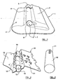
- the air-bag 1, as shown in Figure 1 is of generally rectangular form, and has a contoured under-surface 2.
- the under-surface 2 defines a substantially wedge-shaped projection 3, and also, adjacent one side of the wedge-shaped projection 3, a generally cylindrical projection 4.
- the cylindrical projection 4 is hollow and is provided primarily to receive a cylindrical gas generator as will be described.
- the access aperture 5 has a substantially circular region 6 provided in alignment with the longitudinal axis of the cylindrical projection 4, and a radially outwardly directed extension 7 in the form of a slot.
- a slit 8 is provided at the far end of the cylindrical projection 4 from the access aperture 5.
- the slit 8 seen most clearly in Figure 5 , extends transversely to the longitudinal axis of the cylindrical projection 4, and extends part way around the circumference of the cylindrical projection 4 and part way up one wall of the wedge-shaped projection 3.
- a mounting plate 10 (shown in Figure 2 ) is provided to facilitate mounting the air-bag 1 in position, for example in part of the squab of a vehicle seat.
- the mounting plate may be formed of metal or of plastic.
- the mounting plate 10 comprises a first substantially planar portion 11 configured, as will become clearer from the following description, to overly the under-surface of the wedge-shaped projection 3 discussed above.
- the planar portion 11 merges into an arcuate region 12 positioned to overly the cylindrical projection 4.
- a further terminal planar region 13 is provided to extend away from the arcuate region 12.
- One end of the arcuate region 12 is depressed downwardly from the mounting plate to form a depending strap 14 that extends beneath the arcuate region 12, thus defining, at one side edge of the mounting plate, an aperture 15.
- the aperture 15 is located to be co-aligned with the access aperture 5.
- an axially extending slot 16 is provided in the uppermost part of the arcuate region 12.
- a generally cylindrical gas generator 20 is provided as shown in Figure 3 , the gas generator having a radially extending stud 21 adjacent one end.
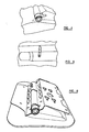
- the gas generator 20 may be inserted into the air-bag 1 by aligning the gas generator 20 so that the stud 21 is in alignment with the radial extension 7 of the access aperture 5.
- the cylindrical gas generator 20 may then be inserted into the air-bag with the end adjacent the stud 21 entering the aperture 5 first and with the stud 21 entering the air-bag through the radial extension 7.
- the gas generator 20 may be urged into the air-bag 1 through the access aperture 5, as shown in Figure 4 .
- the gas generator 20 may be inserted into the air-bag 1 until the stud 21 is aligned with the slit 8 provided in the uppermost part of the cylindrical projection 4. The gas generator 20 may then be rotated by about 90°, with the stud 21 passing through the slit 8, until the stud is substantially vertical.
- the stud, in the vertical position, is shown from above in Figure 5 , and projects through the slit 8.
- the mounting plate 10 may then be lowered onto the stud 21, with the stud 21 passing through the end of the slot 16 which is furthest from the aperture 15.
- the metal strap 14 will be lowered past the end of the gas generator 20.
- the mounting plate 10 may then be moved transversely so that the metal strap 14 is moved to a position where it engages a terminal part of the gas generator as shown in Figure 6 . During this movement the stud 21 will effectively move to the end of the slot 16 which is closest to the aperture 15.
- the entire air-bag may then be mounted in position on the mounting plate using a single nut on the stud 21.
- the combination of the nut and the stud 21 will serve to retain one end of the gas generator 20, and the engagement of the strap 14 of the support plate 10 with the other end of the gas generator 20 will retain the other end of the gas generator in position. With both ends of the gas generator being retained in position the entire air-bag is retained in position on the mounting plate 10.
- the mounting plate 10 may be secured to the framework of a seat squab by bolts or equivalent fastening passing through apertures in the mounting plate.
- the air-bag is provided with two integral vents.
- the first vent is formed by the radial extension 7 of the circular portion 6 of the aperture 5 through which the gas generator 20 is inserted into the air-bag, and the second vent is formed is formed by part of the slit 8 formed in the wall of the wedge shaped projection 3. Both of the integral vents are thus constituted by a pre-formed hole provided in the air-bag.
- FIG. 7 an alternate form of pelvic restraint cushion 30 is illustrated which, again, is in the form of an air-bag formed from a substantially rigid material, such as a plastics material.
- Figure 7 shows part of a pelvic restraint cushion 30, the pelvic restraint cushion 30 defining a generally cylindrical region 31 to receive a gas generator.
- the air-bag is formed using a blow-moulding technique. As the air-bag is blow-moulded, so a projection 32 is created which extends away from the interior of the air-bag, the uppermost part of the projection being in the form of a thin web or foil 33.
- the web or foil 33 forms a burst disc which will burst if gas pressure within the bag rises to a predetermined level.
- FIG 8 illustrates a further pelvic restraint cushion 40 which is very similar to the pelvic restraint cushion 30 described above with reference to Figure 7 .
- part of the material of the air-bag, in a specific area 41 is abraded away so that the area 41 forms a very thin foil or burst disc.
- the invention has been described with reference to embodiments formed of plastic.
- the invention also relates to air-bags made of metal.
- the vent may be stamped in the metal.
Landscapes
- Engineering & Computer Science (AREA)
- Mechanical Engineering (AREA)
- Aviation & Aerospace Engineering (AREA)
- Transportation (AREA)
- Air Bags (AREA)
- Seats For Vehicles (AREA)
- Packages (AREA)
Claims (7)
- Die Kombination eines aus im Wesentlichen starrem Material gebildeten Airbags und eines Gasgenerators, wobei der Air-bag mit einem integrierten, durch ein vorgeformtes Loch in dem Airbag gebildeten Luftdurchlass gebildet ist, dadurch gekennzeichnete dass das Loch zum Aufnehmen eines Teils des Gasgenerators beim Einsetzen des Teils des Gasgenerators in den Airbag dimensioniert ist,
- Die Kombination des Anspruchs 1, wobei der Gasgenerator die Form eines Zylinders aufweist mit einem sich seitlich erstreckenden Bolzen (21) nahe einem Ende, und wobei das Loch eine im wesentlichen kreisrunde Öffnung (6) umfasst, die zum Aufnehmen des Zylinders eingerichtet ist, mit einer radialen Erweiterung (7) der im Wesentlichen, kreisrunden Öffnung, die zum Aufnehmen des vorstehenden Bolzens (21) beim Einführen in den Airbag dimensioniert ist und den integrierten Luftdurchlass nach dem Einsetzen des Gasgenerators in den Airbag bildet.
- Die Kombination des Anspruchs 2, umfassend eine Befestigungsplatte, die einen Schlitz zum Aufnehmen des Bolzens an dem Gasgenerator aufweist, wobei die Befestigungsplatte einen Teil zum zusammenwirken mit einem Ende des Gasgenerators aufweist.
- Die Kombination des Anspruchs 3, wobei die Befestigungsplatte einen bogenförmigen Bereich aufweist, der zum Überlagern eines den Gasgenerator aufnehmenden zylindrischen Abschnitts des Airbags eingerichtet; ist, wobei der bogenförmige Bereich einen abhängige Streifen an einem Ende zum Definieren einer Öffnung aufweist, wobei die öffnung zum Aufnehmen eines von dem Bag vorstehenden Endbereichs des Gasgenerators dimensioniert ist, wobei der bogenförmige Bereich einen sich axial erstreckenden, an dem anderen Ende vorgesehenen Schlitz aufweist, wobei der Schlitz zum Aufnehmen des Bolzens an dem Gasgenerator dimensioniert ist,
- Die Kombination nach einem der vorangehenden Ansprüche, wobei der Airbag aus einem Kunststoffmaterial blasgeformt ist.
- Die Kombination nach einem der vorangehenden Ansprüche, wobei der Airbag aus einem Metall gefertigt ist.
- Die Kombination nach einem der vorangehenden Ansprüche, wobei der Airbag ein Beckengurtpolster ist.
Applications Claiming Priority (2)
| Application Number | Priority Date | Filing Date | Title |
|---|---|---|---|
| GB0415073A GB2415937B (en) | 2004-07-05 | 2004-07-05 | Improvements in or relating to an air-bag |
| PCT/SE2005/000906 WO2006004485A1 (en) | 2004-07-05 | 2005-06-15 | An air-bag |
Publications (2)
| Publication Number | Publication Date |
|---|---|
| EP1765644A1 EP1765644A1 (de) | 2007-03-28 |
| EP1765644B1 true EP1765644B1 (de) | 2008-05-21 |
Family
ID=32843616
Family Applications (1)
| Application Number | Title | Priority Date | Filing Date |
|---|---|---|---|
| EP05752730A Expired - Lifetime EP1765644B1 (de) | 2004-07-05 | 2005-06-15 | Airbag |
Country Status (6)
| Country | Link |
|---|---|
| EP (1) | EP1765644B1 (de) |
| JP (1) | JP4926052B2 (de) |
| AT (1) | ATE396087T1 (de) |
| DE (1) | DE602005007027D1 (de) |
| GB (1) | GB2415937B (de) |
| WO (1) | WO2006004485A1 (de) |
Families Citing this family (3)
| Publication number | Priority date | Publication date | Assignee | Title |
|---|---|---|---|---|
| JP5136531B2 (ja) * | 2009-09-29 | 2013-02-06 | 豊田合成株式会社 | 樹脂エアバッグ |
| JP5381752B2 (ja) * | 2009-09-29 | 2014-01-08 | 豊田合成株式会社 | 樹脂エアバッグ |
| US9994138B2 (en) | 2015-12-02 | 2018-06-12 | Ford Global Technologies, Llc | Seat with deployable plastic beam |
Family Cites Families (12)
| Publication number | Priority date | Publication date | Assignee | Title |
|---|---|---|---|---|
| JP3339099B2 (ja) * | 1993-04-12 | 2002-10-28 | タカタ株式会社 | 助手席用エアバッグ装置 |
| US5615914A (en) * | 1995-01-17 | 1997-04-01 | Olin Corporation | Inflatable metal bladders for automobile passenger protection |
| JPH1044188A (ja) * | 1996-08-06 | 1998-02-17 | Takata Kk | 樹脂製エアバッグの製造方法及び樹脂製エアバッグ |
| JPH1191425A (ja) * | 1997-09-19 | 1999-04-06 | Tokai Rika Co Ltd | 車両用シート |
| US6032978A (en) * | 1998-08-07 | 2000-03-07 | Abc Group Interior Systems | Inflatable knee bolster |
| US6213497B1 (en) * | 1998-08-07 | 2001-04-10 | Delphi Technologies, Inc. | Inflatable knee bolster |
| GB9904266D0 (en) * | 1999-02-24 | 1999-04-21 | Automotive Dev Specialists Ltd | Inflatable protection apparatus |
| GB2357466B (en) * | 1999-12-21 | 2003-04-02 | Autoliv Dev | Improvements in or relating to a vehicle seat |
| GB2373218B (en) * | 2001-03-13 | 2004-12-15 | Autoliv Dev | Improvements in or relating to a safety arrangement |
| FR2827521B1 (fr) * | 2001-07-17 | 2003-12-12 | Aerazur | Procede pour l'introduction, a l'interieur d'un sac de securite gonflable, de pieces mecaniques telles qu'un generateur de gaz, et sac de securite gonflable pour la mise-en-oeuvre de ce procede |
| WO2004011308A1 (ja) * | 2002-07-25 | 2004-02-05 | Autoliv Development Ab | 乗員拘束装置用インフレータバッグ及びその製造方法 |
| GB0222720D0 (en) * | 2002-10-01 | 2002-11-06 | Dalphimetal Ltd | Vehicle seat with a pelvis energy management device |
-
2004
- 2004-07-05 GB GB0415073A patent/GB2415937B/en not_active Expired - Fee Related
-
2005
- 2005-06-15 JP JP2007519153A patent/JP4926052B2/ja not_active Expired - Fee Related
- 2005-06-15 DE DE602005007027T patent/DE602005007027D1/de not_active Expired - Lifetime
- 2005-06-15 EP EP05752730A patent/EP1765644B1/de not_active Expired - Lifetime
- 2005-06-15 AT AT05752730T patent/ATE396087T1/de not_active IP Right Cessation
- 2005-06-15 WO PCT/SE2005/000906 patent/WO2006004485A1/en not_active Ceased
Also Published As
| Publication number | Publication date |
|---|---|
| DE602005007027D1 (en) | 2008-07-03 |
| EP1765644A1 (de) | 2007-03-28 |
| JP2008505003A (ja) | 2008-02-21 |
| GB0415073D0 (en) | 2004-08-04 |
| ATE396087T1 (de) | 2008-06-15 |
| GB2415937A (en) | 2006-01-11 |
| GB2415937B (en) | 2007-11-07 |
| JP4926052B2 (ja) | 2012-05-09 |
| WO2006004485A1 (en) | 2006-01-12 |
Similar Documents
| Publication | Publication Date | Title |
|---|---|---|
| EP1369314B1 (de) | Schutzeinrichtung für Insassen | |
| EP1486384B1 (de) | Kindersitz mit Airbag | |
| US8282126B2 (en) | Occupant restraint system | |
| EP2370296B1 (de) | Steuerungssystem für airbagentfaltung | |
| US7066487B2 (en) | Airbag with internal positioning panels for sequential deployment | |
| US6752454B2 (en) | Vehicle seat | |
| US20060043702A1 (en) | Dual chamber airbag | |
| CN101016041A (zh) | 车辆用空气安全带装置 | |
| US11247633B1 (en) | Occupant restraint system for a vehicle seat including an inflatable tensioning member for an airbag | |
| US5895069A (en) | Knee restraint means | |
| CN102887128A (zh) | 用于车辆的乘员保护系统及保护自动车辆的乘员的方法 | |
| US9975516B2 (en) | Occupant protection device for vehicle | |
| US11325555B2 (en) | Vehicle seat | |
| US10308205B2 (en) | Safety restraint system with an airbag having an inflatable pelvis restraint portion and related method | |
| US7032926B2 (en) | Inflatable safety device | |
| EP3521109A1 (de) | Seitenairbagvorrichtung | |
| US20060267323A1 (en) | Divided airbag system | |
| US9586554B1 (en) | B-pillar trim strap for structural rigidity during CSA deployment | |
| EP3400152B1 (de) | Seitenairbag mit innendiffusor | |
| US20140265274A1 (en) | Airbag module | |
| EP1925507A1 (de) | Rückhaltesystem für fahrzeuginsassen | |
| KR20090120026A (ko) | 차량의 에어백 | |
| CN105799633B (zh) | 具有设置在座部内的安全气囊模块的车辆座椅 | |
| CN114007908A (zh) | 用于车辆的乘员保护系统的腿部保护设备 | |
| WO2006004485A1 (en) | An air-bag |
Legal Events
| Date | Code | Title | Description |
|---|---|---|---|
| PUAI | Public reference made under article 153(3) epc to a published international application that has entered the european phase |
Free format text: ORIGINAL CODE: 0009012 |
|
| 17P | Request for examination filed |
Effective date: 20061211 |
|
| AK | Designated contracting states |
Kind code of ref document: A1 Designated state(s): AT BE BG CH CY CZ DE DK EE ES FI FR GB GR HU IE IS IT LI LT LU MC NL PL PT RO SE SI SK TR |
|
| 17Q | First examination report despatched |
Effective date: 20070531 |
|
| DAX | Request for extension of the european patent (deleted) | ||
| GRAP | Despatch of communication of intention to grant a patent |
Free format text: ORIGINAL CODE: EPIDOSNIGR1 |
|
| GRAS | Grant fee paid |
Free format text: ORIGINAL CODE: EPIDOSNIGR3 |
|
| RBV | Designated contracting states (corrected) |
Designated state(s): AT BE BG CH CY CZ DE DK EE ES FI FR GR HU IE IS IT LI LT LU MC NL PL PT RO SE SI SK TR |
|
| GRAA | (expected) grant |
Free format text: ORIGINAL CODE: 0009210 |
|
| AK | Designated contracting states |
Kind code of ref document: B1 Designated state(s): AT BE BG CH CY CZ DE DK EE ES FI FR GR HU IE IS IT LI LT LU MC NL PL PT RO SE SI SK TR |
|
| REG | Reference to a national code |
Ref country code: CH Ref legal event code: EP |
|
| REF | Corresponds to: |
Ref document number: 602005007027 Country of ref document: DE Date of ref document: 20080703 Kind code of ref document: P |
|
| REG | Reference to a national code |
Ref country code: IE Ref legal event code: FG4D |
|
| PG25 | Lapsed in a contracting state [announced via postgrant information from national office to epo] |
Ref country code: SI Free format text: LAPSE BECAUSE OF FAILURE TO SUBMIT A TRANSLATION OF THE DESCRIPTION OR TO PAY THE FEE WITHIN THE PRESCRIBED TIME-LIMIT Effective date: 20080521 |
|
| PG25 | Lapsed in a contracting state [announced via postgrant information from national office to epo] |
Ref country code: ES Free format text: LAPSE BECAUSE OF FAILURE TO SUBMIT A TRANSLATION OF THE DESCRIPTION OR TO PAY THE FEE WITHIN THE PRESCRIBED TIME-LIMIT Effective date: 20080901 Ref country code: FI Free format text: LAPSE BECAUSE OF FAILURE TO SUBMIT A TRANSLATION OF THE DESCRIPTION OR TO PAY THE FEE WITHIN THE PRESCRIBED TIME-LIMIT Effective date: 20080521 |
|
| NLV1 | Nl: lapsed or annulled due to failure to fulfill the requirements of art. 29p and 29m of the patents act | ||
| PG25 | Lapsed in a contracting state [announced via postgrant information from national office to epo] |
Ref country code: NL Free format text: LAPSE BECAUSE OF FAILURE TO SUBMIT A TRANSLATION OF THE DESCRIPTION OR TO PAY THE FEE WITHIN THE PRESCRIBED TIME-LIMIT Effective date: 20080521 Ref country code: AT Free format text: LAPSE BECAUSE OF FAILURE TO SUBMIT A TRANSLATION OF THE DESCRIPTION OR TO PAY THE FEE WITHIN THE PRESCRIBED TIME-LIMIT Effective date: 20080521 Ref country code: PL Free format text: LAPSE BECAUSE OF FAILURE TO SUBMIT A TRANSLATION OF THE DESCRIPTION OR TO PAY THE FEE WITHIN THE PRESCRIBED TIME-LIMIT Effective date: 20080521 |
|
| PG25 | Lapsed in a contracting state [announced via postgrant information from national office to epo] |
Ref country code: IS Free format text: LAPSE BECAUSE OF FAILURE TO SUBMIT A TRANSLATION OF THE DESCRIPTION OR TO PAY THE FEE WITHIN THE PRESCRIBED TIME-LIMIT Effective date: 20080921 |
|
| PG25 | Lapsed in a contracting state [announced via postgrant information from national office to epo] |
Ref country code: LT Free format text: LAPSE BECAUSE OF FAILURE TO SUBMIT A TRANSLATION OF THE DESCRIPTION OR TO PAY THE FEE WITHIN THE PRESCRIBED TIME-LIMIT Effective date: 20080521 Ref country code: CZ Free format text: LAPSE BECAUSE OF FAILURE TO SUBMIT A TRANSLATION OF THE DESCRIPTION OR TO PAY THE FEE WITHIN THE PRESCRIBED TIME-LIMIT Effective date: 20080521 Ref country code: SE Free format text: LAPSE BECAUSE OF FAILURE TO SUBMIT A TRANSLATION OF THE DESCRIPTION OR TO PAY THE FEE WITHIN THE PRESCRIBED TIME-LIMIT Effective date: 20080821 Ref country code: DK Free format text: LAPSE BECAUSE OF FAILURE TO SUBMIT A TRANSLATION OF THE DESCRIPTION OR TO PAY THE FEE WITHIN THE PRESCRIBED TIME-LIMIT Effective date: 20080521 Ref country code: MC Free format text: LAPSE BECAUSE OF NON-PAYMENT OF DUE FEES Effective date: 20080630 |
|
| PG25 | Lapsed in a contracting state [announced via postgrant information from national office to epo] |
Ref country code: SK Free format text: LAPSE BECAUSE OF FAILURE TO SUBMIT A TRANSLATION OF THE DESCRIPTION OR TO PAY THE FEE WITHIN THE PRESCRIBED TIME-LIMIT Effective date: 20080521 Ref country code: PT Free format text: LAPSE BECAUSE OF FAILURE TO SUBMIT A TRANSLATION OF THE DESCRIPTION OR TO PAY THE FEE WITHIN THE PRESCRIBED TIME-LIMIT Effective date: 20081021 Ref country code: BE Free format text: LAPSE BECAUSE OF FAILURE TO SUBMIT A TRANSLATION OF THE DESCRIPTION OR TO PAY THE FEE WITHIN THE PRESCRIBED TIME-LIMIT Effective date: 20080521 Ref country code: RO Free format text: LAPSE BECAUSE OF FAILURE TO SUBMIT A TRANSLATION OF THE DESCRIPTION OR TO PAY THE FEE WITHIN THE PRESCRIBED TIME-LIMIT Effective date: 20080521 |
|
| PLBE | No opposition filed within time limit |
Free format text: ORIGINAL CODE: 0009261 |
|
| STAA | Information on the status of an ep patent application or granted ep patent |
Free format text: STATUS: NO OPPOSITION FILED WITHIN TIME LIMIT |
|
| 26N | No opposition filed |
Effective date: 20090224 |
|
| PG25 | Lapsed in a contracting state [announced via postgrant information from national office to epo] |
Ref country code: BG Free format text: LAPSE BECAUSE OF FAILURE TO SUBMIT A TRANSLATION OF THE DESCRIPTION OR TO PAY THE FEE WITHIN THE PRESCRIBED TIME-LIMIT Effective date: 20080821 Ref country code: IE Free format text: LAPSE BECAUSE OF NON-PAYMENT OF DUE FEES Effective date: 20080615 Ref country code: EE Free format text: LAPSE BECAUSE OF FAILURE TO SUBMIT A TRANSLATION OF THE DESCRIPTION OR TO PAY THE FEE WITHIN THE PRESCRIBED TIME-LIMIT Effective date: 20080521 |
|
| PG25 | Lapsed in a contracting state [announced via postgrant information from national office to epo] |
Ref country code: IT Free format text: LAPSE BECAUSE OF FAILURE TO SUBMIT A TRANSLATION OF THE DESCRIPTION OR TO PAY THE FEE WITHIN THE PRESCRIBED TIME-LIMIT Effective date: 20080521 |
|
| REG | Reference to a national code |
Ref country code: CH Ref legal event code: PL |
|
| PG25 | Lapsed in a contracting state [announced via postgrant information from national office to epo] |
Ref country code: LI Free format text: LAPSE BECAUSE OF NON-PAYMENT OF DUE FEES Effective date: 20090630 Ref country code: CH Free format text: LAPSE BECAUSE OF NON-PAYMENT OF DUE FEES Effective date: 20090630 |
|
| PG25 | Lapsed in a contracting state [announced via postgrant information from national office to epo] |
Ref country code: CY Free format text: LAPSE BECAUSE OF FAILURE TO SUBMIT A TRANSLATION OF THE DESCRIPTION OR TO PAY THE FEE WITHIN THE PRESCRIBED TIME-LIMIT Effective date: 20080521 Ref country code: HU Free format text: LAPSE BECAUSE OF FAILURE TO SUBMIT A TRANSLATION OF THE DESCRIPTION OR TO PAY THE FEE WITHIN THE PRESCRIBED TIME-LIMIT Effective date: 20081122 Ref country code: LU Free format text: LAPSE BECAUSE OF NON-PAYMENT OF DUE FEES Effective date: 20080615 |
|
| PG25 | Lapsed in a contracting state [announced via postgrant information from national office to epo] |
Ref country code: TR Free format text: LAPSE BECAUSE OF FAILURE TO SUBMIT A TRANSLATION OF THE DESCRIPTION OR TO PAY THE FEE WITHIN THE PRESCRIBED TIME-LIMIT Effective date: 20080521 |
|
| PG25 | Lapsed in a contracting state [announced via postgrant information from national office to epo] |
Ref country code: GR Free format text: LAPSE BECAUSE OF FAILURE TO SUBMIT A TRANSLATION OF THE DESCRIPTION OR TO PAY THE FEE WITHIN THE PRESCRIBED TIME-LIMIT Effective date: 20080822 |
|
| PGFP | Annual fee paid to national office [announced via postgrant information from national office to epo] |
Ref country code: FR Payment date: 20110517 Year of fee payment: 7 |
|
| REG | Reference to a national code |
Ref country code: FR Ref legal event code: ST Effective date: 20130228 |
|
| PG25 | Lapsed in a contracting state [announced via postgrant information from national office to epo] |
Ref country code: FR Free format text: LAPSE BECAUSE OF NON-PAYMENT OF DUE FEES Effective date: 20120702 |
|
| PGFP | Annual fee paid to national office [announced via postgrant information from national office to epo] |
Ref country code: DE Payment date: 20150413 Year of fee payment: 11 |
|
| REG | Reference to a national code |
Ref country code: DE Ref legal event code: R119 Ref document number: 602005007027 Country of ref document: DE |
|
| PG25 | Lapsed in a contracting state [announced via postgrant information from national office to epo] |
Ref country code: DE Free format text: LAPSE BECAUSE OF NON-PAYMENT OF DUE FEES Effective date: 20170103 |