EP1767307A1 - Dispositif de contrôle de soudage à l'arc - Google Patents
Dispositif de contrôle de soudage à l'arc Download PDFInfo
- Publication number
- EP1767307A1 EP1767307A1 EP05753406A EP05753406A EP1767307A1 EP 1767307 A1 EP1767307 A1 EP 1767307A1 EP 05753406 A EP05753406 A EP 05753406A EP 05753406 A EP05753406 A EP 05753406A EP 1767307 A1 EP1767307 A1 EP 1767307A1
- Authority
- EP
- European Patent Office
- Prior art keywords
- control unit
- arc welding
- welding control
- heat radiating
- set forth
- Prior art date
- Legal status (The legal status is an assumption and is not a legal conclusion. Google has not performed a legal analysis and makes no representation as to the accuracy of the status listed.)
- Withdrawn
Links
Images



Classifications
-
- H—ELECTRICITY
- H05—ELECTRIC TECHNIQUES NOT OTHERWISE PROVIDED FOR
- H05K—PRINTED CIRCUITS; CASINGS OR CONSTRUCTIONAL DETAILS OF ELECTRIC APPARATUS; MANUFACTURE OF ASSEMBLAGES OF ELECTRICAL COMPONENTS
- H05K7/00—Constructional details common to different types of electric apparatus
- H05K7/20—Modifications to facilitate cooling, ventilating, or heating
- H05K7/2089—Modifications to facilitate cooling, ventilating, or heating for power electronics, e.g. for inverters for controlling motor
- H05K7/20909—Forced ventilation, e.g. on heat dissipaters coupled to components
-
- B—PERFORMING OPERATIONS; TRANSPORTING
- B23—MACHINE TOOLS; METAL-WORKING NOT OTHERWISE PROVIDED FOR
- B23K—SOLDERING OR UNSOLDERING; WELDING; CLADDING OR PLATING BY SOLDERING OR WELDING; CUTTING BY APPLYING HEAT LOCALLY, e.g. FLAME CUTTING; WORKING BY LASER BEAM
- B23K9/00—Arc welding or cutting
- B23K9/32—Accessories
- B23K9/325—Devices for supplying or evacuating shielding gas
Definitions
- the invention relates to a cooling structure provided in an arc welding control unit.
- Fig. 8 is a perspective view of the structure of a conventional arc welding control unit, in particular, a perspective view of a box body part arranged on the outer side of the control unit.
- reference character 101 designates a box body provided in the arc welding control unit, 102 an air intake/exhaust opening, 103 a fan, 104 a heat sink, and 105 a main semiconductor, respectively.
- various components and wires which are used to enforce arc welding are not connected directly with the description of the invention and thus the description thereof is omitted here.
- the description of the circuit configurations of the control unit is also omitted here for the same reason.
- the control unit As a method for cooling the main semiconductor (for example, a switching element such as a power transistor) which gives off intense heat, there is employed a method in which the heat sink is intensively cooled and the air is applied to the whole of the main semiconductor to thereby cool the main semiconductor: that is, the control unit is structured such that the air existing in the outside of the control unit is taken into or discharged from the whole of the inside of the control unit for cooling.
- the main semiconductor for example, a switching element such as a power transistor
- the fan 103 is operated to take in the air from the outside and the air is applied to an integrated body formed by contacting the heat sink 104 with the main semiconductor 5, while the air heated is exhausted from the air intake/exhaust opening 102 to thereby discharge the heat of the control unit.
- Patent literature 1 JP Hei-8-214549 publication (Fig. 1)
- an arc welding control unit having a heat radiating unit built in the box body thereof for discharging the air heated by a heat generating first electrical element to the outside, in which the heat radiating unit has a tunnel-type shape including an outer peripheral portion for defining a cavity portion allowing the air to pass therethrough.
- the heat radiating unit used in the arc welding control unit of the invention has a substantially cuboid shape including a side surface portion and a top surface portion for defining the cavity portion, and the two side end portions of the cavity portion are formed as openings through which the air is allowed to pass through. Further, the openings of the two side end portions of the heat radiating unit are disposed to face the inside surface of the box body, and the heat generating first electrical element is used in at least part of the outer peripheral portion defining the cavity portion.
- the heat generating electrical element used in the arc welding control unit of the invention includes a heat sink having a heat radiating fin, the heat radiating fin is disposed so as to be exposed to the inside of the cavity portion through which the air is allowed to pass, and, on one of the two heat radiating unit openings, there is provided a fan for forcing the air within the cavity portion to flow.
- the heat radiating unit has two or more rows of cavity portions, while each of the two or more rows of cavity has a fan.
- provision of the box body for cooling can prevent dust, welding fumes and the like from accumulating on or adhering to the conductive portions of the inside of the equipment, which can greatly improve the maintenance of the equipment as well as can secure the reliability of the equipment.
- Fig. 5 is a circuit diagram of the circuit configurations of the arc welding control unit according to the present embodiment.
- a portion thereof shown by a one-dot chained line and given reference character 20 is a primary side inverter circuit
- 28 designates a power transistor used as an inverter (switching means) in the primary side inverter circuit
- 21 stands for a main transformer
- a portion shown by a two-dot chained line and given reference character 22 is a secondary side main circuit
- 23 designates a dc reactor
- 24 stands for a control circuit.
- Power supplied from a commercial power supply 25 is rectified by a primary rectify diode 26 in the primary side inverter circuit 20, and the thus rectified power is smoothed and converted to a direct current by a primary smoothing capacitor 27. And, the voltage and current are inverter controlled by the power transistor 28 so as to provide the voltage and current of a desired high frequency. Further, the voltage is raised from the primary side to the secondary side by the main transformer 21, the current is converted again to a direct current by a secondary side rectify diode, positive and negative voltages are respectively output, and arcs are discharged between a wire 30 and a base metal 29 for enforcing arc welding.
- the dc reactor 23 in the secondary side circuit cuts high frequency components to improve the quality of the arc welding.
- the control circuit 24 is used to control the output voltage and current in the primary side inverter circuit 20 and in the secondary side circuit in order to stabilize the quality of the arc welding.
- a heat radiating unit 1 carries thereon the primary side inverter circuit 20, secondary side main circuit 22 and the like previously described with reference to Fig. 5, and is disposed in the form of a unit in the arc welding control unit.
- the heat radiating unit 1 has a heat radiating mechanism in order to cool the power transistor 28 and the like which give off intense heat.
- Fig. 1 is a perspective view of a heat radiating unit used in an arc welding control unit according to the present embodiment, when viewed from the backward and rightward direction of the heat radiating unit.
- reference character 1 designates a heat radiating unit; and, 4a and 4b stand for the side surface portion and the top surface portion of the heat radiating unit 1 respectively, while they form the outer peripheral portion of the heat radiating unit 1.
- 28 designates the power transistor in the primary side inverter circuit shown in the circuit diagram of Fig. 5.
- 10a stands for an opening formed in the end portion of the heat radiating unit 1
- 8 designates fans respectively arranged in the opening 8.
- the respective surfaces of the side surface portion 4a and top surface portion 4b are formed in such a manner that the power transistor 28 and the like are connected to flat plates such as thin metal plates which are the base materials of the portions 4a and 4b; and, owing to the thus formed surfaces, the heat radiating unit 1 has a tunnel structure including a cavity portion. That is, the heat radiating unit 1 has a tunnel structure in which the electrical element generating intense heat is used as part of the outer peripheral portion thereof defined by the top surface portion and side surface portion thereof, the cavity portion 3 is defined by the outer peripheral portion; and, the heat is discharged in such a manner that the cavity portion and the outside are isolated from each other.
- the heat radiating unit 1 as shown in Fig. 6, is built into the box body 2 to thereby provide a welding control unit and, in the present embodiment, the heat radiating unit 1 is disposed in such a manner that the portion thereof including the fan 8 provides the rear surface portion of the welding control unit.
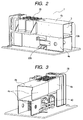
- Fig. 2 is a perspective view of the same heat radiating unit 1 used in the arc welding control unit according to the present embodiment as shown in Fig. 1, when viewed from the forward and leftward direction thereof
- reference character 10b designates an opening formed on the opposite side to the fan 8 of the two side end portions of the heat radiating unit 1
- 3 stands for a cavity portion which is defined by the side surface portion 4a and top surface portion 4b of the heat radiating unit 1.
- the heat radiating unit 1 has a tunnel structure including a cavity portion defined by the side surface portion 4a and top surface portion 4b and includes two openings respectively formed in the two end portions thereof, with a fan provided on one of the two openings.
- Fig. 3 similarly to the above figures, is a perspective view of the heat radiating unit 1, when viewed from the forward and rightward direction thereof
- 40 designates a switching element which, although not shown in the circuit diagram of Fig. 5, is used in a secondary side circuit and gives off intense heat.
- Fig. 4 similarly to Fig. 3, is a perspective view of the heat radiating unit 1, when viewed from the forward and rightward direction thereof, and, for easy understanding of the inside thereof, it is shown in such a manner that the middle portion thereof is cut.
- 6 designates heat sinks and 7 stands for heat radiating fins.
- the heat sinks 6 are respectively included in the respective electrical elements of the power transistor 28, secondary side switching element 40 and secondary side rectify diode 22; and, the portions thereof including the heat radiating fins 7 are exposed to the inside of the heat radiating unit 1 having a tunnel structure, that is, to the portion of the cavity portion 3 through which the air is allowed to flow.
- the heat radiating unit 1 has cavity portions respectively in the two upper and lower stage structure; in each stage structure, there are provided two or more rows of cavities separated from one another with partitions between them; and, the respective cavity portions 3 are formed to allow the air to flow therethrough.
- the heat radiating unit 1 As described above, the heat radiating unit 1 according to the present embodiment, as shown in Fig. 1, has a substantially cuboid shape, in which the fan 8 is arranged in the opening 10a formed in the front surface thereof and is used as an air intake opening, whereas the air is exhausted from the opposite opening 10b.
- the heat radiating unit 1 there is mounted, of the electrical elements constituting the circuits of the present welding control unit, the electrical element that gives off specially intense heat; and, the heat radiating fin portions of the heat sinks 6 are exposed to the cavity portions 3 through which the air flows, whereby the heat can be discharged out of the control unit with high efficiency.
- the two or more heat radiating fins 7 should be disposed to be substantially parallel with the direction of flow of the air flowing through the cavities 3, thereby being able to prevent the flow of the air from stagnating.
- the heat radiating unit 1 since the heat radiating unit 1 has a two-stage (upper-and-lower-stage) structure, for example, the electrical elements giving off intense heat can be cooled in the cavity portions exclusively arranged for cooling purpose, thereby preventing them from interfering with the promotion of the cooling of the remaining electrical elements.
- the side surface portion 4a and top surface portion 4b defining the outer peripheral surface of the heat radiating unit 1 are respectively formed as flat surfaces capable of shutting off the air, the flow of the air between the cavity portions 3 defined by these flat surfaces and the outside is cut off. Further dust, welding fumes and the like can be prevented from entering the conductive portions of the interior portions of the tunnel structure of the heat radiating unit 1.
- the heat radiating unit 1 is built into the box body 2 to thereby provide an arc welding control unit.
- the box body 2 is arranged such that it includes two air flow holes 2a previously formed in the mutually facing surfaces thereof respectively, so that the openings 10a and 10b of the heat radiating unit 1 can be respectively engaged with the air flow holes 2a. That is, the heat radiating unit 1 is disposed such that the openings 10a and 10b of the two side end portions thereof respectively face the inside surfaces of the mutually facing surfaces of the box body 2.
- the fans 8 provided in the heat radiating unit 1 are arranged to face the inside surface of the rear surface of the arc welding control unit, the air is sucked in from the outside, and heat is discharged to the outside from the air flow hole 2a formed in the front surface of the control unit. And, as described above, in the inside of the box body 2, due to the tunnel structure of the heat radiating unit 1, heat transmission can be cut off between the cavity portions of the interior portion of the unit 1 and the outside, thereby being able to cool the electrical elements efficiently.
- the fans 8 are mounted on the heat radiating unit 1.
- they may also be mounted in the air flow holes 2a of the box body 2 or may be interposed between the inside surface of the box body 2 and the opening 10a of the heat radiating unit 1. Each of them has no ill influence on the effect of the present embodiment.
- the heat radiating unit 1 is formed to have a two upper and lower stage structure
- the structure is not limited to the two-stage structure, but two or more lines or rows of cavity portions may also be provided in the horizontal and/or vertical direction, which makes it possible to discharge heat with more efficiency.
- the cavity portions may be used respectively to discharge the heat of different electrical elements, or one of more cavity portions may be used to discharge the heat of two or more electrical elements.
- the shape of the heat radiating unit 1 is not limited to a substantially cuboid shape but it may be other shape such as a cylindrical shape, provided that it is capable of forming a tunnel structure.
- the heat sink 8 and box body 9 are shut off from the air existing in the inside of the equipment, dust, welding fumes and the like can be prevented from accumulating on or adhering to the conductive portions of the inside of the equipment. This not only can improve the maintenance of the equipment greatly but also can secure the reliability of the equipment as well.
- the dc reactor 23 shown in Fig. 5 in the inside of the heat radiating unit 1 having a tunnel structure, there may be provided the dc reactor 23 shown in Fig. 5.
- the dc reactor 23 which is one of heat generating sources, is arranged in the lower-stage cavity portion of the heat radiating unit 1 having a two stage structure and is exposed to a different row of cavity portions from those in the upper stage, the cavity portions in the lower stage can be shut off from the remaining rows of cavity portions, thereby being able to cool the electrical elements with high efficiency.
- the dc reactor for an arc welding control unit is impregnated with varnish, which raises no problem relating to the accumulation of dust and the like.
- the heat sinks 7 and heat radiating unit 1 are shut off from the air existing in the inside of the welding control unit, dust, welding fumes and the like can be prevented from accumulating on and adhering to the conductive portions of the inside of the equipment. Thanks to this, the maintenance of the equipment can be improved greatly and the reliability of the equipment can also be secured.
- An arc welding control unit can prevent dust, welding fumes and the like from accumulating on or adhering to the conductive portions of the equipment to thereby be able not only to improve the maintenance of the equipment greatly but also to secure the reliability of the equipment as well. Therefore, the present arc welding control unit is industrially useful. Also, the invention not only can be usefully applied to an arc welding control unit but also can be usefully applied to a wide range of apparatus which have built-in electrical elements generating intense heat and require cooling them.
Landscapes
- Engineering & Computer Science (AREA)
- Physics & Mathematics (AREA)
- Microelectronics & Electronic Packaging (AREA)
- Plasma & Fusion (AREA)
- Mechanical Engineering (AREA)
- Thermal Sciences (AREA)
- Arc Welding Control (AREA)
- Cooling Or The Like Of Electrical Apparatus (AREA)
- Generation Of Surge Voltage And Current (AREA)
Applications Claiming Priority (2)
| Application Number | Priority Date | Filing Date | Title |
|---|---|---|---|
| JP2004186083A JP4155234B2 (ja) | 2004-06-24 | 2004-06-24 | アーク溶接制御装置 |
| PCT/JP2005/011350 WO2006001273A1 (fr) | 2004-06-24 | 2005-06-21 | Dispositif de contrôle de soudage à l'arc |
Publications (2)
| Publication Number | Publication Date |
|---|---|
| EP1767307A1 true EP1767307A1 (fr) | 2007-03-28 |
| EP1767307A4 EP1767307A4 (fr) | 2009-03-25 |
Family
ID=35775058
Family Applications (1)
| Application Number | Title | Priority Date | Filing Date |
|---|---|---|---|
| EP05753406A Withdrawn EP1767307A4 (fr) | 2004-06-24 | 2005-06-21 | Dispositif de contrôle de soudage à l'arc |
Country Status (5)
| Country | Link |
|---|---|
| US (1) | US20070034617A1 (fr) |
| EP (1) | EP1767307A4 (fr) |
| JP (1) | JP4155234B2 (fr) |
| CN (1) | CN1826204A (fr) |
| WO (1) | WO2006001273A1 (fr) |
Cited By (2)
| Publication number | Priority date | Publication date | Assignee | Title |
|---|---|---|---|---|
| EP2338628B1 (fr) | 2009-07-10 | 2016-01-06 | Panasonic Intellectual Property Management Co., Ltd. | Procédé de commande de soudage à l'arc et dispositif de soudage à l'arc |
| EP3099153A1 (fr) * | 2015-05-26 | 2016-11-30 | Hitachi, Ltd. | Appareil d'alimentation électrique |
Families Citing this family (16)
| Publication number | Priority date | Publication date | Assignee | Title |
|---|---|---|---|---|
| JP5056093B2 (ja) * | 2007-03-19 | 2012-10-24 | パナソニック株式会社 | 電気機器 |
| WO2009098854A1 (fr) * | 2008-02-06 | 2009-08-13 | Panasonic Corporation | Dispositif électrique |
| JP2010099692A (ja) * | 2008-10-23 | 2010-05-06 | Daihen Corp | アーク溶接制御装置 |
| JP2011188671A (ja) * | 2010-03-10 | 2011-09-22 | Daihen Corp | 電源装置 |
| JP5596389B2 (ja) * | 2010-03-29 | 2014-09-24 | 株式会社ダイヘン | 電源装置 |
| CN102189358B (zh) * | 2010-03-10 | 2015-09-30 | 株式会社大亨 | 焊接电源 |
| EP2364807B1 (fr) * | 2010-03-10 | 2013-05-08 | Daihen Corporation | Appareil d'alimentation électrique incluant un ventilateur pour le refroidissement de l'air |
| CN102223056A (zh) * | 2011-06-22 | 2011-10-19 | 中国科学院电工研究所 | 一种高频高压电源结构 |
| AT512446B1 (de) * | 2012-01-24 | 2013-11-15 | Fronius Int Gmbh | Outdorgehäuse mit wechselrichter und gebläse |
| CN102862491B (zh) * | 2012-09-28 | 2014-09-03 | 引峰新能源科技(上海)有限公司 | 紧凑型燃料电池电源系统 |
| CN107000102B (zh) * | 2014-11-11 | 2020-03-24 | 松下知识产权经营株式会社 | 焊接装置 |
| DE102017206775A1 (de) * | 2017-04-21 | 2018-10-25 | Lenze Automation Gmbh | Elektrisches Steuergerät |
| KR101867473B1 (ko) * | 2017-05-12 | 2018-07-03 | 주식회사 포웰 | 인버터형 ac 아크 용접기 |
| US10925194B2 (en) * | 2018-02-28 | 2021-02-16 | Illinois Tool Works Inc. | Dual chamber wind tunnels for a welding-type power source |
| KR102125815B1 (ko) * | 2018-07-03 | 2020-06-23 | 주식회사 포웰 | 소형용접기용 집중방열구조체 |
| US11925008B2 (en) * | 2018-10-31 | 2024-03-05 | Illinois Tool Works Inc. | Methods and apparatus for multi-directional fan |
Family Cites Families (9)
| Publication number | Priority date | Publication date | Assignee | Title |
|---|---|---|---|---|
| JPS5414927Y2 (fr) * | 1973-07-02 | 1979-06-18 | ||
| JPS5977578U (ja) * | 1982-11-16 | 1984-05-25 | 株式会社三社電機製作所 | 小型溶接機の冷却装置 |
| JPH0899182A (ja) * | 1994-09-29 | 1996-04-16 | Miyachi Technos Corp | インバータ式溶接電源ユニット |
| TW283274B (fr) * | 1994-11-08 | 1996-08-11 | Sansha Denki Seisakusho Co Ltd | |
| US5642260A (en) * | 1996-01-16 | 1997-06-24 | Illinois Tool Works Inc. | Welding power supply housing |
| US6489591B1 (en) * | 2000-04-10 | 2002-12-03 | Illinois Tool Works Inc. | Cooling air circuits for welding machine |
| US6888099B1 (en) * | 2003-03-06 | 2005-05-03 | Illinois Tool Works Inc. | Wind tunnel for a welding power supply housing |
| US6989509B2 (en) * | 2003-03-17 | 2006-01-24 | Lincoln Global, Inc. | Self-contained integrated welder/generator and compressor |
| US7005608B2 (en) * | 2003-08-07 | 2006-02-28 | Lincoln Global, Inc. | Cooling system for arc welding |
-
2004
- 2004-06-24 JP JP2004186083A patent/JP4155234B2/ja not_active Expired - Fee Related
-
2005
- 2005-06-21 WO PCT/JP2005/011350 patent/WO2006001273A1/fr not_active Ceased
- 2005-06-21 US US10/568,990 patent/US20070034617A1/en not_active Abandoned
- 2005-06-21 CN CNA2005800007207A patent/CN1826204A/zh active Pending
- 2005-06-21 EP EP05753406A patent/EP1767307A4/fr not_active Withdrawn
Cited By (3)
| Publication number | Priority date | Publication date | Assignee | Title |
|---|---|---|---|---|
| EP2338628B1 (fr) | 2009-07-10 | 2016-01-06 | Panasonic Intellectual Property Management Co., Ltd. | Procédé de commande de soudage à l'arc et dispositif de soudage à l'arc |
| EP3099153A1 (fr) * | 2015-05-26 | 2016-11-30 | Hitachi, Ltd. | Appareil d'alimentation électrique |
| US9750125B2 (en) | 2015-05-26 | 2017-08-29 | Hitachi, Ltd. | Power supply apparatus |
Also Published As
| Publication number | Publication date |
|---|---|
| JP2006007255A (ja) | 2006-01-12 |
| US20070034617A1 (en) | 2007-02-15 |
| WO2006001273A1 (fr) | 2006-01-05 |
| JP4155234B2 (ja) | 2008-09-24 |
| EP1767307A4 (fr) | 2009-03-25 |
| CN1826204A (zh) | 2006-08-30 |
Similar Documents
| Publication | Publication Date | Title |
|---|---|---|
| US20070034617A1 (en) | Arc welding control device | |
| US5831240A (en) | Power supply apparatus | |
| US6665183B1 (en) | Power supply apparatus | |
| EP3160029B1 (fr) | Onduleur | |
| EP0951208B1 (fr) | Unité amplificatrice pour asservissement | |
| JP5704760B2 (ja) | 急速充電器 | |
| KR101541181B1 (ko) | 전기자동차용 전력 변환 장치 | |
| US11277017B2 (en) | Charger configured to charge battery pack of power tool | |
| JP4525268B2 (ja) | 電力変換装置の冷却装置 | |
| JP4093479B2 (ja) | 電源装置 | |
| WO2012147189A1 (fr) | Dispositif de conversion de courant | |
| US11780024B2 (en) | Welding power supply having a cooling device | |
| EP3462592B1 (fr) | Module onduleur, onduleur et système de refroidissement d'onduleur | |
| US9801314B2 (en) | Power source apparatus | |
| JP2021016225A (ja) | 電子機器および電子制御装置 | |
| JP2003259657A (ja) | 電力変換装置 | |
| JP2013085399A (ja) | 急速充電器 | |
| KR200494468Y1 (ko) | 모듈형 냉각장치를 이용한 방열 시스템 | |
| EP3407478B1 (fr) | Dispositif de conversion de puissance | |
| CN100488691C (zh) | 焊接装置 | |
| CN118511666A (zh) | 电力转换装置 | |
| CN118511667A (zh) | 电力转换装置 | |
| CN213185904U (zh) | 一种风冷大功率整流器功率模组 | |
| JP2007165423A (ja) | 電子機器装置 | |
| CN107000102A (zh) | 焊接装置 |
Legal Events
| Date | Code | Title | Description |
|---|---|---|---|
| PUAI | Public reference made under article 153(3) epc to a published international application that has entered the european phase |
Free format text: ORIGINAL CODE: 0009012 |
|
| 17P | Request for examination filed |
Effective date: 20060220 |
|
| AK | Designated contracting states |
Kind code of ref document: A1 Designated state(s): AT BE BG CH CY CZ DE DK EE ES FI FR GB GR HU IE IS IT LI LT LU MC NL PL PT RO SE SI SK TR |
|
| DAX | Request for extension of the european patent (deleted) | ||
| RAP1 | Party data changed (applicant data changed or rights of an application transferred) |
Owner name: PANASONIC CORPORATION |
|
| A4 | Supplementary search report drawn up and despatched |
Effective date: 20090224 |
|
| STAA | Information on the status of an ep patent application or granted ep patent |
Free format text: STATUS: THE APPLICATION IS DEEMED TO BE WITHDRAWN |
|
| 18D | Application deemed to be withdrawn |
Effective date: 20090526 |