EP1767313A2 - Outil de sertissage - Google Patents
Outil de sertissage Download PDFInfo
- Publication number
- EP1767313A2 EP1767313A2 EP06118572A EP06118572A EP1767313A2 EP 1767313 A2 EP1767313 A2 EP 1767313A2 EP 06118572 A EP06118572 A EP 06118572A EP 06118572 A EP06118572 A EP 06118572A EP 1767313 A2 EP1767313 A2 EP 1767313A2
- Authority
- EP
- European Patent Office
- Prior art keywords
- pressing
- contour
- jaw
- jaw halves
- halves
- Prior art date
- Legal status (The legal status is an assumption and is not a legal conclusion. Google has not performed a legal analysis and makes no representation as to the accuracy of the status listed.)
- Granted
Links
Images


Classifications
-
- B—PERFORMING OPERATIONS; TRANSPORTING
- B21—MECHANICAL METAL-WORKING WITHOUT ESSENTIALLY REMOVING MATERIAL; PUNCHING METAL
- B21D—WORKING OR PROCESSING OF SHEET METAL OR METAL TUBES, RODS OR PROFILES WITHOUT ESSENTIALLY REMOVING MATERIAL; PUNCHING METAL
- B21D39/00—Application of procedures in order to connect objects or parts, e.g. coating with sheet metal otherwise than by plating; Tube expanders
- B21D39/04—Application of procedures in order to connect objects or parts, e.g. coating with sheet metal otherwise than by plating; Tube expanders of tubes with tubes; of tubes with rods
-
- B—PERFORMING OPERATIONS; TRANSPORTING
- B25—HAND TOOLS; PORTABLE POWER-DRIVEN TOOLS; MANIPULATORS
- B25B—TOOLS OR BENCH DEVICES NOT OTHERWISE PROVIDED FOR, FOR FASTENING, CONNECTING, DISENGAGING, OR HOLDING
- B25B27/00—Hand tools, specially adapted for fitting together or separating parts or objects whether or not involving some deformation, not otherwise provided for
- B25B27/02—Hand tools, specially adapted for fitting together or separating parts or objects whether or not involving some deformation, not otherwise provided for for connecting objects by press fit or detaching same
- B25B27/10—Hand tools, specially adapted for fitting together or separating parts or objects whether or not involving some deformation, not otherwise provided for for connecting objects by press fit or detaching same inserting fittings into hoses
Definitions
- the present invention relates to a pressing tool having two pressing jaw halves extending in the longitudinal direction from a rear end to a front end, which are hinged together and can be brought from an open position to a closed position, wherein the pressing jaw halves each have an inlet contour at the rear end, wherein the inlet contours cooperate with a movable part of a pressing contour such that the movable part of the pressing contour, as it is displaced in the longitudinal direction towards the front end of the pressing jaw halves, moves along the inlet contours and pushes them apart to the pressing jaw halves from the open position to the closed position bring.
- the press tools serve to enclose a specific area of the fitting with a press jaw after the pipe end has been inserted into the fitting. Subsequently, to create the cold connection, the enclosed areas, for example a bead and the parts adjacent to the bead, of the fitting are pressed together by closing the press jaw so that the fitting and the pipe deform in the area of the press jaw.
- a press jaw with press contour with two extending in the longitudinal direction from a rear end to a front end die jaw halves is for example from the EP 1 095 739 B1 known.
- the two die jaw halves are hingedly connected to each other, as a rule over transverse to the longitudinal direction extending bridge parts, at one end of which a die jaw half is rotatably mounted and at the other end the other die jaw half is rotatably mounted.
- the two pressing jaw halves form a pressing jaw which can be brought from an open position into a closed position in order to non-detachably connect the fitting to the pipe end by cold deformation.
- each an inlet contour is provided, wherein the two inlet contours in the open position of the pressing jaw touch.
- the inlet contours interact with the pressing contour, the movable part of which generally has rollers, in such a way that the moving part of the pressing contour, when displaced longitudinally towards the front end of the pressing jaw halves, moves along the inlet contours and pushes them apart.
- a non-moving part of the pressing contour is firmly connected to the bridge parts. The farther the rollers press the inlet contours of the two pressing jaw halves apart, the more the press jaw closes up to the closed position of the pressing jaw.
- the DE 42 40 427 C1 also known for large diameters pressing tools in which the press jaw is formed from a ring of hingedly interconnected chain links.
- the individual members of such a press chain can be unfolded to accommodate the fitting.
- the chain links for example by means of a separate electro-hydraulic locking device, closed again or moved together to close the press jaw. Due to the elaborate technology is a such press tool but relatively expensive.
- the folding of the press chain around the section of the fitting to be pressed is relatively time-consuming.
- each pressing jaw half has at least one recess and at least one projection in the region of its inlet contour, the projection of one pressing jaw half lying opposite the depression of the other pressing jaw half.
- the two pressing jaw halves are identical parts, ie components of the same shape and dimensions.
- a pressing tool can be used, which has almost the same structure as the pressing tools, which are used for nominal widths up to 54 mm, so a relatively simple design press tool.
- a possibility is created to increase the opening angle of the press jaw by the rear ends of the pressing jaw halves, where the inlet contours are provided, in the open position of the pressing tool even further to each other can be moved.
- the profile of the inlet contours, along which the movable part of the pressing contour moves along in order to bring about closure of the pressing jaw does not change with respect to the known pressing tool.
- the same pressing contours can still be used for the pressing tool according to the invention, despite an altered rear end of the pressing jaw halves and an associated larger opening angle, in order to actuate the pressing jaw.
- the inlet contours so the outer surface of the rear pressing jaw end, remain unchanged from the prior art and at the same time allows the two rear ends of the pressing jaw halves dive into each other or intermesh. The deeper the depressions are provided at the rear end of the pressing jaw halves, the larger becomes the opening angle of the pressing jaw at the same inlet contour.
- the recess and / or the projection is in each case elongated and extends in particular in the longitudinal direction of the pressing jaw halves.
- the width, height and / or length of the recess corresponds to the width, height or length of the respectively opposite projection.
- the dimensions of the projection should be chosen so that the projection on the one hand easily fits into the opposite depression, without requiring, for example, a greater effort would be necessary, and on the other hand, the projection is so wide and so stable that the pressing contour can slide along it and transmit a large force.
- the pressing tool engage in the open position of the pressing jaw halves of the projection and the recess, each opposite, completely into each other. In this way, at the same time an optimal lateral guidance of the pressing jaw halves is achieved at the rear end of the pressing jaw halves in the open position with the press jaw open.
- each pressing jaw half preferably has the same number of depressions and / or projections. It has proved to be advantageous if each pressing jaw half each has a recess and a projection or two recesses and two projections.
- the first variant is particularly easy to manufacture and the latter variant enables optimized power transmission from the pressing contour to the inlet contours.
- the movable part of the pressing contour is formed such that it comes into contact only with the projections of the pressing jaw halves. But there are also more complex pressing contours conceivable, immerse the moving part in the wells and thus the Force can transmit not only on the projections, but also on the depressions on the die halves.
- the movable part of the pressing contour rollers which can roll along the projections.
- Fig. 1 shows a section through a conventional pressing tool 1 with a pressing jaw, which is suitable for press connections, in which the nominal diameter of the pipe end, which is guided into the fitting, can be up to 54 mm.
- the pressing tool has two longitudinally extending from a rear end to a front end pressing jaw halves 2, which are hinged together, in such a way that each of the pressing jaw halves 2 is rotatably mounted on bridge parts 3 via bolts 4, wherein the bridge parts 3, from in which only the rear is shown in Fig. 1, represent the connection of the pressing jaw halves 2.
- the conventional pressing tool 1 or the pressing jaw halves 2 can be moved from an open position in which the pressing jaw is maximally open into a closed position in which the pressing jaw is closed and a pressing force can be exerted on a fitting.
- At the rear end of the two pressing jaw halves 2 each have an inlet contour 5 is provided, which cooperate with a movable part of a pressing contour 6, in particular with the rollers 7 of the pressing contour 6, as follows.
- the inlet contours 5 of the respective pressing jaw halves 2 touch each other in a section and thereby limit the maximum opening angle of the press jaw.
- the movable part of the pressing contour 6 is now displaced in the longitudinal direction towards the front end of the pressing jaw halves 2, the non-movable part of the pressing contour 6 being fixedly connected to the bridge parts 3, then the rollers 7 move along the Inlet contours 5 and push them apart. Since the pressing jaw halves 2 are connected to one another in an articulated manner via the bridge parts 3 and the bolts 4, the pressing jaw is correspondingly closed until finally the closed position is reached.
- a fitting 8 is shown schematically, are inserted into the tubes of a nominal diameter greater than 54 mm. It becomes clear that despite maximum opening of the press jaw, the fitting 8 can not be inserted between the press jaw halves 2 because its diameter is too large.
- Fig. 2 now shows a sectional view of a first embodiment of a pressing tool 1 according to the present invention.
- the pressing tool is constructed similar to the pressing tool 1 described above with reference to FIG.
- two pressing jaw halves 2 are articulated to one another via bridge parts 3 and bolts 4 and have at their front end a pressing jaw and at their rear end inlet contours 5 which interact with a movable part of a pressing contour 6 via rollers 7.
- FIG. 2 It can be clearly seen from FIG. 2 that a fitting 8 of the same size, as shown in FIG. 1, can be introduced without difficulty into the press jaw of the press tool according to the invention, since in the open position, compared to the prior art, a larger maximum opening angle is reached.
- each pressing jaw half 2 in the region of its inlet contour. 5 Recesses 9 and projections 10, wherein the projections 10 of a pressing jaw half opposite the recesses 9 of the other die jaw half.
- Fig. 3 a three-dimensional view of the pressing jaw of the embodiment of Fig. 2 is shown.
- the opposite recesses 9 and projections 10 can be clearly seen in the region of the inlet contours 5.
- two depressions 9 and two projections 10 are provided in the region of each inlet contour 5.
- the recesses 9 and the projections 10 are each elongated and extend in the longitudinal direction of the pressing jaw halves 2.
- the width, height and length of the recesses 9 correspond exactly to the width, the height and the length of the respective opposite projections 10. In this way In the open position of the pressing jaw halves 2, which is shown in FIG. 3, the recesses 9 and the projections 10, which lie opposite one another, can completely engage one another.
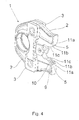
- the closed position in which the maximum pressing action is achieved, is now shown in FIG. 4 for the above-described embodiment according to the invention.
- the closed position is achieved in that the rollers 7 (not shown) are moved along the inlet contours 5 in the direction of the front end of the pressing jaw halves 2, whereby the pressing jaw halves 2 pressed apart in the region of its rear end and in the region of its front end, where in the present case the press jaw is provided to be compressed.
- the rollers 7 of the pressing contour 6 on the outer surface of the rear end of the pressing jaw halves 2, which here forms a portion of the inlet contour 5, are moved along.
- the inlet contour 5 is formed by different sections, namely first by a flat portion 11a, in which no depressions are provided, followed by a portion formed by the projections 10 11b, to which finally an end portion 11c adjacent, which also no depressions having. In the region of the portion 11 b formed by the projections 10 grooves are milled, which form the recesses 9.
- the pressing force is thus on the rollers 7 of the pressing contour 6 in the sections 11 a and 11 c of the inlet contours 5 on the Whole width of the pressing jaw halves 2 transferred to this, whereas in the section 11 b, the power transmission takes place only on the projections 10.
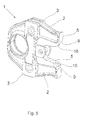
- FIG. Fig. 5 shows the pressing jaw, so the two articulated pressing jaw halves 2, in the same view as Fig. 4, that is in three-dimensional view in the closed position.
Landscapes
- Engineering & Computer Science (AREA)
- Mechanical Engineering (AREA)
- Press Drives And Press Lines (AREA)
- Scissors And Nippers (AREA)
- Measurement Of The Respiration, Hearing Ability, Form, And Blood Characteristics Of Living Organisms (AREA)
- Perforating, Stamping-Out Or Severing By Means Other Than Cutting (AREA)
- Apparatuses For Bulk Treatment Of Fruits And Vegetables And Apparatuses For Preparing Feeds (AREA)
- Mutual Connection Of Rods And Tubes (AREA)
- Non-Disconnectible Joints And Screw-Threaded Joints (AREA)
Applications Claiming Priority (1)
| Application Number | Priority Date | Filing Date | Title |
|---|---|---|---|
| DE102005046333A DE102005046333B3 (de) | 2005-09-27 | 2005-09-27 | Presswerkzeug |
Publications (3)
| Publication Number | Publication Date |
|---|---|
| EP1767313A2 true EP1767313A2 (fr) | 2007-03-28 |
| EP1767313A3 EP1767313A3 (fr) | 2008-04-23 |
| EP1767313B1 EP1767313B1 (fr) | 2010-01-27 |
Family
ID=37055722
Family Applications (1)
| Application Number | Title | Priority Date | Filing Date |
|---|---|---|---|
| EP06118572A Active EP1767313B1 (fr) | 2005-09-27 | 2006-08-08 | Outil de sertissage |
Country Status (5)
| Country | Link |
|---|---|
| US (1) | US7484398B2 (fr) |
| EP (1) | EP1767313B1 (fr) |
| AT (1) | ATE456428T1 (fr) |
| DE (2) | DE102005046333B3 (fr) |
| DK (1) | DK1767313T3 (fr) |
Families Citing this family (6)
| Publication number | Priority date | Publication date | Assignee | Title |
|---|---|---|---|---|
| DE102007006929A1 (de) * | 2007-02-05 | 2008-08-07 | REMS-WERK Christian Föll und Söhne GmbH & Co KG | Presszange |
| DE102007040895A1 (de) | 2007-08-24 | 2009-02-26 | REMS-WERK Christian Föll und Söhne GmbH & Co KG | Presszange zum radialen Verpressen von Rohren, Rohrstücken und dergleichen |
| DE102012100357B4 (de) * | 2012-01-17 | 2014-05-22 | Viega Gmbh & Co. Kg | Lösbare Werkzeugbackenhälfte |
| DE102015107302B4 (de) | 2015-05-11 | 2021-07-08 | Viega Technology Gmbh & Co. Kg | Presswerkzeug und Verfahren zum Verbinden von Werkstücken mit Kraftmessung |
| US11398719B2 (en) | 2019-04-30 | 2022-07-26 | Eaton Intelligent Power Limited | Press fit condulet devices, assemblies systems and methods for electrical raceway fabrication |
| US11996683B2 (en) | 2020-10-19 | 2024-05-28 | Eaton Intelligent Power Limited | Compressible condulet devices, assemblies, systems and methods for electrical raceway fabrication |
Citations (1)
| Publication number | Priority date | Publication date | Assignee | Title |
|---|---|---|---|---|
| DE10354307A1 (de) | 2003-02-07 | 2004-08-19 | Gustav Klauke Gmbh | Verpressbackenpaar |
Family Cites Families (60)
| Publication number | Priority date | Publication date | Assignee | Title |
|---|---|---|---|---|
| US2022043A (en) * | 1933-12-05 | 1935-11-26 | Charles A Knuutila | Flower stemming machine |
| US2953970A (en) * | 1957-09-26 | 1960-09-27 | Indiana General Corp | Mount for optical system component |
| US3057233A (en) * | 1960-12-21 | 1962-10-09 | Bodendieck Tool Company | Lever hot stick for compressing sleeves and connectors |
| US3372443A (en) * | 1967-02-16 | 1968-03-12 | Scovill Manufacturing Co | Magnetic fastening means |
| US3727658A (en) * | 1971-09-22 | 1973-04-17 | Instranetics Inc | Receiver for surgical implements |
| US3952334A (en) * | 1974-11-29 | 1976-04-27 | General Atomic Company | Biocompatible carbon prosthetic devices |
| US3986493A (en) * | 1975-07-28 | 1976-10-19 | Hendren Iii William Hardy | Electromagnetic bougienage method |
| DE2717607C3 (de) * | 1977-04-20 | 1981-06-25 | Coloplast A/S, Espergaerde | Magnetverschlußstopfen für einen Darmausgang |
| US4109504A (en) * | 1977-04-22 | 1978-08-29 | Reiner Rommel | Crimping tool for producing solderless permanent electrical connections |
| US4210132A (en) * | 1978-07-26 | 1980-07-01 | The Kendall Company | Artificial sphincter |
| US4258705A (en) * | 1978-09-15 | 1981-03-31 | Coloplast A/S | Magnetic system for use in sealing body openings |
| JPS583624Y2 (ja) * | 1979-09-26 | 1983-01-21 | 橋本 修二 | 錆付きナットの切断機 |
| SU1022703A1 (ru) * | 1979-12-20 | 1983-06-15 | Всесоюзный научно-исследовательский и испытательный институт медицинской техники | Хирургический аппарат дл наложени компрессионных швов |
| NL8403174A (nl) * | 1984-10-17 | 1986-05-16 | Franciscus Jacobus Maria De Vr | Implanteerbare afsluitinrichting. |
| CN1007847B (zh) * | 1984-12-24 | 1990-05-02 | 住友特殊金属株式会社 | 制造具有改进耐蚀性磁铁的方法 |
| JPH0624551B2 (ja) * | 1986-02-24 | 1994-04-06 | 名糖産業株式会社 | 括約機能を有する磁性人工肛門 |
| JPH0723871Y2 (ja) * | 1987-07-24 | 1995-05-31 | 富士電機株式会社 | 電磁接触器 |
| US4809713A (en) * | 1987-10-28 | 1989-03-07 | Joseph Grayzel | Catheter with magnetic fixation |
| US4935080A (en) * | 1988-01-29 | 1990-06-19 | Kollmorgen Corporation | Protection and bonding of neodymium-boron-iron magnets used in the formation of magnet assemblies |
| JP2520450B2 (ja) * | 1988-06-02 | 1996-07-31 | 信越化学工業株式会社 | 耐食性希土類磁石の製造方法 |
| US4899744A (en) * | 1988-12-15 | 1990-02-13 | Tatsuo Fujitsuka | Apparatus for anastomosing digestive tract |
| JPH02310395A (ja) * | 1989-05-26 | 1990-12-26 | Johoku Riken Kogyo:Kk | ネオジウム―鉄―ボロン系焼結磁石の防食方法 |
| GB2249319B (en) * | 1990-10-04 | 1994-11-30 | Hitachi Metals Ltd | R-TM-B permanent magnet member having improved corrosion resistance and method of producing same |
| US5138864A (en) * | 1990-12-28 | 1992-08-18 | Ripley Company, Inc. | Crimping tool |
| US5197649A (en) * | 1991-10-29 | 1993-03-30 | The Trustees Of Columbia University In The City Of New York | Gastrointestinal endoscoptic stapler |
| DE9207951U1 (de) * | 1992-06-12 | 1992-12-03 | Dental-Labor Hartmut Stemmann, 2000 Hamburg | Vorrichtung zum Positionieren eines Magneten in einer Zahnprothese |
| US5330486A (en) * | 1992-07-29 | 1994-07-19 | Wilk Peter J | Laparoscopic or endoscopic anastomosis technique and associated instruments |
| DE4244718C2 (de) * | 1992-08-27 | 1998-12-17 | Dental Labor Hartmut Stemmann | Magnetanordnung für therapeutische Zwecke |
| DE4240427C1 (de) * | 1992-12-02 | 1994-01-20 | Novopress Gmbh | Preßwerkzeug |
| GB9425578D0 (en) * | 1994-12-19 | 1995-02-15 | Connolly John G | redial treatment of urinary incontinence |
| US5507629A (en) * | 1994-06-17 | 1996-04-16 | Jarvik; Robert | Artificial hearts with permanent magnet bearings |
| US5595562A (en) * | 1994-11-10 | 1997-01-21 | Research Corporation Technologies, Inc. | Magnetic enteral gastrostomy |
| DE4446504C1 (de) * | 1994-12-25 | 1996-03-28 | Rothenberger Werkzeuge Masch | Preßwerkzeug zum radialen Verpressen von Werkstücken |
| US5695504A (en) * | 1995-02-24 | 1997-12-09 | Heartport, Inc. | Devices and methods for performing a vascular anastomosis |
| US5690656A (en) * | 1995-06-27 | 1997-11-25 | Cook Incorporated | Method and apparatus for creating abdominal visceral anastomoses |
| US6068637A (en) * | 1995-10-03 | 2000-05-30 | Cedar Sinai Medical Center | Method and devices for performing vascular anastomosis |
| US5702412A (en) * | 1995-10-03 | 1997-12-30 | Cedars-Sinai Medical Center | Method and devices for performing vascular anastomosis |
| IL151563A0 (en) * | 1995-10-13 | 2003-04-10 | Transvascular Inc | A longitudinal compression apparatus for compressing tissue |
| DE19543312C2 (de) * | 1995-11-03 | 1997-10-23 | Rothenberger Werkzeuge Masch | Preßvorrichtung zum radialen Verpressen von Leitungsverbindern |
| US6579311B1 (en) * | 1996-02-02 | 2003-06-17 | Transvascular, Inc. | Method for interstitial transvascular intervention |
| DE29602240U1 (de) * | 1996-02-09 | 1997-06-19 | Novopress GmbH Pressen und Presswerkzeuge & Co KG, 41460 Neuss | Preßgerät |
| US5830224A (en) * | 1996-03-15 | 1998-11-03 | Beth Israel Deaconess Medical Center | Catheter apparatus and methodology for generating a fistula on-demand between closely associated blood vessels at a pre-chosen anatomic site in-vivo |
| US5904147A (en) * | 1996-08-16 | 1999-05-18 | University Of Massachusetts | Intravascular catheter and method of controlling hemorrhage during minimally invasive surgery |
| US6565581B1 (en) * | 1996-09-16 | 2003-05-20 | Origin Medsystems, Inc. | Apparatus and method for performing an anastomosis |
| EP1011458A2 (fr) * | 1996-11-08 | 2000-06-28 | Russell A. Houser | Pontage par greffe percutanee et systeme de fixation |
| US6026814A (en) * | 1997-03-06 | 2000-02-22 | Scimed Life Systems, Inc. | System and method for percutaneous coronary artery bypass |
| US5895404A (en) * | 1997-09-29 | 1999-04-20 | Ruiz; Carlos E. | Apparatus and methods for percutaneously forming a passageway between adjacent vessels or portions of a vessel |
| US6074416A (en) * | 1997-10-09 | 2000-06-13 | St. Jude Medical Cardiovascular Group, Inc. | Wire connector structures for tubular grafts |
| US6056743A (en) * | 1997-11-04 | 2000-05-02 | Scimed Life Systems, Inc. | Percutaneous myocardial revascularization device and method |
| US6352543B1 (en) * | 2000-04-29 | 2002-03-05 | Ventrica, Inc. | Methods for forming anastomoses using magnetic force |
| US6220126B1 (en) * | 1998-07-31 | 2001-04-24 | Alberto G. Domenge | Hand tool having pivoted handles |
| US6113612A (en) * | 1998-11-06 | 2000-09-05 | St. Jude Medical Cardiovascular Group, Inc. | Medical anastomosis apparatus |
| US6173715B1 (en) * | 1999-03-01 | 2001-01-16 | Lucent Medical Systems, Inc. | Magnetic anatomical marker and method of use |
| US6428550B1 (en) * | 1999-05-18 | 2002-08-06 | Cardica, Inc. | Sutureless closure and deployment system for connecting blood vessels |
| US6702828B2 (en) * | 1999-09-01 | 2004-03-09 | Converge Medical, Inc. | Anastomosis system |
| DE50006944D1 (de) * | 1999-10-26 | 2004-08-05 | Ridge Tool Ag Balzers | Presswerkzeug und Verfahren zum kaltumformenden Verbinden von Werkstücken |
| US6606786B2 (en) * | 1999-11-15 | 2003-08-19 | Peter G. Mangone, Jr. | Device for forming an enclosure |
| DE10029761C1 (de) * | 2000-06-16 | 2001-10-31 | Mapress Gmbh & Co Kg | Verfahren zur Herstellung einer Rohrpressverbindung |
| US20030065345A1 (en) * | 2001-09-28 | 2003-04-03 | Kevin Weadock | Anastomosis devices and methods for treating anastomotic sites |
| US6971179B2 (en) * | 2002-09-27 | 2005-12-06 | Electroline Corporation | Cutting tool |
-
2005
- 2005-09-27 DE DE102005046333A patent/DE102005046333B3/de not_active Expired - Fee Related
-
2006
- 2006-08-08 DK DK06118572.4T patent/DK1767313T3/da active
- 2006-08-08 EP EP06118572A patent/EP1767313B1/fr active Active
- 2006-08-08 AT AT06118572T patent/ATE456428T1/de active
- 2006-08-08 DE DE502006006029T patent/DE502006006029D1/de active Active
- 2006-09-14 US US11/531,908 patent/US7484398B2/en active Active
Patent Citations (1)
| Publication number | Priority date | Publication date | Assignee | Title |
|---|---|---|---|---|
| DE10354307A1 (de) | 2003-02-07 | 2004-08-19 | Gustav Klauke Gmbh | Verpressbackenpaar |
Also Published As
| Publication number | Publication date |
|---|---|
| ATE456428T1 (de) | 2010-02-15 |
| DE102005046333B3 (de) | 2006-10-19 |
| DE502006006029D1 (de) | 2010-03-18 |
| DK1767313T3 (da) | 2010-05-25 |
| EP1767313B1 (fr) | 2010-01-27 |
| EP1767313A3 (fr) | 2008-04-23 |
| US7484398B2 (en) | 2009-02-03 |
| US20070068217A1 (en) | 2007-03-29 |
Similar Documents
| Publication | Publication Date | Title |
|---|---|---|
| EP0531897B1 (fr) | Outil de pressage pour sertir un objet pressé cylindrique, ou un objet ayant une section cylindrique sur un profilé cylindrique, notamment une conduite | |
| EP1649981B1 (fr) | Pince de sertissage | |
| EP1201371B1 (fr) | Outil de sertissage | |
| EP1463902B1 (fr) | Dispositif a raccords multiples | |
| EP3012923B1 (fr) | Pince de pression | |
| EP3012924B1 (fr) | Pince de pression | |
| EP3849749B1 (fr) | Outil de pressage | |
| WO2014009083A1 (fr) | Outil de sertissage d'embouts | |
| EP1941975A2 (fr) | Pince de serrage destinée au serrage d'outils | |
| EP3718180A1 (fr) | Mâchoires de sertissage ainsi que pince de sertissage avec deux mâchoires de pince | |
| DE4039435C1 (fr) | ||
| EP1591176A1 (fr) | Outil de sertissage de pièces | |
| EP3557094A1 (fr) | Maillon de fermeture à chaînes | |
| EP2601895B1 (fr) | Instrument médical | |
| EP1767313B1 (fr) | Outil de sertissage | |
| EP2522464B1 (fr) | Mordache et procédé de fabrication d'un emmanchement par pressage | |
| DE202008010080U1 (de) | Schiebeelement zur Übertragung einer Schiebekraft auf ein Rohranschlusselement und Verbindungswerkzeug | |
| EP1531016A1 (fr) | Outil de presse | |
| EP0383863A1 (fr) | Presse radiale pour pieces sensiblement cylindriques. | |
| EP3153279B1 (fr) | Outil formé à la manière d'une pince d'écartement | |
| DE102007040895A1 (de) | Presszange zum radialen Verpressen von Rohren, Rohrstücken und dergleichen | |
| EP1649948B1 (fr) | Outil de sertissage | |
| WO2007110160A1 (fr) | Maillon de chaîne indéformable | |
| DE10358553B3 (de) | Zange, insbesondere Ösenzange | |
| DE19730053C1 (de) | Vorrichtung zum Aufweiten der Enden rohrförmiger Werkstücke |
Legal Events
| Date | Code | Title | Description |
|---|---|---|---|
| PUAI | Public reference made under article 153(3) epc to a published international application that has entered the european phase |
Free format text: ORIGINAL CODE: 0009012 |
|
| AK | Designated contracting states |
Kind code of ref document: A2 Designated state(s): AT BE BG CH CY CZ DE DK EE ES FI FR GB GR HU IE IS IT LI LT LU LV MC NL PL PT RO SE SI SK TR |
|
| AX | Request for extension of the european patent |
Extension state: AL BA HR MK YU |
|
| PUAL | Search report despatched |
Free format text: ORIGINAL CODE: 0009013 |
|
| AK | Designated contracting states |
Kind code of ref document: A3 Designated state(s): AT BE BG CH CY CZ DE DK EE ES FI FR GB GR HU IE IS IT LI LT LU LV MC NL PL PT RO SE SI SK TR |
|
| AX | Request for extension of the european patent |
Extension state: AL BA HR MK RS |
|
| 17P | Request for examination filed |
Effective date: 20080528 |
|
| AKX | Designation fees paid |
Designated state(s): AT BE BG CH CY CZ DE DK EE ES FI FR GB GR HU IE IS IT LI LT LU LV MC NL PL PT RO SE SI SK TR |
|
| GRAP | Despatch of communication of intention to grant a patent |
Free format text: ORIGINAL CODE: EPIDOSNIGR1 |
|
| GRAS | Grant fee paid |
Free format text: ORIGINAL CODE: EPIDOSNIGR3 |
|
| GRAA | (expected) grant |
Free format text: ORIGINAL CODE: 0009210 |
|
| AK | Designated contracting states |
Kind code of ref document: B1 Designated state(s): AT BE BG CH CY CZ DE DK EE ES FI FR GB GR HU IE IS IT LI LT LU LV MC NL PL PT RO SE SI SK TR |
|
| REG | Reference to a national code |
Ref country code: GB Ref legal event code: FG4D Free format text: NOT ENGLISH |
|
| REG | Reference to a national code |
Ref country code: CH Ref legal event code: NV Representative=s name: TROESCH SCHEIDEGGER WERNER AG Ref country code: CH Ref legal event code: EP |
|
| REG | Reference to a national code |
Ref country code: SE Ref legal event code: TRGR |
|
| REG | Reference to a national code |
Ref country code: IE Ref legal event code: FG4D |
|
| REF | Corresponds to: |
Ref document number: 502006006029 Country of ref document: DE Date of ref document: 20100318 Kind code of ref document: P |
|
| REG | Reference to a national code |
Ref country code: NL Ref legal event code: T3 |
|
| REG | Reference to a national code |
Ref country code: DK Ref legal event code: T3 |
|
| LTIE | Lt: invalidation of european patent or patent extension |
Effective date: 20100127 |
|
| PG25 | Lapsed in a contracting state [announced via postgrant information from national office to epo] |
Ref country code: PT Free format text: LAPSE BECAUSE OF FAILURE TO SUBMIT A TRANSLATION OF THE DESCRIPTION OR TO PAY THE FEE WITHIN THE PRESCRIBED TIME-LIMIT Effective date: 20100527 Ref country code: LT Free format text: LAPSE BECAUSE OF FAILURE TO SUBMIT A TRANSLATION OF THE DESCRIPTION OR TO PAY THE FEE WITHIN THE PRESCRIBED TIME-LIMIT Effective date: 20100127 Ref country code: IS Free format text: LAPSE BECAUSE OF FAILURE TO SUBMIT A TRANSLATION OF THE DESCRIPTION OR TO PAY THE FEE WITHIN THE PRESCRIBED TIME-LIMIT Effective date: 20100527 Ref country code: ES Free format text: LAPSE BECAUSE OF FAILURE TO SUBMIT A TRANSLATION OF THE DESCRIPTION OR TO PAY THE FEE WITHIN THE PRESCRIBED TIME-LIMIT Effective date: 20100508 |
|
| REG | Reference to a national code |
Ref country code: IE Ref legal event code: FD4D |
|
| PG25 | Lapsed in a contracting state [announced via postgrant information from national office to epo] |
Ref country code: SI Free format text: LAPSE BECAUSE OF FAILURE TO SUBMIT A TRANSLATION OF THE DESCRIPTION OR TO PAY THE FEE WITHIN THE PRESCRIBED TIME-LIMIT Effective date: 20100127 Ref country code: PL Free format text: LAPSE BECAUSE OF FAILURE TO SUBMIT A TRANSLATION OF THE DESCRIPTION OR TO PAY THE FEE WITHIN THE PRESCRIBED TIME-LIMIT Effective date: 20100127 Ref country code: LV Free format text: LAPSE BECAUSE OF FAILURE TO SUBMIT A TRANSLATION OF THE DESCRIPTION OR TO PAY THE FEE WITHIN THE PRESCRIBED TIME-LIMIT Effective date: 20100127 Ref country code: FI Free format text: LAPSE BECAUSE OF FAILURE TO SUBMIT A TRANSLATION OF THE DESCRIPTION OR TO PAY THE FEE WITHIN THE PRESCRIBED TIME-LIMIT Effective date: 20100127 |
|
| PG25 | Lapsed in a contracting state [announced via postgrant information from national office to epo] |
Ref country code: RO Free format text: LAPSE BECAUSE OF FAILURE TO SUBMIT A TRANSLATION OF THE DESCRIPTION OR TO PAY THE FEE WITHIN THE PRESCRIBED TIME-LIMIT Effective date: 20100127 Ref country code: IE Free format text: LAPSE BECAUSE OF FAILURE TO SUBMIT A TRANSLATION OF THE DESCRIPTION OR TO PAY THE FEE WITHIN THE PRESCRIBED TIME-LIMIT Effective date: 20100127 Ref country code: GR Free format text: LAPSE BECAUSE OF FAILURE TO SUBMIT A TRANSLATION OF THE DESCRIPTION OR TO PAY THE FEE WITHIN THE PRESCRIBED TIME-LIMIT Effective date: 20100428 Ref country code: EE Free format text: LAPSE BECAUSE OF FAILURE TO SUBMIT A TRANSLATION OF THE DESCRIPTION OR TO PAY THE FEE WITHIN THE PRESCRIBED TIME-LIMIT Effective date: 20100127 Ref country code: CY Free format text: LAPSE BECAUSE OF FAILURE TO SUBMIT A TRANSLATION OF THE DESCRIPTION OR TO PAY THE FEE WITHIN THE PRESCRIBED TIME-LIMIT Effective date: 20100127 |
|
| PG25 | Lapsed in a contracting state [announced via postgrant information from national office to epo] |
Ref country code: SK Free format text: LAPSE BECAUSE OF FAILURE TO SUBMIT A TRANSLATION OF THE DESCRIPTION OR TO PAY THE FEE WITHIN THE PRESCRIBED TIME-LIMIT Effective date: 20100127 Ref country code: CZ Free format text: LAPSE BECAUSE OF FAILURE TO SUBMIT A TRANSLATION OF THE DESCRIPTION OR TO PAY THE FEE WITHIN THE PRESCRIBED TIME-LIMIT Effective date: 20100127 Ref country code: BG Free format text: LAPSE BECAUSE OF FAILURE TO SUBMIT A TRANSLATION OF THE DESCRIPTION OR TO PAY THE FEE WITHIN THE PRESCRIBED TIME-LIMIT Effective date: 20100427 |
|
| PLBE | No opposition filed within time limit |
Free format text: ORIGINAL CODE: 0009261 |
|
| STAA | Information on the status of an ep patent application or granted ep patent |
Free format text: STATUS: NO OPPOSITION FILED WITHIN TIME LIMIT |
|
| 26N | No opposition filed |
Effective date: 20101028 |
|
| PG25 | Lapsed in a contracting state [announced via postgrant information from national office to epo] |
Ref country code: MC Free format text: LAPSE BECAUSE OF NON-PAYMENT OF DUE FEES Effective date: 20100831 |
|
| GBPC | Gb: european patent ceased through non-payment of renewal fee |
Effective date: 20100808 |
|
| PG25 | Lapsed in a contracting state [announced via postgrant information from national office to epo] |
Ref country code: GB Free format text: LAPSE BECAUSE OF NON-PAYMENT OF DUE FEES Effective date: 20100808 |
|
| PG25 | Lapsed in a contracting state [announced via postgrant information from national office to epo] |
Ref country code: HU Free format text: LAPSE BECAUSE OF FAILURE TO SUBMIT A TRANSLATION OF THE DESCRIPTION OR TO PAY THE FEE WITHIN THE PRESCRIBED TIME-LIMIT Effective date: 20100728 Ref country code: LU Free format text: LAPSE BECAUSE OF NON-PAYMENT OF DUE FEES Effective date: 20100808 |
|
| PG25 | Lapsed in a contracting state [announced via postgrant information from national office to epo] |
Ref country code: TR Free format text: LAPSE BECAUSE OF FAILURE TO SUBMIT A TRANSLATION OF THE DESCRIPTION OR TO PAY THE FEE WITHIN THE PRESCRIBED TIME-LIMIT Effective date: 20100127 |
|
| REG | Reference to a national code |
Ref country code: FR Ref legal event code: PLFP Year of fee payment: 11 |
|
| REG | Reference to a national code |
Ref country code: DE Ref legal event code: R082 Ref document number: 502006006029 Country of ref document: DE Representative=s name: COHAUSZ & FLORACK PATENT- UND RECHTSANWAELTE P, DE Ref country code: DE Ref legal event code: R081 Ref document number: 502006006029 Country of ref document: DE Owner name: VIEGA TECHNOLOGY GMBH & CO. KG, DE Free format text: FORMER OWNER: VIEGA GMBH & CO. KG, 57439 ATTENDORN, DE |
|
| REG | Reference to a national code |
Ref country code: AT Ref legal event code: PC Ref document number: 456428 Country of ref document: AT Kind code of ref document: T Owner name: VIEGA TECHNOLOGY GMBH & CO. KG, DE Effective date: 20170512 |
|
| REG | Reference to a national code |
Ref country code: NL Ref legal event code: PD Owner name: VIEGA TECHNOLOGY GMBH & CO. KG; DE Free format text: DETAILS ASSIGNMENT: CHANGE OF OWNER(S), ASSIGNMENT; FORMER OWNER NAME: VIEGA GMBH & CO. KG. Effective date: 20170412 |
|
| REG | Reference to a national code |
Ref country code: FR Ref legal event code: PLFP Year of fee payment: 12 |
|
| REG | Reference to a national code |
Ref country code: FR Ref legal event code: TP Owner name: VIEGA TECHNOLOGY GMBH & CO. KG, DE Effective date: 20171013 |
|
| REG | Reference to a national code |
Ref country code: CH Ref legal event code: PUE Owner name: VIEGA TECHNOLOGY GMBH AND CO. KG, DE Free format text: FORMER OWNER: VIEGA GMBH AND CO. KG, DE |
|
| REG | Reference to a national code |
Ref country code: FR Ref legal event code: PLFP Year of fee payment: 13 |
|
| PGFP | Annual fee paid to national office [announced via postgrant information from national office to epo] |
Ref country code: FR Payment date: 20200821 Year of fee payment: 15 Ref country code: DK Payment date: 20200824 Year of fee payment: 15 |
|
| PGFP | Annual fee paid to national office [announced via postgrant information from national office to epo] |
Ref country code: SE Payment date: 20200820 Year of fee payment: 15 Ref country code: BE Payment date: 20200824 Year of fee payment: 15 |
|
| REG | Reference to a national code |
Ref country code: DK Ref legal event code: EBP Effective date: 20210831 |
|
| REG | Reference to a national code |
Ref country code: SE Ref legal event code: EUG |
|
| REG | Reference to a national code |
Ref country code: BE Ref legal event code: MM Effective date: 20210831 |
|
| PG25 | Lapsed in a contracting state [announced via postgrant information from national office to epo] |
Ref country code: SE Free format text: LAPSE BECAUSE OF NON-PAYMENT OF DUE FEES Effective date: 20210809 |
|
| PG25 | Lapsed in a contracting state [announced via postgrant information from national office to epo] |
Ref country code: FR Free format text: LAPSE BECAUSE OF NON-PAYMENT OF DUE FEES Effective date: 20210831 Ref country code: DK Free format text: LAPSE BECAUSE OF NON-PAYMENT OF DUE FEES Effective date: 20210831 Ref country code: BE Free format text: LAPSE BECAUSE OF NON-PAYMENT OF DUE FEES Effective date: 20210831 |
|
| PGFP | Annual fee paid to national office [announced via postgrant information from national office to epo] |
Ref country code: IT Payment date: 20220824 Year of fee payment: 17 Ref country code: AT Payment date: 20220825 Year of fee payment: 17 |
|
| REG | Reference to a national code |
Ref country code: AT Ref legal event code: MM01 Ref document number: 456428 Country of ref document: AT Kind code of ref document: T Effective date: 20230808 |
|
| PG25 | Lapsed in a contracting state [announced via postgrant information from national office to epo] |
Ref country code: AT Free format text: LAPSE BECAUSE OF NON-PAYMENT OF DUE FEES Effective date: 20230808 |
|
| PG25 | Lapsed in a contracting state [announced via postgrant information from national office to epo] |
Ref country code: AT Free format text: LAPSE BECAUSE OF NON-PAYMENT OF DUE FEES Effective date: 20230808 |
|
| PG25 | Lapsed in a contracting state [announced via postgrant information from national office to epo] |
Ref country code: IT Free format text: LAPSE BECAUSE OF NON-PAYMENT OF DUE FEES Effective date: 20230808 |
|
| PGFP | Annual fee paid to national office [announced via postgrant information from national office to epo] |
Ref country code: NL Payment date: 20240826 Year of fee payment: 19 |
|
| PGFP | Annual fee paid to national office [announced via postgrant information from national office to epo] |
Ref country code: DE Payment date: 20250826 Year of fee payment: 20 |
|
| PGFP | Annual fee paid to national office [announced via postgrant information from national office to epo] |
Ref country code: CH Payment date: 20250901 Year of fee payment: 20 |
|
| REG | Reference to a national code |
Ref country code: NL Ref legal event code: MM Effective date: 20250901 |