EP1767792A2 - Verbindungsvorrichtung zwischen zwei mehrschichtigen Platten aus einer Harzschicht zwischen zwei Metallblechen - Google Patents
Verbindungsvorrichtung zwischen zwei mehrschichtigen Platten aus einer Harzschicht zwischen zwei Metallblechen Download PDFInfo
- Publication number
- EP1767792A2 EP1767792A2 EP06120303A EP06120303A EP1767792A2 EP 1767792 A2 EP1767792 A2 EP 1767792A2 EP 06120303 A EP06120303 A EP 06120303A EP 06120303 A EP06120303 A EP 06120303A EP 1767792 A2 EP1767792 A2 EP 1767792A2
- Authority
- EP
- European Patent Office
- Prior art keywords
- plates
- plate
- cutout
- connecting device
- punching member
- Prior art date
- Legal status (The legal status is an assumption and is not a legal conclusion. Google has not performed a legal analysis and makes no representation as to the accuracy of the status listed.)
- Withdrawn
Links
Images


Classifications
-
- F—MECHANICAL ENGINEERING; LIGHTING; HEATING; WEAPONS; BLASTING
- F16—ENGINEERING ELEMENTS AND UNITS; GENERAL MEASURES FOR PRODUCING AND MAINTAINING EFFECTIVE FUNCTIONING OF MACHINES OR INSTALLATIONS; THERMAL INSULATION IN GENERAL
- F16B—DEVICES FOR FASTENING OR SECURING CONSTRUCTIONAL ELEMENTS OR MACHINE PARTS TOGETHER, e.g. NAILS, BOLTS, CIRCLIPS, CLAMPS, CLIPS OR WEDGES; JOINTS OR JOINTING
- F16B5/00—Joining sheets or plates, e.g. panels, to one another or to strips or bars parallel to them
- F16B5/08—Joining sheets or plates, e.g. panels, to one another or to strips or bars parallel to them by means of welds or the like
-
- B—PERFORMING OPERATIONS; TRANSPORTING
- B21—MECHANICAL METAL-WORKING WITHOUT ESSENTIALLY REMOVING MATERIAL; PUNCHING METAL
- B21J—FORGING; HAMMERING; PRESSING METAL; RIVETING; FORGE FURNACES
- B21J15/00—Riveting
- B21J15/02—Riveting procedures
-
- B—PERFORMING OPERATIONS; TRANSPORTING
- B21—MECHANICAL METAL-WORKING WITHOUT ESSENTIALLY REMOVING MATERIAL; PUNCHING METAL
- B21J—FORGING; HAMMERING; PRESSING METAL; RIVETING; FORGE FURNACES
- B21J15/00—Riveting
- B21J15/02—Riveting procedures
- B21J15/025—Setting self-piercing rivets
-
- B—PERFORMING OPERATIONS; TRANSPORTING
- B21—MECHANICAL METAL-WORKING WITHOUT ESSENTIALLY REMOVING MATERIAL; PUNCHING METAL
- B21J—FORGING; HAMMERING; PRESSING METAL; RIVETING; FORGE FURNACES
- B21J15/00—Riveting
- B21J15/10—Riveting machines
- B21J15/14—Riveting machines specially adapted for riveting specific articles, e.g. brake lining machines
- B21J15/147—Composite articles
-
- F—MECHANICAL ENGINEERING; LIGHTING; HEATING; WEAPONS; BLASTING
- F16—ENGINEERING ELEMENTS AND UNITS; GENERAL MEASURES FOR PRODUCING AND MAINTAINING EFFECTIVE FUNCTIONING OF MACHINES OR INSTALLATIONS; THERMAL INSULATION IN GENERAL
- F16B—DEVICES FOR FASTENING OR SECURING CONSTRUCTIONAL ELEMENTS OR MACHINE PARTS TOGETHER, e.g. NAILS, BOLTS, CIRCLIPS, CLAMPS, CLIPS OR WEDGES; JOINTS OR JOINTING
- F16B5/00—Joining sheets or plates, e.g. panels, to one another or to strips or bars parallel to them
- F16B5/04—Joining sheets or plates, e.g. panels, to one another or to strips or bars parallel to them by means of riveting
- F16B5/045—Joining sheets or plates, e.g. panels, to one another or to strips or bars parallel to them by means of riveting without the use of separate rivets
-
- Y—GENERAL TAGGING OF NEW TECHNOLOGICAL DEVELOPMENTS; GENERAL TAGGING OF CROSS-SECTIONAL TECHNOLOGIES SPANNING OVER SEVERAL SECTIONS OF THE IPC; TECHNICAL SUBJECTS COVERED BY FORMER USPC CROSS-REFERENCE ART COLLECTIONS [XRACs] AND DIGESTS
- Y10—TECHNICAL SUBJECTS COVERED BY FORMER USPC
- Y10T—TECHNICAL SUBJECTS COVERED BY FORMER US CLASSIFICATION
- Y10T29/00—Metal working
- Y10T29/49—Method of mechanical manufacture
- Y10T29/49826—Assembling or joining
- Y10T29/49908—Joining by deforming
-
- Y—GENERAL TAGGING OF NEW TECHNOLOGICAL DEVELOPMENTS; GENERAL TAGGING OF CROSS-SECTIONAL TECHNOLOGIES SPANNING OVER SEVERAL SECTIONS OF THE IPC; TECHNICAL SUBJECTS COVERED BY FORMER USPC CROSS-REFERENCE ART COLLECTIONS [XRACs] AND DIGESTS
- Y10—TECHNICAL SUBJECTS COVERED BY FORMER USPC
- Y10T—TECHNICAL SUBJECTS COVERED BY FORMER US CLASSIFICATION
- Y10T29/00—Metal working
- Y10T29/51—Plural diverse manufacturing apparatus including means for metal shaping or assembling
- Y10T29/5178—Attachment
-
- Y—GENERAL TAGGING OF NEW TECHNOLOGICAL DEVELOPMENTS; GENERAL TAGGING OF CROSS-SECTIONAL TECHNOLOGIES SPANNING OVER SEVERAL SECTIONS OF THE IPC; TECHNICAL SUBJECTS COVERED BY FORMER USPC CROSS-REFERENCE ART COLLECTIONS [XRACs] AND DIGESTS
- Y10—TECHNICAL SUBJECTS COVERED BY FORMER USPC
- Y10T—TECHNICAL SUBJECTS COVERED BY FORMER US CLASSIFICATION
- Y10T29/00—Metal working
- Y10T29/51—Plural diverse manufacturing apparatus including means for metal shaping or assembling
- Y10T29/5191—Assembly
-
- Y—GENERAL TAGGING OF NEW TECHNOLOGICAL DEVELOPMENTS; GENERAL TAGGING OF CROSS-SECTIONAL TECHNOLOGIES SPANNING OVER SEVERAL SECTIONS OF THE IPC; TECHNICAL SUBJECTS COVERED BY FORMER USPC CROSS-REFERENCE ART COLLECTIONS [XRACs] AND DIGESTS
- Y10—TECHNICAL SUBJECTS COVERED BY FORMER USPC
- Y10T—TECHNICAL SUBJECTS COVERED BY FORMER US CLASSIFICATION
- Y10T29/00—Metal working
- Y10T29/53—Means to assemble or disassemble
- Y10T29/53996—Means to assemble or disassemble by deforming
Definitions
- the present invention is in the field of joining together two laminated plates. It relates to an assembly device between two plates, at least one of these plates being composed of at least one inner layer of resin interposed between two metal outer plates, the other plate comprising at least one metal sheet, if necessary external.
- a laminated plate material is known composed of several superimposed layers, including at least one inner layer of resin interposed between two external metal sheets.
- Such a material is in particular used in the automotive field, because of the mechanical characteristics offered with regard to the constraints related to this field, in particular as regards the lightness and the mechanical and thermal resistance.
- the assembly carried out must give the product obtained qualities of mechanical strengths sought, especially in the automotive field, including resistance to vibration and shock in case of accident.
- the assembly methods used should not affect the intrinsic qualities of the material, nor induce deformation thereof, both surface and in its general plan.
- the assembly methods used must avoid being a source of pollution of the product obtained.
- the assembly must be effective and durable, despite a simulation of the product obtained in vibratory environment. It is also sought assembling modalities whose industrialization is easy to implement, in particular according to precise methods, flexible and adaptable to any product to obtain, easily reproducible, limiting the work of preparing the plates and avoiding a warm-up of the inner layer of resin.
- Joining devices are known between two plates of laminated materials referred to above, using techniques of welding the plates together. Welding processes, such as spot welding or arc welding, are unsuitable due to the presence of the inner layer of resin which opposes the passage of electric current for heating the metal sheets. In the case where the method used allows electrical contact between the metal sheets, the heating causes the melting of the resin and a degassing of the latter which disrupts the welding operation and which alters the material.
- AUSUISSE AUSUISSE
- US4482600 KAWASAKI
- the object of the present invention is to propose an assembly device between two plates, at least one of these plates being composed of at least one inner layer of resin interposed between two metal outer plates, the other plate comprising at least one less a metal sheet, if necessary external, or even consisting of a monolithic metal sheet. It is more particularly proposed such a device that meets the constraints and difficulties that have been exposed.
- the device of the present invention is an assembly device between at least two plates. At least one of these plates is composed of at least one inner layer interposed between two metal outer plates.
- the inner layer is preferably made from an electrically insulating material, such as a resin or the like.
- the other plate comprises at least one metal sheet, or even a single outer metal sheet. This other plate may also consist of a monolithic metal sheet.
- such an assembly device is mainly recognizable in that at least one of the plates comprises a cutout for the passage of fixing means jointly engaged on a sheet of one of the plates and on a sheet metal. from the other plate.
- the fixing means consist of a punching member forming the cutout and comprising at its respective ends a bearing head on the outer sheet of one of the plates and at least one flap against the sheet metal. outside the other plate after crossing the plates.
- the punching member is for example constituted by a piercing end peg, the flap being formed by a crushing of said end.
- the punching member is hollowed out.
- the flap is in this case formed by an outward crushing of the piercing end.
- the recess of the punching member advantageously constitutes a chamber for receiving the material of the cut plates and compressed towards the inside of the recess of the punching member.
- the recess of the punching member is likely to open through the bearing head, and advantageously to form a chute for ejection of the cut material of the plates.
- the punching member consists of a clip comprising at least two perforating tabs whose ends are folded to form a flap, indifferently to the outside and / or inside.
- a method of implementing an assembly device as previously proposed consists in keeping the plates in relative position of superposition, in positioning the punching member and in applying against the head of pressing a thrust to cause a piercing through the plates by the punch member and form the cut, and then crush by means of a first tool the piercing end of the punch member to form the flap.
- the first tool comprises a relief of compression of the cut material of the plates against the inner face of the head.
- a second tool is equipped with a passage rod of the corridor for the ejection of the cut material of the plates.
- the fixing means consist of at least one plate placed in superposition against an outer metal sheet of a first plate.
- This plate comprises at least one connecting member at least partially passing through the blank to any one of the metal sheets of a second plate, for its attachment to the latter.
- the connecting member is for example constituted of a tongue resulting from the plate by cutting. This tongue is folded through the cutout to the outer metal sheet of the second plate, and comprises a fold of bearing against the outer face of the outer metal sheet of this plate.
- a plate may be placed in superposition against each of the plates, the folding of the tongue of any one of the plates being in this case pressed against the outer face of the other plate.
- the connecting member is constituted by a relief that includes the plate, and in particular from the latter. This relief extends partially through the cutout to the inner sheet of the second plate.
- the fixing means consist of a weld joint between the inner plate of the second plate and the bottom of the relief.
- the fixing means consist of cooperating members bearing against the outer metal sheet of a respective plate. At least one of these members at least partially through the cut for its connection with the other member.
- the cooperating members in particular steel, are preferably fixed to each other by welding.
- the cooperating members each consist of a shouldered body, the shoulders bearing against the outer face of the corresponding outer metal sheet.
- the bodies are housed at least partially inside the cut and are welded to one another.
- the cooperating members are likely to be generally shaped flanged bowl, and to be welded to each other through their bottom.
- a method of implementing an assembly device as previously proposed consists in arranging the cutouts beforehand and forming the cooperating members from platens placed against a respective plate. These plates are stamped by welding electrodes, for their setting into flanged bowl conformation and their welding to one another.
- the body of at least one of the members may have a conical bearing surface bearing the other body.
- This surface is in particular an intermediate surface for welding the bodies to one another.
- a first body has a first conical surface
- a second body has a second complementary conical surface, which is formed by crushing an edge of the second body through the first conical surface.
- a method of implementing an assembly device as previously proposed is to arrange the cutouts beforehand, and to place the cooperating members on either side of the plates by arranging the bodies. at least partially inside the cutout, then to exert a thrust and against axial thrust against the cooperating members by means of electrodes to cause the support of the cooperating members against the corresponding outer plate and the crushing of said stop , as well as their welding to each other.
- the cooperating members consist of a set of plates superimposed against an outer metal sheet of a plate respectively.
- These plates each comprise at least one tongue coming from the plates by cutting and folded through the blank to a tab of the other plate.
- These tongues comprise a return support against the return of the other tongue, through which returns the tongues are welded to one another.
- a method of implementing an assembly device as previously proposed consists in pre-cutting the cutouts, placing the plates against the corresponding plate, then stamping the plates by means of electrodes for deforming the tongues and welding them together.
- the cooperating members are constituted for one of a punching member of the plates and for the other of a receiving member of the emergent end out of the plates of the punching member.
- Such a punching member is likely to consist of a pin head and piercing tip, the receiving member consisting of a flush cup.
- the piercing tip and the bowl preferably have cone-bearing bearing surfaces, through which the pin and the bowl are welded to each other.
- the punching member is capable of being axially hollowed out. This recess constitutes a corridor for ejection of the cut material of the plates.
- At least one of the plates comprises the cutout formed therethrough.
- the fixing means are constituted by a weld seam bordering the periphery of the cut, by connecting one to the other the inner metal sheets superimposed plates.
- the cutout is formed of a lumen formed through the plate.
- the cutout is formed at the edge of one of the plates.
- the conformation of the edge of the cut is preferably of irregular shape, such as sinusoidal or the like in particular.
- the edge of the cutout preferably comprises a return formed by deformation of the corresponding plate, in particular made during the cutting operation.
- a first of the plates comprises at least one cutout formed in its wafer to form at least one interlocking relief inside a cutout formed through a second plate.
- the fastening means consist of at least one solder joint formed on the edge of a portion of the relief that emerges from the cutout formed through the second plate.
- a laminate material is composed of an inner layer of resin (1) interposed between two metal outer sheets (2,3).
- This material is packaged in a plate, two plates (4,5) being capable of being assembled to one another to form a product, in particular used in the automotive field.
- the plates (4,5) being superimposed as in the diagram shown, these plates (4,5) comprise an outer sheet (2) and an inner sheet (3), the inner sheets (3) of the superposed plates (4,5) being juxtaposed.
- such an assembly can be made between such a material and a monolithic metal sheet, or between such a material and another laminated material having at least one outer layer formed of a metal sheet.
- At least one of the plates (4,5) comprises a cutout for the passage of fastening means engaged on a metal sheet (2,3) of one and the other of the plates ( 4,5), this metal sheet being able to be an inner metal sheet (3) or an outer metal sheet (2).
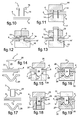
- the punching member (7) consists of a pin (10) with head (8) and piercing tip (9).
- the head (8) of the pin (10) bears against the outer plate (2) of one of the plates (4), while its tip (9) bears against the outer plate (2) the other plate (5), after matting to form a flap (9 ').
- this pin (10) is forcefully introduced through the plates (4, 5) so as to perforate them and emerge at its end provided with the tip (9).
- an anvil (11) is placed against the head (8) of the pin (10), while a hammer (12) deforms its tip (9) to fold it by crushing against the corresponding plate (2).
- the punching member (7) consists of a clip (13) having a pair of perforating tabs whose ends are folded to form flaps (13 ').
- the legs are likely to be in number greater than two, and can be indifferently folded inwards or outwards as illustrated.
- the punching member (7) consists of a pin (14) axially recessed.
- This pin (14) has a head (15) bearing against the outer sheet (2) of a first plate (4), its other end being crushed by a tool (16) to form a flap (14 ') against the outer plate (2) of the second plate (5).
- a guide (17) is placed against the second plate (5), to prevent deformation of the plates (4,5) during the punching step.
- the cut material is compressed inside the recess of the pin (14), which constitutes a chamber (18) for receiving this material, and prevents the latter from being a source pollution.
- the tool (16) is not only a flap member of the end of the pin (14), but also a compression member of the cut material inside the receiving chamber (18).
- the inner recess of the pin (14) is closed by the head (15).
- the tool (16) flap end of the pin (14) comprises a relief (19) for compressing the cut material of the plates (4,5) against the inner face of the head (15) of the pawn (14).
- the internal recess of the pin (14) opens out through the head (15).
- the outlet of the recess of the pin (14) allows the centering of the latter by means of a tool (20).
- This tool (20) comprises a centering drum intended to be housed inside the recess of the pin (14).
- the recess emerging from the pin (14) is used to form a passage (21) for the passage of a rod (22) equipping a tool (23) for ejecting the material carved plates (4,5).
- the ejection tool (23) is integral with the flap tool (16), or forms with the latter (16) a one-piece tool.
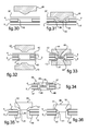
- the fixing means comprise cooperating members.
- One of these members is constituted by a pin (24) with a punching head (25), the other member being constituted by a flanged bowl (26) for receiving the perforating end (27) of the pawn (24).
- a striking tool (28) pushes the pin (24) through the plates (4,5).
- An anvil (29) is disposed against the corresponding plate (5) to prevent deformation of the plates (4,5).
- the anvil (29) has a recess (29 '), preferably circular, to allow the passage of a material reflux from the plates (4,5) during the establishment of the pin (24).
- the rim cup (26) is attached by being held by a first electrode (30).
- a second electrode (31) is placed against the head (25) of the pin (24) to weld the pin (24) and the bowl (26) together.
- This welding operation can be performed by capacitor discharge for example.
- the piercing end (27) and the bowl (26) have conical bearing bearing surfaces, through which they are welded to each other.
- the pin (24) is full.
- the pin (24) is axially hollowed out, the recess possibly constituting a passage (21) for the passage of a rod (22) of a tool.
- the plates (4, 5) are assembled together by means of a plate (32) superposed on a first plate (4).
- the plate (32) comprises tabs (33) formed by cutting and folding.
- the tabs (33) are likely to be aligned, or to be arranged in staggered rows for a more balanced maintenance of the plates (4,5) between them.
- Cutouts (34) are provided beforehand through the plates (4, 5) for passage through the tabs (33) to the outer sheet (2) of the second plate (5).
- a single plate (32) is placed against one of the plates (4), while according to the embodiments shown in Fig.24 to Figs. 29, the plates (4,5) are provided with a respective plate (32), the tongues (33) are folded from one to the other of the plates (4,5).
- the tabs (33) comprise a fold (35) of bearing against the outer face of the outer plate (2) of the second plate (5).
- this support is made through the plate (32) which is provided with the second plate (5).
- the plates (32) are placed in superposition against an outer sheet (2) of a respective plate (4,5).
- the tongues (33) of a plate (32) are deformed towards the tongues (33) of the other plate (32), by means of electrodes not shown in the figures.
- the tongues (33) are not only deformed to bear against each other via a return (33 '), but also are welded together under pressure.
- a cutout (36) is formed through a first plate (4), and a plate (37) is superimposed against this plate (4).
- An electrode (38) deforms the plate (37) to form a relief (39) which extends through the cutout (36) to the inner plate (3) of the second plate (5).
- the relief (39) is attached to the inner plate (3) of the second plate (5) via a solder joint (40).
- the relief (39) is formed by stamping prior to the establishment of the plate (37) against the first plate (4).
- a cutout (41) is formed through the two plates (4,5).
- a respective plate (42) is placed against the outer plate (2) of each of the plates (4,5).
- Two electrodes (43) deform a respective plate (42) to form reliefs shaped flanged bowl (44).
- These cups (44) extend through the cutout (41) until they are brought into contact in the middle zone of the latter.
- the reliefs (44) are welded to each other by their bottom by means of a weld joint (45).
- the plates may be replaced by a set of washers (46) shaped as a flanged bowl (44), or curved washers of the Belleville type, for example, whose flanges (47) respectively bear against each other.
- These washers (46) are fixed to each other by their bottom by means of a weld joint (48), by means of electrodes not shown.
- the washers (46) are planar and are deformed by tools and / or electrodes, similar to the electrodes (43) illustrated in FIG. 32, until their bottoms are brought into contact.
- a cutout (41) is previously formed through the plates (4,5). These are fixed to each other by means of cooperating members respectively assigned to each of the plates (4,5).
- One of these members is formed of a first stepped solid body (49), the other member being formed of a second shouldered body (50), which is axially recessed.
- the bodies (49,50) bear against the outer plate (2) of the plate (4,5) to which they are assigned via their shoulder (51), and extend partially through the cutout ( 41) until they come into contact with each other.
- the solid body (49) has a first conical bearing surface (52).
- the hollow body (50) and the solid body (49) are successively introduced inside the cutout (41), then the solid body (49) is pressed against the hollow body (50) via its surface.
- conical bearing (52) until crushing of the inner edge (53) of the corresponding end of the recessed body (50), forming thereon a second conical bearing surface cooperating with the first. This crushing is in particular carried out by means of electrodes assigned to each of the bodies (49,50), to fix them to each other by pressure welding, by capacitor discharge for example.
- the pressure associated with the flow of current causes a local melting of the material of the elements in contact with one another, which creates a solder joint.
- the pressure zones between the elements and the outer plates of the plates against which they respectively support, promote a robust assembly of the plates together.
- This method of assembly is quick to implement and causes a low thermal clearance, preserving the plates and in particular the inner layers of resin.
- no pollution is generated.
- the cutout (54) is formed through a first plate (4).
- This cutout (54) is on the illustrated embodiment of oblong shape, but could have any conformation.
- a solder joint (55), in particular made by adding material, is formed at the edge of the cutout (54) by being engaged on the inner sheets (3) superimposed plates (4,5).
- the weld joint (55) is obtained from the fusion of the inner sheets (3) of each of the plates (4,5), without adding material.
- the material supply is in particular carried out by soldering or brazing LASER, which makes it possible to obtain a fixing of the plates (4,5) between them without deterioration of the inner layer of resin (1), thanks to the precise focusing of the LASER beam on the areas to be welded, and in particular on the slices of the inner plates (3) of the plates (4,5).
- the LASER beam is a YAG beam, which is in particular conveyed by optical fiber.
- the welding head is preferably installed on an arm with automatic operation equipped with a system for detecting and monitoring the welding joint (55) practiced.
- the filler material is a metal, preferably copper-silicon-manganese type or copper-tin type for example, to allow a low temperature melting of the filler material.
- the cutouts (54) are likely to be formed through the first plate (4) in a regular or irregular manner, being aligned or arranged in staggered rows. According to an alternative embodiment, the cutouts (54) may be alternately formed in one and the other of the plates (4,5). Their position is also likely to be relatively arbitrary, without precise tolerances, by fixing the plates (4,5) together by welding an edge of the blank (54) formed in only one of the plates (4). In addition, no pollution is induced.
- the cutout (56) is formed in one of the plates (4,5), at the edge thereof.
- a solder joint (57) made by adding material is provided along the edge of the blank (56).
- This solder joint (57) is in particular a weld bead made by brazing or brazing, in particular by brazing LASER in the manner of the variant embodiment described in FIGS. 37 and 39.
- the cutout (56) is likely to have a rectilinear trajectory, without inflection. However, it is preferred to give this cutout (56) an irregular shape, such as sinusoidal in the illustrated embodiment.
- the respective edges of the plates (4,5) are offset relative to each other, the separation distance between these edges being capable of being indifferently constant or variable. Such a conformation of the cutout (56) allows a good peel strength of the plates (4,5) assembled.
- the cutout (56) formed in the plate (4) has a return (56 ') towards the outside of the plate (5).
- These arrangements are such that the contact surface between the solder joint (57) and the inner plate (3) of the plate (4) is optimized to improve the grip of the solder joint (57) on the plate (4) and finally to promote a stability of the welding.
- the two inner (3) and outer (2) plates of the plate (4) are curved, as illustrated in FIG. 41, or only the inner plate (3) of the plate (FIG. 4) has an inflection.
- the plates (4,5) are joined together orthogonally in their general plane.
- One of the plates (4) has first cutouts (58) formed in its edge, to form interlocking reliefs (59).
- the other plate (5) comprises second cutouts (60) of shape complementary to the conformation of the reliefs (59), for the purpose of interlocking the plates (4,5) between them.
- a solder joint (61) is provided, in particular by brazing or brazing LASER, at the edge of an emerging portion of the reliefs (59) out of the second cutouts (60) formed through the corresponding plate (5). This weld bead (61) is engaged on the outer plates (2) of the plates (4,5).
- each plate (4, 5) is capable of comprising one or more layers of material interposed between the metal sheets (2, 3), such as at least one other metal sheet, at least one other internal layer of resin, at least one other material.
Landscapes
- Engineering & Computer Science (AREA)
- Mechanical Engineering (AREA)
- General Engineering & Computer Science (AREA)
- Connection Of Plates (AREA)
Applications Claiming Priority (1)
| Application Number | Priority Date | Filing Date | Title |
|---|---|---|---|
| FR0509820A FR2891324B1 (fr) | 2005-09-26 | 2005-09-26 | Dispositif d'assemblage entre deux plaques stratifiees composees d'une couche de resine interposee entre deux toles metalliques |
Publications (2)
| Publication Number | Publication Date |
|---|---|
| EP1767792A2 true EP1767792A2 (de) | 2007-03-28 |
| EP1767792A3 EP1767792A3 (de) | 2007-10-31 |
Family
ID=36218241
Family Applications (1)
| Application Number | Title | Priority Date | Filing Date |
|---|---|---|---|
| EP06120303A Withdrawn EP1767792A3 (de) | 2005-09-26 | 2006-09-07 | Verbindungsvorrichtung zwischen zwei mehrschichtigen Platten aus einer Harzschicht zwischen zwei Metallblechen |
Country Status (5)
| Country | Link |
|---|---|
| US (1) | US7937816B2 (de) |
| EP (1) | EP1767792A3 (de) |
| JP (1) | JP2007092999A (de) |
| CN (1) | CN1955497A (de) |
| FR (1) | FR2891324B1 (de) |
Cited By (3)
| Publication number | Priority date | Publication date | Assignee | Title |
|---|---|---|---|---|
| FR2925941A1 (fr) * | 2008-01-02 | 2009-07-03 | Thierry Leclair | Systeme d'assemblage de feuille(s) et/ou de produit(s) plan(s) analogue(s) permettant une desunion |
| DE102008017981A1 (de) * | 2008-04-04 | 2009-10-08 | Volkswagen Ag | Niet und Verfahren zum Vernieten von Plattenerzeugnissen |
| WO2014173472A1 (de) * | 2013-04-22 | 2014-10-30 | Boellhoff Verbindungstechnik Gmbh | Setz-schweiss-gerät, modulare komponenten davon sowie ein mit ihm durchführbares kontinuierliches verbindungsverfahren |
Families Citing this family (18)
| Publication number | Priority date | Publication date | Assignee | Title |
|---|---|---|---|---|
| DE102009045791A1 (de) * | 2009-10-19 | 2011-05-12 | Zf Friedrichshafen Ag | Niet, Nietvorrichtung und Nietverfahren |
| DE102011006145A1 (de) * | 2011-03-25 | 2012-09-27 | Federal-Mogul Sealing Systems Gmbh | Verbundmaterial mit Prägung und Mikroperforierung |
| CN102760953B (zh) * | 2011-04-29 | 2015-09-16 | 深圳光启高等理工研究院 | 一种超材料组装结构及其组装方法 |
| US8966734B2 (en) * | 2011-09-23 | 2015-03-03 | GM Global Technology Operations LLC | Method of joining magnesium |
| DE102011122037A1 (de) * | 2011-12-22 | 2013-06-27 | Kathrein-Werke Kg | Verfahren zur Herstellung einer elektrischen Hochfrequenz-Verbindung zwischen zwei Plattenabschnitten sowie eine zugehörige elektrische Hochfrequenz-Verbindung |
| JP5893955B2 (ja) | 2012-02-27 | 2016-03-23 | 株式会社神戸製鋼所 | 発泡樹脂芯材複合板の締結構造の製造方法 |
| KR101483226B1 (ko) * | 2013-09-11 | 2015-01-16 | 주식회사 성우하이텍 | 접합패널 및 그 접합방법 |
| EP2860407B1 (de) * | 2013-10-08 | 2017-01-18 | MAGNA STEYR Fahrzeugtechnik AG & Co KG | Strukturbauteil |
| JP6252747B2 (ja) * | 2013-11-22 | 2017-12-27 | ポップリベット・ファスナー株式会社 | 接合装置及び接合方法 |
| KR101558208B1 (ko) | 2013-12-30 | 2015-10-08 | 주식회사 성우하이텍 | 패널의 스폿 용접 방법 |
| DE102014208513B4 (de) * | 2014-05-07 | 2021-01-21 | Bayerische Motoren Werke Aktiengesellschaft | Verfahren zur Befestigung mehrerer Werkstücke mittels eines hohlen Nietelements |
| CN107107268A (zh) * | 2014-12-23 | 2017-08-29 | 麦格纳国际公司 | 激光束局部化涂覆的方法 |
| KR20170069379A (ko) * | 2015-12-10 | 2017-06-21 | 현대자동차주식회사 | 복합재 연결유닛 및 조립패널 |
| US10576532B2 (en) * | 2015-12-14 | 2020-03-03 | GM Global Technology Operations LLC | Systems and methods for joining components by riveting |
| DE102016118109A1 (de) * | 2016-09-26 | 2018-03-29 | Newfrey Llc | Fügeverfahren zum vorlochfreien Verbinden von wenigstens einem ersten Bauteil mit einem zweiten Bauteil |
| KR20190051315A (ko) * | 2017-11-06 | 2019-05-15 | 울산대학교 산학협력단 | 통전압접방법 |
| CN109591895A (zh) * | 2018-11-08 | 2019-04-09 | 重庆腾海工贸有限公司 | 一种顶盖后横梁组件 |
| CN120055110B (zh) * | 2025-04-28 | 2025-07-15 | 江西和润宇电源科技有限公司 | 多层复合金属铅酸蓄电池板栅的连续铸造层压成型装置 |
Family Cites Families (22)
| Publication number | Priority date | Publication date | Assignee | Title |
|---|---|---|---|---|
| US2626687A (en) * | 1949-05-23 | 1953-01-27 | Ivan A Williams | Cleft fastener for uniting materials and method of forming the same |
| US2688890A (en) * | 1952-08-09 | 1954-09-14 | Ivan A Williams | Method of uniting superimposed metal sheets |
| US2814481A (en) * | 1952-08-16 | 1957-11-26 | Gen Motors Corp | Laminated spring |
| US2959495A (en) * | 1954-03-11 | 1960-11-08 | Patent & Licensing Corp | Vibration deadening felts |
| US3010199A (en) * | 1955-02-24 | 1961-11-28 | Smith | Tool and method for securing sheet metal pieces together |
| US2901816A (en) * | 1955-02-24 | 1959-09-01 | Smith | Tool and method for securing sheet metal pieces together |
| DE1125871B (de) * | 1956-07-31 | 1962-03-22 | Edoardo G Bianca | Verfahren zum Verbinden von Blechteilen, insbesondere bei der Herstellung von sich konisch verjuengenden Rohrstuecken fuer Rohrmaste |
| JPS5429270U (de) * | 1977-07-28 | 1979-02-26 | ||
| JPS56120805A (en) * | 1980-02-26 | 1981-09-22 | Tokyo Shibaura Electric Co | Joining device of plate like member |
| JPS60260713A (ja) * | 1984-06-07 | 1985-12-23 | 日本鋼管株式会社 | ボルト等の締結手段によるラミネ−ト鋼板の締結方法 |
| US5074726A (en) * | 1988-11-28 | 1991-12-24 | The B. F. Goodrich Company | Blind fastener |
| US4828438A (en) * | 1988-03-17 | 1989-05-09 | The B.F. Goodrich Company | Blind fastener |
| JPH08128425A (ja) * | 1994-11-02 | 1996-05-21 | Mitsubishi Chem Corp | リベットの施工方法および当該施工方法で得られた建築資材 |
| JP3287715B2 (ja) * | 1994-11-30 | 2002-06-04 | 三菱化学株式会社 | リベットの施工方法 |
| DE19540904A1 (de) * | 1994-11-02 | 1996-05-09 | Mitsubishi Chem Corp | Nietverfahren und hierdurch hergestellte Bauplatte |
| IT1267357B1 (it) * | 1994-12-23 | 1997-01-28 | Fiat Auto Spa | Metodo di unione per saldatura tra elementi diversi. |
| US6235409B1 (en) * | 1997-12-17 | 2001-05-22 | Alcoa Inc. | Aluminum laminate |
| JP2000081011A (ja) * | 1998-09-04 | 2000-03-21 | Fukui Byora Co Ltd | プラスチック段ボール板と補強板のかしめ締結方法及びその方法に用いられるかしめ用ポンチ並びにその方法によって得られるプラスチック段ボール箱 |
| JP2001099113A (ja) * | 1999-09-27 | 2001-04-10 | Nippon Steel Corp | めっき鋼板、塗装鋼板の機械的接合方法および接合用材料 |
| US6365276B1 (en) * | 1999-11-12 | 2002-04-02 | Mitsushita Chemical America, Inc. | Coated metal articles methods for preparing the same laminated composites containing the same, and methods for preparing such laminated composites |
| JP2002070892A (ja) * | 2000-08-31 | 2002-03-08 | Mitsubishi Heavy Ind Ltd | 電磁クラッチおよび該電磁クラッチを備えた圧縮機 |
| WO2006102592A1 (en) * | 2005-03-24 | 2006-09-28 | 3M Innovative Properties Company | Metallized films and articles containing the same |
-
2005
- 2005-09-26 FR FR0509820A patent/FR2891324B1/fr not_active Expired - Fee Related
-
2006
- 2006-09-07 EP EP06120303A patent/EP1767792A3/de not_active Withdrawn
- 2006-09-12 US US11/519,263 patent/US7937816B2/en not_active Expired - Fee Related
- 2006-09-26 CN CNA2006101395687A patent/CN1955497A/zh active Pending
- 2006-09-26 JP JP2006259837A patent/JP2007092999A/ja active Pending
Cited By (5)
| Publication number | Priority date | Publication date | Assignee | Title |
|---|---|---|---|---|
| FR2925941A1 (fr) * | 2008-01-02 | 2009-07-03 | Thierry Leclair | Systeme d'assemblage de feuille(s) et/ou de produit(s) plan(s) analogue(s) permettant une desunion |
| DE102008017981A1 (de) * | 2008-04-04 | 2009-10-08 | Volkswagen Ag | Niet und Verfahren zum Vernieten von Plattenerzeugnissen |
| WO2014173472A1 (de) * | 2013-04-22 | 2014-10-30 | Boellhoff Verbindungstechnik Gmbh | Setz-schweiss-gerät, modulare komponenten davon sowie ein mit ihm durchführbares kontinuierliches verbindungsverfahren |
| US10207458B2 (en) | 2013-04-22 | 2019-02-19 | Böllhoff Verbindungstechnik GmbH | Setting welding device, modular components thereof and a continuous connecting method that can be carried out with such a device |
| US11084229B2 (en) | 2013-04-22 | 2021-08-10 | Böllhoff Verbindungstechnik GmbH | Setting welding device, modular components thereof and a continuous connecting method that can be carried out with such a device |
Also Published As
| Publication number | Publication date |
|---|---|
| CN1955497A (zh) | 2007-05-02 |
| FR2891324A1 (fr) | 2007-03-30 |
| JP2007092999A (ja) | 2007-04-12 |
| US7937816B2 (en) | 2011-05-10 |
| EP1767792A3 (de) | 2007-10-31 |
| FR2891324B1 (fr) | 2011-02-18 |
| US20070068116A1 (en) | 2007-03-29 |
Similar Documents
| Publication | Publication Date | Title |
|---|---|---|
| EP1767792A2 (de) | Verbindungsvorrichtung zwischen zwei mehrschichtigen Platten aus einer Harzschicht zwischen zwei Metallblechen | |
| EP2416946B1 (de) | Verfahren zur herstellung einer aus einem thermoplastischen matrixverbundmaterial hergestellten versteiften platte und sich ergebende platte | |
| JP6101513B2 (ja) | 金属箔の重ね接合方法及び接合構造体 | |
| EP2656150B1 (de) | Montageverfahren einer komponente ohne kunststoffbereich | |
| EP3960356A1 (de) | Einsatz zum verbinden eines ersten teils mit einem zweiten durch elektrisches widerstandsschweissen | |
| FR2802453A1 (fr) | Procede d'assemblage sans soudure de toles, de type boutonnage | |
| EP3185086B1 (de) | Applique für zifferblatt einer uhr | |
| EP0340094B1 (de) | Verfahren zum Verbinden von einem ersten Gegenstand aus Kunststoff und einem zweiten Gegenstand durch Nieten. | |
| EP2829385A1 (de) | Kombiniertes Verfahren zum Lochstanzen und Nieten | |
| FR3058661B1 (fr) | Procede de soudage par impulsion magnetique d’un empilement de feuillets | |
| FR2946712A1 (fr) | Bielle pour la construction aeronautique et procede de fabrication d'une telle bielle | |
| EP3448694B1 (de) | Kraftfahrzeugrad mit einer felge aus aluminium und einer scheibe aus stahl, die durch geschweisste stifte zusammengefügt sind | |
| CN110582650B (zh) | 接合体、汽车用座椅框架以及接合方法 | |
| EP3145795B1 (de) | An die seiten der karosserie hartgelötetes kraftfahrzeugdach | |
| EP4415924B1 (de) | Verfahren zum verbinden zweier blechteile durch verkleben und verschweissen | |
| EP4174330B1 (de) | Verfahren und befestigung zum zusammenbau mindestens zweier elementarer bauteile | |
| EP1543893B1 (de) | Verfahren zum Kröpfen eines Profils und damit hergestelltes Profil | |
| WO2018193839A1 (ja) | 接合体、自動車用シートフレームおよび接合方法 | |
| EP3801970B1 (de) | Verfahren zur montage eines ersten teils und eines zweiten teils mittels eines einsatzes | |
| FR3147727A1 (fr) | Pion a souder | |
| WO2009133305A1 (fr) | Procede et dispositif de fixation d'un equipement sur un revetement compressible recouvrant une structure de support | |
| WO2001029498A1 (fr) | Dispositif et procede de fixation d'un systeme d'amorçage sur un corps d'une grenade | |
| EP4663340A1 (de) | Futter | |
| WO2025153782A1 (fr) | Element de jonction assurant un assemblage multi-materiaux de trois epaisseurs | |
| FR2997879A1 (fr) | Procede de soudage a grande vitesse de deux parois de deux pieces |
Legal Events
| Date | Code | Title | Description |
|---|---|---|---|
| PUAI | Public reference made under article 153(3) epc to a published international application that has entered the european phase |
Free format text: ORIGINAL CODE: 0009012 |
|
| AK | Designated contracting states |
Kind code of ref document: A2 Designated state(s): AT BE BG CH CY CZ DE DK EE ES FI FR GB GR HU IE IS IT LI LT LU LV MC NL PL PT RO SE SI SK TR |
|
| AX | Request for extension of the european patent |
Extension state: AL BA HR MK YU |
|
| PUAL | Search report despatched |
Free format text: ORIGINAL CODE: 0009013 |
|
| AK | Designated contracting states |
Kind code of ref document: A3 Designated state(s): AT BE BG CH CY CZ DE DK EE ES FI FR GB GR HU IE IS IT LI LT LU LV MC NL PL PT RO SE SI SK TR |
|
| AX | Request for extension of the european patent |
Extension state: AL BA HR MK YU |
|
| AKX | Designation fees paid | ||
| REG | Reference to a national code |
Ref country code: DE Ref legal event code: 8566 |
|
| STAA | Information on the status of an ep patent application or granted ep patent |
Free format text: STATUS: THE APPLICATION IS DEEMED TO BE WITHDRAWN |
|
| 18D | Application deemed to be withdrawn |
Effective date: 20080503 |