EP1767916A2 - Druckwandlerpackung für einen Sammler - Google Patents
Druckwandlerpackung für einen Sammler Download PDFInfo
- Publication number
- EP1767916A2 EP1767916A2 EP06019995A EP06019995A EP1767916A2 EP 1767916 A2 EP1767916 A2 EP 1767916A2 EP 06019995 A EP06019995 A EP 06019995A EP 06019995 A EP06019995 A EP 06019995A EP 1767916 A2 EP1767916 A2 EP 1767916A2
- Authority
- EP
- European Patent Office
- Prior art keywords
- package
- transducers
- pressure
- transducer
- housing
- Prior art date
- Legal status (The legal status is an assumption and is not a legal conclusion. Google has not performed a legal analysis and makes no representation as to the accuracy of the status listed.)
- Withdrawn
Links
- 239000000758 substrate Substances 0.000 claims abstract description 30
- 239000012530 fluid Substances 0.000 claims abstract description 27
- 230000005540 biological transmission Effects 0.000 claims description 28
- 238000004891 communication Methods 0.000 claims description 12
- 238000000034 method Methods 0.000 claims description 7
- 238000004519 manufacturing process Methods 0.000 claims description 3
- 239000002184 metal Substances 0.000 claims description 3
- 239000011810 insulating material Substances 0.000 claims description 2
- 230000008878 coupling Effects 0.000 claims 5
- 238000010168 coupling process Methods 0.000 claims 5
- 238000005859 coupling reaction Methods 0.000 claims 5
- 238000012544 monitoring process Methods 0.000 abstract description 5
- 238000007789 sealing Methods 0.000 description 6
- 238000013461 design Methods 0.000 description 3
- 238000011109 contamination Methods 0.000 description 2
- 238000012937 correction Methods 0.000 description 2
- 238000010586 diagram Methods 0.000 description 2
- 239000000463 material Substances 0.000 description 2
- 230000035945 sensitivity Effects 0.000 description 2
- 230000003321 amplification Effects 0.000 description 1
- 230000000712 assembly Effects 0.000 description 1
- 238000000429 assembly Methods 0.000 description 1
- 230000001276 controlling effect Effects 0.000 description 1
- 230000000694 effects Effects 0.000 description 1
- 239000000945 filler Substances 0.000 description 1
- 239000011521 glass Substances 0.000 description 1
- 238000012986 modification Methods 0.000 description 1
- 230000004048 modification Effects 0.000 description 1
- 238000003199 nucleic acid amplification method Methods 0.000 description 1
- 230000000750 progressive effect Effects 0.000 description 1
- 230000001105 regulatory effect Effects 0.000 description 1
Images


Classifications
-
- G—PHYSICS
- G01—MEASURING; TESTING
- G01L—MEASURING FORCE, STRESS, TORQUE, WORK, MECHANICAL POWER, MECHANICAL EFFICIENCY, OR FLUID PRESSURE
- G01L15/00—Devices or apparatus for measuring two or more fluid pressure values simultaneously
-
- G—PHYSICS
- G01—MEASURING; TESTING
- G01L—MEASURING FORCE, STRESS, TORQUE, WORK, MECHANICAL POWER, MECHANICAL EFFICIENCY, OR FLUID PRESSURE
- G01L19/00—Details of, or accessories for, apparatus for measuring steady or quasi-steady pressure of a fluent medium insofar as such details or accessories are not special to particular types of pressure gauges
- G01L19/14—Housings
- G01L19/142—Multiple part housings
-
- G—PHYSICS
- G01—MEASURING; TESTING
- G01L—MEASURING FORCE, STRESS, TORQUE, WORK, MECHANICAL POWER, MECHANICAL EFFICIENCY, OR FLUID PRESSURE
- G01L23/00—Devices or apparatus for measuring or indicating or recording rapid changes, such as oscillations, in the pressure of steam, gas, or liquid; Indicators for determining work or energy of steam, internal-combustion, or other fluid-pressure engines from the condition of the working fluid
- G01L23/24—Devices or apparatus for measuring or indicating or recording rapid changes, such as oscillations, in the pressure of steam, gas, or liquid; Indicators for determining work or energy of steam, internal-combustion, or other fluid-pressure engines from the condition of the working fluid specially adapted for measuring pressure in inlet or exhaust ducts of internal-combustion engines
-
- F—MECHANICAL ENGINEERING; LIGHTING; HEATING; WEAPONS; BLASTING
- F16—ENGINEERING ELEMENTS AND UNITS; GENERAL MEASURES FOR PRODUCING AND MAINTAINING EFFECTIVE FUNCTIONING OF MACHINES OR INSTALLATIONS; THERMAL INSULATION IN GENERAL
- F16H—GEARING
- F16H59/00—Control inputs to control units of change-speed- or reversing-gearings for conveying rotary motion
- F16H59/68—Inputs being a function of gearing status
- F16H2059/683—Sensing pressure in control systems or in fluid-controlled devices, e.g. by pressure sensors
-
- F—MECHANICAL ENGINEERING; LIGHTING; HEATING; WEAPONS; BLASTING
- F16—ENGINEERING ELEMENTS AND UNITS; GENERAL MEASURES FOR PRODUCING AND MAINTAINING EFFECTIVE FUNCTIONING OF MACHINES OR INSTALLATIONS; THERMAL INSULATION IN GENERAL
- F16H—GEARING
- F16H59/00—Control inputs to control units of change-speed- or reversing-gearings for conveying rotary motion
- F16H59/68—Inputs being a function of gearing status
Definitions
- the present invention relates to pressure sensing systems, and more particularly to a pressure sensing system that senses fluid pressure in a manifold having multiple ports.
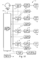
- the pressure supplied to each clutch ( Figure 1A) or to each control valve ( Figure 1 B) along the clutch's respective conduit 20 is sensed by a pressure transducer 24, which provides an electrical indication of the sensed pressure, as shown by a dashed line in Figures 1A and 1B, to an electronic transmission control unit (TCU) 26.
- the TCU 26 also receives an input in the form of a command pressure signal from a powertrain computer 28 that is programmed to provide the desired shift characteristics for the particular vehicle and engine-transmission combination.
- the pressure transducers 24 may comprise any appropriate pressure sensor, such as a piezoelectric sensor.
- the alignment between the pressure ports 52 and the transducers 24 allows the package 30 to be retrofitted into any pre-existing transmission system, if desired. This allows the package 30 to be easily manufactured separately from the TCU 26 and be attached to the TCU 26 without having to reconfigure the manifold 50 to accommodate the package 30.
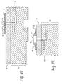
- FIG. 2A shows one embodiment where the support 62 in the package 30 is embedded in the housing 31 of the inventive package 30.
- a sealing structure may be included around the pressure port 52.
- an O-ring 80 acts as the sealing structure and is wedged between the manifold 50 and the support 58 to fluidically seal the pressure port 52.
- other sealing structures such as gasket material, may be used without departing from the scope of the invention.
- FIGS. 2D and 2E do not show a sealing structure, those of ordinary skill in the art will understand that any of the sealing structures shown in Figures 2A through 2C may be incorporated into the embodiments of Figures 2D and 2E without departing from the scope of the invention.
- the invention shortens the signal path between the manifold 50 and the transducers 24 and between the transducers 24 and the processor 70 reducing the complexity of the overall transmission control system and making it less sensitive to noise.
- Figures 3A and 3B illustrate a package configuration where the transducers 24 are arranged roughly in a circular or hexagonal shape on their respective substrates 61.
- the transducers 24 and the processor 70 are housed in the package housing 31.
- Optional dams 73 or filler material may be included in the package 30 to stabilize the transducers 24 and processor 70 to prevent them from becoming jarred loose over time.
- the package housing 30 may also include a bolt hole 74 to allow the package 30 to be attached easily to the manifold 50 with a single bolt.
Landscapes
- Physics & Mathematics (AREA)
- General Physics & Mathematics (AREA)
- Chemical & Material Sciences (AREA)
- Engineering & Computer Science (AREA)
- Combustion & Propulsion (AREA)
- Measuring Fluid Pressure (AREA)
Applications Claiming Priority (1)
| Application Number | Priority Date | Filing Date | Title |
|---|---|---|---|
| US11/235,614 US7383735B2 (en) | 2005-09-26 | 2005-09-26 | Pressure transducer package for a manifold |
Publications (2)
| Publication Number | Publication Date |
|---|---|
| EP1767916A2 true EP1767916A2 (de) | 2007-03-28 |
| EP1767916A3 EP1767916A3 (de) | 2014-04-09 |
Family
ID=37547529
Family Applications (1)
| Application Number | Title | Priority Date | Filing Date |
|---|---|---|---|
| EP06019995.7A Withdrawn EP1767916A3 (de) | 2005-09-26 | 2006-09-25 | Druckwandlerpackung für einen Sammler |
Country Status (3)
| Country | Link |
|---|---|
| US (1) | US7383735B2 (de) |
| EP (1) | EP1767916A3 (de) |
| JP (1) | JP2007093604A (de) |
Cited By (1)
| Publication number | Priority date | Publication date | Assignee | Title |
|---|---|---|---|---|
| EP3719470A2 (de) * | 2019-04-05 | 2020-10-07 | Honeywell International Inc. | Drucksensor mit mehreren druckerfassungselementen |
Families Citing this family (2)
| Publication number | Priority date | Publication date | Assignee | Title |
|---|---|---|---|---|
| EP2647885B1 (de) * | 2011-03-31 | 2016-04-27 | Aisin AW Co., Ltd. | Getriebesteuerungsvorrichtung und verfahren zur bestimmung des in einem getriebe erzeugten bremsmoments |
| JP6701931B2 (ja) * | 2016-05-02 | 2020-05-27 | 日本電産トーソク株式会社 | 油圧センサの取付け構造 |
Citations (2)
| Publication number | Priority date | Publication date | Assignee | Title |
|---|---|---|---|---|
| US5803123A (en) * | 1994-06-03 | 1998-09-08 | Keystone International Holdings Corp. | Mounting system for pressure transmitters |
| WO2000030909A1 (en) * | 1998-11-25 | 2000-06-02 | Kelsey-Hayes Company | Structure for mounting a cluster of pressure sensors upon an electro-hydraulic brake system control unit |
Family Cites Families (14)
| Publication number | Priority date | Publication date | Assignee | Title |
|---|---|---|---|---|
| JPH10197381A (ja) * | 1997-01-10 | 1998-07-31 | Nippon Aleph Corp | センサ装置 |
| US6220101B1 (en) * | 1998-02-03 | 2001-04-24 | Ssi Technologies, Inc. | Apparatus for measuring multiple pressures |
| EP1068120B1 (de) * | 1998-03-31 | 2002-07-03 | Continental Teves AG & Co. oHG | Drucksensorbaugruppe |
| DE19834212A1 (de) * | 1998-07-29 | 2000-02-10 | Siemens Ag | Steuergerät in einem Kraftfahrzeug und von diesem verwendeter Drucksensor |
| EP1108163B1 (de) * | 1998-08-24 | 2002-03-06 | Siemens Aktiengesellschaft | Steuergerät in einem kraftfahrzeug |
| JP3432780B2 (ja) * | 2000-02-22 | 2003-08-04 | 株式会社日立製作所 | 半導体圧力センサ |
| US6883874B2 (en) * | 2000-09-14 | 2005-04-26 | New York Air Brake Corporation | Pressure sensor module |
| US20020038975A1 (en) * | 2000-09-15 | 2002-04-04 | Mccurdy William B. | Pressure sensor module |
| US6687642B2 (en) * | 2001-01-26 | 2004-02-03 | Texas Instruments Incorporated | Condition responsive sense system and method |
| JP2003254849A (ja) * | 2002-02-28 | 2003-09-10 | Sunx Ltd | 圧力検出器及び圧力センサ |
| US20040118466A1 (en) * | 2002-12-19 | 2004-06-24 | Eaton Corporation | Electro-hydraulic manifold assembly and pressure sensor therefor |
| US6807472B2 (en) * | 2002-12-23 | 2004-10-19 | Eaton Corporation | Closed loop control of shifting clutch actuators in an automatic speed change transmission |
| US6929031B2 (en) * | 2003-03-28 | 2005-08-16 | Eaton Corporation | Electro-hydraulic manifold assembly with lead frame mounted pressure sensors |
| US20050070205A1 (en) * | 2003-09-30 | 2005-03-31 | Speedfam-Ipec Corporation | Integrated pressure control system for workpiece carrier |
-
2005
- 2005-09-26 US US11/235,614 patent/US7383735B2/en not_active Expired - Fee Related
-
2006
- 2006-09-25 EP EP06019995.7A patent/EP1767916A3/de not_active Withdrawn
- 2006-09-26 JP JP2006260570A patent/JP2007093604A/ja active Pending
Patent Citations (2)
| Publication number | Priority date | Publication date | Assignee | Title |
|---|---|---|---|---|
| US5803123A (en) * | 1994-06-03 | 1998-09-08 | Keystone International Holdings Corp. | Mounting system for pressure transmitters |
| WO2000030909A1 (en) * | 1998-11-25 | 2000-06-02 | Kelsey-Hayes Company | Structure for mounting a cluster of pressure sensors upon an electro-hydraulic brake system control unit |
Cited By (2)
| Publication number | Priority date | Publication date | Assignee | Title |
|---|---|---|---|---|
| EP3719470A2 (de) * | 2019-04-05 | 2020-10-07 | Honeywell International Inc. | Drucksensor mit mehreren druckerfassungselementen |
| US11650119B2 (en) | 2019-04-05 | 2023-05-16 | Honeywell International Inc. | Pressure sensor with multiple pressure sensing elements |
Also Published As
| Publication number | Publication date |
|---|---|
| JP2007093604A (ja) | 2007-04-12 |
| US20070068268A1 (en) | 2007-03-29 |
| US7383735B2 (en) | 2008-06-10 |
| EP1767916A3 (de) | 2014-04-09 |
Similar Documents
| Publication | Publication Date | Title |
|---|---|---|
| EP1462681B1 (de) | Elektro-hydraulische Sammelplatte mit auf einem Leiterrahmen montierten Drucksensoren | |
| US7908734B2 (en) | Manifold assembly having a centralized pressure sensing package | |
| US20090299583A1 (en) | Method and apparatus for detecting and compensating for pressure transducer errors | |
| EP1508731B1 (de) | Elektromagnetventil und Herstellungsverfahren | |
| JP2008528897A (ja) | 圧力センサを内蔵する電磁圧力制御弁装置 | |
| US7486996B2 (en) | Transmission control unit having pressure transducer package | |
| EP1437532A2 (de) | Elektro-Hydraulische Ventilblckanordnung und Drucksensor hierfür | |
| US7909721B2 (en) | Fluid pressure control assembly | |
| US7383735B2 (en) | Pressure transducer package for a manifold | |
| US6544138B2 (en) | Electro-hydraulic module for automatic transmission control | |
| US20060032541A1 (en) | Electro-hydraulic manifold assembly with mounted pressure sensors | |
| WO2003016753A1 (en) | Electro-hydraulic module for transmission control | |
| JPH05196061A (ja) | アクチュエータ制御装置 | |
| WO2002066868A1 (en) | Mechatronics pressure sensor and contact |
Legal Events
| Date | Code | Title | Description |
|---|---|---|---|
| PUAI | Public reference made under article 153(3) epc to a published international application that has entered the european phase |
Free format text: ORIGINAL CODE: 0009012 |
|
| AK | Designated contracting states |
Kind code of ref document: A2 Designated state(s): AT BE BG CH CY CZ DE DK EE ES FI FR GB GR HU IE IS IT LI LT LU LV MC NL PL PT RO SE SI SK TR |
|
| AX | Request for extension of the european patent |
Extension state: AL BA HR MK YU |
|
| PUAL | Search report despatched |
Free format text: ORIGINAL CODE: 0009013 |
|
| AK | Designated contracting states |
Kind code of ref document: A3 Designated state(s): AT BE BG CH CY CZ DE DK EE ES FI FR GB GR HU IE IS IT LI LT LU LV MC NL PL PT RO SE SI SK TR |
|
| AX | Request for extension of the european patent |
Extension state: AL BA HR MK RS |
|
| RIC1 | Information provided on ipc code assigned before grant |
Ipc: G01L 19/00 20060101ALI20140228BHEP Ipc: F16H 59/68 20060101ALI20140228BHEP Ipc: G01L 9/00 20060101ALI20140228BHEP Ipc: G01L 15/00 20060101AFI20140228BHEP Ipc: G01L 19/14 20060101ALI20140228BHEP Ipc: G01L 23/24 20060101ALI20140228BHEP |
|
| 17P | Request for examination filed |
Effective date: 20140523 |
|
| RBV | Designated contracting states (corrected) |
Designated state(s): DE FR GB IT PL SE |
|
| AKX | Designation fees paid |
Designated state(s): DE FR GB IT PL SE |
|
| AXX | Extension fees paid |
Extension state: HR Extension state: RS Extension state: BA Extension state: AL Extension state: MK |
|
| 17Q | First examination report despatched |
Effective date: 20160603 |
|
| GRAP | Despatch of communication of intention to grant a patent |
Free format text: ORIGINAL CODE: EPIDOSNIGR1 |
|
| STAA | Information on the status of an ep patent application or granted ep patent |
Free format text: STATUS: GRANT OF PATENT IS INTENDED |
|
| INTG | Intention to grant announced |
Effective date: 20170222 |
|
| STAA | Information on the status of an ep patent application or granted ep patent |
Free format text: STATUS: THE APPLICATION IS DEEMED TO BE WITHDRAWN |
|
| 18D | Application deemed to be withdrawn |
Effective date: 20170705 |