EP1768166A2 - Verfahren zur Kunstharzverkapselung elektronischer Bauelemente und zugehörige Vorrichtung - Google Patents
Verfahren zur Kunstharzverkapselung elektronischer Bauelemente und zugehörige Vorrichtung Download PDFInfo
- Publication number
- EP1768166A2 EP1768166A2 EP06254901A EP06254901A EP1768166A2 EP 1768166 A2 EP1768166 A2 EP 1768166A2 EP 06254901 A EP06254901 A EP 06254901A EP 06254901 A EP06254901 A EP 06254901A EP 1768166 A2 EP1768166 A2 EP 1768166A2
- Authority
- EP
- European Patent Office
- Prior art keywords
- mold
- resin
- seal
- molding
- substrate
- Prior art date
- Legal status (The legal status is an assumption and is not a legal conclusion. Google has not performed a legal analysis and makes no representation as to the accuracy of the status listed.)
- Pending
Links
Images

Classifications
-
- H—ELECTRICITY
- H10—SEMICONDUCTOR DEVICES; ELECTRIC SOLID-STATE DEVICES NOT OTHERWISE PROVIDED FOR
- H10W—GENERIC PACKAGES, INTERCONNECTIONS, CONNECTORS OR OTHER CONSTRUCTIONAL DETAILS OF DEVICES COVERED BY CLASS H10
- H10W74/00—Encapsulations, e.g. protective coatings
- H10W74/01—Manufacture or treatment
- H10W74/016—Manufacture or treatment using moulds
-
- B—PERFORMING OPERATIONS; TRANSPORTING
- B29—WORKING OF PLASTICS; WORKING OF SUBSTANCES IN A PLASTIC STATE IN GENERAL
- B29C—SHAPING OR JOINING OF PLASTICS; SHAPING OF MATERIAL IN A PLASTIC STATE, NOT OTHERWISE PROVIDED FOR; AFTER-TREATMENT OF THE SHAPED PRODUCTS, e.g. REPAIRING
- B29C45/00—Injection moulding, i.e. forcing the required volume of moulding material through a nozzle into a closed mould; Apparatus therefor
- B29C45/02—Transfer moulding, i.e. transferring the required volume of moulding material by a plunger from a "shot" cavity into a mould cavity
-
- B—PERFORMING OPERATIONS; TRANSPORTING
- B29—WORKING OF PLASTICS; WORKING OF SUBSTANCES IN A PLASTIC STATE IN GENERAL
- B29C—SHAPING OR JOINING OF PLASTICS; SHAPING OF MATERIAL IN A PLASTIC STATE, NOT OTHERWISE PROVIDED FOR; AFTER-TREATMENT OF THE SHAPED PRODUCTS, e.g. REPAIRING
- B29C45/00—Injection moulding, i.e. forcing the required volume of moulding material through a nozzle into a closed mould; Apparatus therefor
- B29C45/17—Component parts, details or accessories; Auxiliary operations
- B29C45/26—Moulds
- B29C45/32—Moulds having several axially spaced mould cavities, i.e. for making several separated articles
-
- B—PERFORMING OPERATIONS; TRANSPORTING
- B29—WORKING OF PLASTICS; WORKING OF SUBSTANCES IN A PLASTIC STATE IN GENERAL
- B29C—SHAPING OR JOINING OF PLASTICS; SHAPING OF MATERIAL IN A PLASTIC STATE, NOT OTHERWISE PROVIDED FOR; AFTER-TREATMENT OF THE SHAPED PRODUCTS, e.g. REPAIRING
- B29C45/00—Injection moulding, i.e. forcing the required volume of moulding material through a nozzle into a closed mould; Apparatus therefor
- B29C45/17—Component parts, details or accessories; Auxiliary operations
- B29C45/64—Mould opening, closing or clamping devices
-
- B—PERFORMING OPERATIONS; TRANSPORTING
- B29—WORKING OF PLASTICS; WORKING OF SUBSTANCES IN A PLASTIC STATE IN GENERAL
- B29C—SHAPING OR JOINING OF PLASTICS; SHAPING OF MATERIAL IN A PLASTIC STATE, NOT OTHERWISE PROVIDED FOR; AFTER-TREATMENT OF THE SHAPED PRODUCTS, e.g. REPAIRING
- B29C45/00—Injection moulding, i.e. forcing the required volume of moulding material through a nozzle into a closed mould; Apparatus therefor
- B29C45/14—Injection moulding, i.e. forcing the required volume of moulding material through a nozzle into a closed mould; Apparatus therefor incorporating preformed parts or layers, e.g. injection moulding around inserts or for coating articles
- B29C45/14065—Positioning or centering articles in the mould
- B29C2045/14147—Positioning or centering articles in the mould using pins or needles penetrating through the insert
-
- B—PERFORMING OPERATIONS; TRANSPORTING
- B29—WORKING OF PLASTICS; WORKING OF SUBSTANCES IN A PLASTIC STATE IN GENERAL
- B29C—SHAPING OR JOINING OF PLASTICS; SHAPING OF MATERIAL IN A PLASTIC STATE, NOT OTHERWISE PROVIDED FOR; AFTER-TREATMENT OF THE SHAPED PRODUCTS, e.g. REPAIRING
- B29C45/00—Injection moulding, i.e. forcing the required volume of moulding material through a nozzle into a closed mould; Apparatus therefor
- B29C45/17—Component parts, details or accessories; Auxiliary operations
- B29C45/64—Mould opening, closing or clamping devices
- B29C2045/648—Rack and pinion means for mould opening and closing a pair of mould halves
-
- B—PERFORMING OPERATIONS; TRANSPORTING
- B29—WORKING OF PLASTICS; WORKING OF SUBSTANCES IN A PLASTIC STATE IN GENERAL
- B29C—SHAPING OR JOINING OF PLASTICS; SHAPING OF MATERIAL IN A PLASTIC STATE, NOT OTHERWISE PROVIDED FOR; AFTER-TREATMENT OF THE SHAPED PRODUCTS, e.g. REPAIRING
- B29C45/00—Injection moulding, i.e. forcing the required volume of moulding material through a nozzle into a closed mould; Apparatus therefor
- B29C45/14—Injection moulding, i.e. forcing the required volume of moulding material through a nozzle into a closed mould; Apparatus therefor incorporating preformed parts or layers, e.g. injection moulding around inserts or for coating articles
- B29C45/14065—Positioning or centering articles in the mould
-
- B—PERFORMING OPERATIONS; TRANSPORTING
- B29—WORKING OF PLASTICS; WORKING OF SUBSTANCES IN A PLASTIC STATE IN GENERAL
- B29C—SHAPING OR JOINING OF PLASTICS; SHAPING OF MATERIAL IN A PLASTIC STATE, NOT OTHERWISE PROVIDED FOR; AFTER-TREATMENT OF THE SHAPED PRODUCTS, e.g. REPAIRING
- B29C45/00—Injection moulding, i.e. forcing the required volume of moulding material through a nozzle into a closed mould; Apparatus therefor
- B29C45/14—Injection moulding, i.e. forcing the required volume of moulding material through a nozzle into a closed mould; Apparatus therefor incorporating preformed parts or layers, e.g. injection moulding around inserts or for coating articles
- B29C45/14639—Injection moulding, i.e. forcing the required volume of moulding material through a nozzle into a closed mould; Apparatus therefor incorporating preformed parts or layers, e.g. injection moulding around inserts or for coating articles for obtaining an insulating effect, e.g. for electrical components
- B29C45/14655—Injection moulding, i.e. forcing the required volume of moulding material through a nozzle into a closed mould; Apparatus therefor incorporating preformed parts or layers, e.g. injection moulding around inserts or for coating articles for obtaining an insulating effect, e.g. for electrical components connected to or mounted on a carrier, e.g. lead frame
Definitions
- the present invention relates to a method of seal-molding an electronic component of a relatively small size such as a semiconductor chip by a resin material, and to an apparatus for resin-seal-molding an electronic component used for implementing the method.
- a semiconductor package wherein an electronic component of a relatively small size such as a semiconductor chip is seal-molded by a resin material (hereinafter simply referred to as a semiconductor package).
- a so-called MAP type large substrate has strongly been required to have higher integration, higher reliability, and further compactness; that is, to be lighter, thinner, shorter, and smaller.
- molded product releasing means for releasing the molded product by forcibly ejecting the molded product with an ejector pin or the like is employed, coupled with the compactness of the molded product, there is a problem that the molded product body (resin-seal-molded body) may be damaged and a crack may occur, or it may be broken and its quality may be degraded.
- thermosetting resin material such as epoxy resin
- a large substrate is used.
- a conventional mold surface is provided with a recess (a clearance of a prescribed depth provided to a parting line (PL) face of a mold, as corresponding to the thickness of a substrate) for insert-setting a substrate.
- This recess invites the following problems.
- each site of a large substrate is not uniform, i.e., the thickness varies among each site. Additionally, it is common to simultaneously insert-set a large number of such large substrates to a mold surface. Therefore, clamping state is not uniform among the large substrates even if the large substrates are simultaneously applied with mold-clamping pressure. This sometimes causes part of the resin material to flow into between each of the large substrates and the mold surfaces, resulting in formation of resin flash on the substrate surface and on the mold surface. Conversely, if each of the substrates is applied with the clamping pressure so as to prevent the resin flash formation, there is an adverse effect that semiconductor elements or interconnections on the substrates are damaged if the clamping pressure is excessive.
- a pot (a portion for plasticizing a resin material) is provided inside the mold.
- a resin-molding cavity and a resin path for transferring the molten resin material constituted of a cull, a runner and the like for implementing communication between the cavity and the pot are formed as recesses.
- the portion for insert-setting the substrate, the pot portion, the resin path portion and the like are provided as recesses.
- the apparatus employing the floating structure for solving the aforementioned problem of variation in a substrate not only introduces further complication into a general mold structure, but also involves a problem of cumbersome mold manufacturing associated with an increase in costs.
- the following problem has also been pointed out.
- Works of adjusting elastic pressing force on each site of the substrate works of adjusting elastic pressing force when performing resin-seal-molding to other type of substrate having different thickness and the like are cumbersome.
- the mechanism for melting the resin material and the like are simply arranged externally to the mold.
- the structure such as a so-called cull portion, a resin path portion communicating with the cull portion, the gate portion and the like, which are generally employed as a mold structure, are arranged inside the mold.
- this site of the mold structure is the same as in the conventional mold structure.
- the basic mold structure is therefore not simplified. Further, the amount of resin cured in this site (the amount of resin to be wasted) is great and is not economical.
- An object of the present invention is to provide a method of resin-seal-molding an electronic component and an apparatus therefor, which can simplify a mold structure, and solve the problems in a conventional method wherein a large number of substrates are mounted on one mold structure to perform resin-seal-molding.
- a method of resin-seal-molding an electronic component according to the present invention includes: a mold-structure-unit-preparing step of preparing at least one mold structure unit for resin-seal-molding an electronic component, the mold structure unit being provided to freely open and close; a before-resin-seal-molding-substrate-supplying step of supplying a single before-resin-seal-molding substrate having an electronic component mounted thereon between mold surfaces in the mold structure unit; a clamping step of, when closing the mold surfaces to clamp, inserting the electronic component on the before-resin-seal-molding substrate and a prescribed surrounding portion into a molding cavity provided between the mold surfaces, and applying in this state a prescribed clamping pressure from the mold surface to a surface of the substrate; a resin-seal-molding step of, after the clamping step, filling the cavity with a molten resin material to seal by the molten resin material the electronic component and the prescribed surrounding portion being inserted
- a plurality of the mold structure units are arranged as stacked, and further, in the clamping step, the clamping pressure is simultaneously applied to each of the plurality of mold structure units arranged as stacked.
- An apparatus for resin-seal-molding an electronic component according to the present invention has each means for implementing the method of resin-seal-molding an electronic component.
- resin flash formation on the substrate surface can efficiently and surely be prevented without being affected by the variation in the thicknesses of substrates. Therefore, a resin-seal-molded product of an electronic component of high quality and high reliability can be molded.
- an apparatus having a simple structure can be employed. Therefore, the overall apparatus can be made small. Further, the maintenance works of the mold can be carried out easily.
- a method of resin-seal-molding an electronic component according to the present invention includes: a mold-structure-unit-preparing step of preparing at least one mold structure unit for resin-seal-molding an electronic component, the mold structure unit being provided to freely open and close; a before-resin-seal-molding-substrate-supplying step of supplying a single before-resin-seal-molding substrate having an electronic component mounted thereon between mold surfaces in the mold structure unit; a clamping step of, when closing the mold surfaces to clamp, inserting the electronic component on the before-resin-seal-molding substrate and a prescribed surrounding portion into a molding cavity provided between the mold surfaces, and applying in this state a prescribed clamping pressure from the mold surface to a surface of the substrate; a resin-seal-molding step of, after the clamping step, filling the cavity with a molten resin material to seal by the molten resin material the electronic component and the prescribed surrounding portion being inserted
- each of the substrates varies in thickness.
- clamping pressure cannot be applied to individual substrates uniformly and efficiently. For example, when each substrate is applied with clamping pressure in order to prevent resin flash formation on each substrate surface, an adverse effect of damaging semiconductor elements and interconnections on each substrate is invited if clamping pressure is excessive. Conversely, if the clamping pressure is not enough, an adverse effect of failing to uniformly and surely prevent resin flash formation on each substrate is invited.
- a single substrate is supplied to the mold surface. Therefore, as compared to a method wherein a plurality of substrates are supplied to the mold surface, clamping pressure can be applied to the single substrate uniformly. That is, even when substrates vary in their thicknesses, setting and/or adjustment of the clamping pressure to each of the substrates can be carried out very easily.
- the substrates may vary in their thicknesses. According to the method of the present embodiment, without being affected by such variation in thicknesses of substrates, it becomes possible to apply clamping pressure to the substrate uniformly and efficiently.
- a plurality of the mold structure units are arranged as stacked. Further, in the clamping step, the clamping pressure is simultaneously applied to each of the plurality of mold structure units arranged as stacked.
- the size of the apparatus in the stack arrangement direction is increased corresponding to the size of the plurality of mold structure units to be arranged as stacked. It is noted that the clamping pressure is substantially the same as that required for clamping in the case of a single substrate, since the plurality of substrates are arranged as stacked.
- An apparatus for resin-seal-molding an electronic component of the present embodiment allows an electronic component mounted on a substrate to be inserted into a molding cavity provided to a mold for resin-seal-molding an electronic component.
- the apparatus closes the mold surface and applies a clamping pressure by the mold to the substrate surface from the mold.
- the apparatus allows the cavity to be filled with a molten resin material in this clamping state.
- the apparatus seals the electronic component inserted into the cavity by the resin material.
- a plurality of mold structure units, wherein a plurality of substrate supply portions are provided to the mold face (PL face) of the mold for resin-seal-molding are arranged as stacked.
- the apparatus has a clamping mechanism applying the clamping pressure to the mold structure unit arranged as stacked.
- the size of the apparatus in the stack arrangement direction is increased corresponding to the size of the plurality of mold structure units to be arranged as stacked. It is noted that the clamping pressure is substantially the same as that required for clamping in the case of a single substrate, since the plurality of substrates are arranged as stacked.
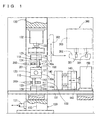
- Fig. 1 schematically shows a configuration of a resin-seal-molding apparatus for implementing the resin-seal-molding method of the present invention
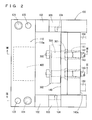
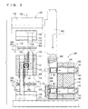
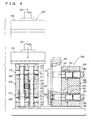
- Figs. 2-8 schematically show substantial part of a resin-seal-molding portion in the resin-seal-molding apparatus.
- Figs. 9-11 are explanatory views of a method of supply-setting a before-resin-seal-molding substrate to a prescribed position on the mold surface.
- Fig. 1 schematically shows an overall configuration of a resin-seal-molding apparatus.
- the resin-seal-molding apparatus includes a resin-seal-molding portion 100 for resin-seal-molding an electronic component on a substrate, a substrate supply-remove mechanism 200 for carry-supplying the before-resin-seal-molding substrate to a prescribed position, which will be described later, of the resin-seal-molding portion and for removing and carrying the resin-seal-molded substrate out of the resin-seal-molding portion, and a resin material carry-supply mechanism 300 for carry-supplying the resin material to a prescribed position, which will be described later, of the resin-seal-molding portion.
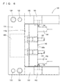
- Resin-seal-molding portion 100 includes mold 110 for resin-seal-molding an electronic component, a mold open-close mechanism 120 for opening and clamping the mold, a press frame mechanism 130 for applying prescribed clamping pressure to mold 110 in a state where mold 110 is clamped, a pot block 140 for supplying a resin material arranged beside mold 110, and a mechanism 150 for reciprocate driving the pot block arranged so that pot block 140 is freely joined and separated with respect to side position 110a of the mold intersecting perpendicularly with mold face (PL face) of mold 110.
- Mold 110 includes at least one set of mold structure unit.
- the drawing shows an example of a configuration in which two sets of mold structure units each constituted of a first mold 111 and a second mold 112 are arranged as stacked in the vertical direction.
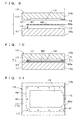
- a supply-set surface 113 for supplying substrate 400 is provided.
- Supply-set surface 113 implements a portion for supplying a single substrate for supply-setting one substrate 400 with an electronic component (not shown) mounted thereon.
- a step or the like for positioning the substrate is not provided, which have been provided as a recessed shape in a conventional mold surface.
- supply-set surface 113 for supplying the substrate is formed in a flat shape.
- a resin-molding cavity 114 is provided to the mold surface of second mold 112 arranged opposite to supply-set surface 113 of first mold 111.
- Reference number 115 in Figs. 9-11 denotes a transfer path for a molten resin material. One end thereof is formed to communicate with cavity 114, while the other end thereof is formed to communicate with side position 110a of mold face (PL face).
- Reference number 116 denotes a positioning pin provided at a prescribed position on the mold surface (substrate supply-set surface 113) of first mold 111.
- reference number 117 denotes a pin hole formed at each position on second mold 112 opposite to each positioning pin 116.
- Positioning pin 116 and pin hole 117 show one example of means for supply-setting before-resin-seal-molding substrate 400 to a prescribed position on substrate supply-set surface 113.
- substrate 400 when supply-setting substrate 400 to substrate supply-set surface 113, substrate 400 can efficiently and surely be supplied to a prescribed position on substrate supply-set surface 113 if a positioning hole 401 provided to substrate 400 and positioning pin 116 are engaged with each other. Further, performing clamping where two molds (111, 112) are closed in this state, each positioning pin 116 of first mold 111 is fitted into each pin hole 117 of second mold 112. Thus, as shown in Fig. 10, substrate 400 is surely supply-set to substrate supply-set surface 113.
- the prescribed position on substrate supply-set surface 113 to which substrate 400 is supply-set means a position where end portion 400a of substrate 400 and side position 110a of the mold are positioned on the identical plane. Formation of a gap between them is prevented by positioning end portion 400a of the substrate and side position 110a of the mold on the identical plane in clamping.
- an adverse effect can be prevented that the molten resin material with which the gap is filled remains and cure-molded. Further, such an adverse effect can efficiently and surely be prevented that part of the molten resin material in the gap flows onto the bottom surface of the substrate and resulting in formation of a resin flash on the substrate surface.
- transfer path 115 for the molten resin material is formed. Therefore, an air vent (not shown) communicating with cavity 114 may be formed at a position opposite to transfer path 115 relative to cavity 114.
- an air vent (not shown) communicating with cavity 114 may be formed at a position opposite to transfer path 115 relative to cavity 114.
- Mold open-close mechanism 120 is a mechanism for simultaneous mold-opening or clamping of the two sets of mold structure units (molds 110) arranged as stacked (overlaid) in the vertical direction.
- this mechanism an appropriate fluid power mechanism, crank mechanism or other mechanic and electric vertical drive mechanism can be employed.
- the drawing shows a mold open-close mechanism where a rack-pinion mechanism is employed.
- Body 121 of the mold open-close mechanism is provided with a pinion gear 122 provided to be rotated by a normal/reverse rotation drive motor (not shown), and two rack gears (123, 124) meshing with pinion gear 122 and move reversely to each other in the vertical direction based on the normal and reverse rotation of pinion gear 122.
- One rack gear 123 has its lower end portion fixed to a machine frame 101 fixed at a lower position, and has its upper end portion meshed with pinion gear 122.
- the other rack gear 124 has its lower end portion meshed with pinion gear 122, and has its upper end portion fixed to a mold mounting block 125 arranged above.
- One set of mold structure unit (mold 110) constituted of first mold 111 and second mold 112 is provided to each position of the upper surface and the lower surface of mold open-close mechanism body 121.
- first mold 111 thereof is fixed to the upper surface of mold open-close mechanism body 121
- second mold 112 is fixed to the lower surface of mold mounting block 125 arranged above.
- second mold 112 thereof is fixed to the lower surface of mold open-close mechanism body 121
- first mold 111 is fixed to the upper surface of mold mounting block 126 provided to machine frame 101.
- Mold open-close mechanism 120 in the present embodiment is capable of simultaneously mold-open or clamp the two sets of mold structure units (molds 110) arranged as stacked in the vertical direction by rotating pinion gear 122 by a motor and moving rack gears (123, 124) meshed with pinion gear 122 reversely to each other in the vertical direction.
- the mold open-close mechanism of the present invention is not limited to such a mold open-close mechanism, and other configuration can be employed. That is, the mold open-close mechanism of the present invention may only be a mechanism that can simultaneously mold-open or clamp two sets of mold structure units (molds 110) arranged as stacked in the vertical direction.
- the aforementioned appropriate fluid power mechanism, crank mechanism or other mechanic and electric vertical drive mechanism can be employed as a drive source thereof.
- a configuration may be employed wherein such a drive source moves second mold 112 itself (or the rack gear) vertically, and the two sets of mold structure units (molds 110) arranged as stacked in the vertical direction can simultaneously mold-opened or clamped in association therewith.
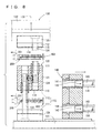
- Press frame mechanism 130 is for applying prescribed clamping pressure to mold 110 in a state where mold 110 is clamped.
- Press frame mechanism 130 is provided so that it can reciprocally move along machine frame 101 by an appropriate reciprocate drive mechanism 131.
- Press frame mechanism 130 is provided with press means 132 using electric, hydraulic, mechanic and other appropriate pressing mechanism.
- center position 118 of mold 110 refers to the center position of mold 110 itself.
- the center position of mold 110 in this case means the center position of the substrate at which clamping pressure can efficiently be applied to substrate 400.
- the present embodiment shows the mechanism where molds 110 are fixed to machine frame 101. Therefore, press frame mechanism 130 reciprocates along machine frame 101 (see Fig. 1). It is noted that the relationship between them is relative.
- a configuration which is reverse of the configuration shown in the drawing, that is, the configuration where the position of press frame mechanism 130 is fixed and molds 110 reciprocate may be employed.
- press means 132 and mold 110 are separated in order to implement the above-described relative movement. It is noted that they (132, 125) may be fixed after the above-described center-alignment adjustment is finished. In this case, there is an advantage that, as the center-alignment adjustment is finished already, press means 132 can be used as a vertical drive mechanism for simultaneously mold-opening or clamping the two sets of mold structure units (molds 110) arranged as stacked, effectively using the movement of press means 132 in its vertical direction.
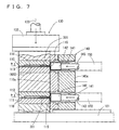
- Pot block 140 is arranged beside molds 110, and provided so that it is freely joined and separated with respect to side position 110a of the mold intersecting perpendicularly with mold face (PL face) of mold 110 by reciprocate drive mechanism 150.
- Pot block 140 is provided with a pot 141 for supplying a resin material arranged corresponding to the number of the vertical two sets of mold structure units (molds 110) and their arrangement position, a plunger 142 for pressurizing the resin material supplied inside pot 141, and a reciprocate drive mechanism 143 for causing plunger 142 to reciprocate.
- a stopper mechanism 103 is arranged for more surely maintaining joined state when pot block 140 is joined with side position 110a of the mold intersecting perpendicularly with mold face (PL face) of mold 110.
- Stopper mechanism 103 is provided with a stopper member 104 joining with a back surface 140a of pot block 140 joined with mold 110, so as to press and stop back surface 140a against side position 110a of mold 110.
- an appropriate heater (not shown) for heating and melting resin material 301 supplied inside pot 141 is inserted.
- the whole pot block 140 can be advanced to be joined with the position where mold face of mold 110 and side position 110a intersect, and can be retracted to be separated from this position. Further, retracting plunger 142 by the other reciprocate mechanism 143, a space for supplying resin material 301 in a portion of pot 141 (see Fig. 3) can be formed. Advancing plunger 142 from this position, resin material 301 supplied to pot 141 can be pressurized.
- a space formed by first mold 111 and second mold 112 in the mold structure unit and pot 141 in pot block 140 with each other can be communicated with each other.
- the heater and pressurizing resin material 301 with plunger 142 By heating and melting resin material 301 in pot 141 by the heater and pressurizing resin material 301 with plunger 142, through transfer path 115, the molten resin material in pot 141 can directly be injected so that cavity 114 is filled therewith.
- substrate supply-remove mechanism 200 can carry before-resin-seal-molding substrate 400 to a prescribed position in resin-seal-molding portion 100, that is, between first mold 111 and second mold 112 in each of the vertical two sets of mold structure units as mold-opened.
- Substrate supply-remove mechanism 200 can supply-set substrate 400 to substrate supply-set surface 113 of first mold 111.
- substrate supply-remove mechanism 200 stops resin-seal-molded substrate 402 (resin-seal-molded product) using the stop mechanism and removes it from substrate supply-set surface 113 as mold-opened after resin-seal-molding.
- Substrate supply-remove mechanism 200 is provided so that it can carry substrate 402 to the outside from between first mold 111 and second mold 112 in each of the vertical two sets of mold structure units and transfer it to an apparatus where the next process is performed.
- before-resin-seal-molding substrate 400 can be supply-set to a prescribed position in resin-seal-molding portion 100 and resin-seal-molded substrate 402 can be removed to the outside of resin-seal-molding portion 100.
- Resin material carry-supply mechanism 300 is provided so that it can supply resin material 301 accommodated in a resin material accommodating portion 303 to a prescribed position in resin-seal-molding portion 100 using a resin material carry-supply member 302, that is, to a space provided to the opening-front end of pot 141 when pot block 140 and plunger 142 are retracted to a prescribed position (see Figs. 1-4).
- Resin material carry-supply member 302 is provided with holes 304 for feeding the resin material arranged corresponding to the number of the vertical two sets of mold structure units (molds 110) and their arrangement position, and extrude members 305 for extruding resin material 301 fed in holes 304 to supply it into pot 141.
- Resin-seal-molding of an electronic component in the above embodiment is carried out as follows, for example.
- substrate supply-remove mechanism 200 carries before-resin-seal-molding substrate 400 to between first mold 111 and second mold 112, and supply-sets substrate 400 to substrate supply-set surface 113 of first mold 111.
- reciprocate drive mechanism 150 retracts the entire pot block 140 from the position of mold 110.
- Reciprocate drive mechanism 143 retracts plunger 142 to form a space for supplying resin material 301 in the opening-front end of pot 141.
- mold open-close mechanism 120 clamps the vertical two sets of mold structure units (molds 110).
- reciprocate drive mechanism 131 performs alignment adjustment of moving press center position 133 of press means 132 in press frame mechanism 130 to a position where it matches with center position 118 of mold 110 (see Fig.1). Reciprocate drive mechanism 131 applies pressing force of press means 132 to center position 118 of clamped mold 110. Thus, reciprocate drive mechanism 131 applies clamping force of press means 132 to each of the mold structure units (molds 110) arranged as stacked simultaneously and uniformly (see Fig. 4). Resin material carry-supply member 302 supplies resin material 301 accommodated in a resin material accommodating portion 303 into the space of pot 141 (see Figs. 1, 3 and 4).
- reciprocate drive mechanism 150 joins pot block 140 with side position 110a of the mold intersecting perpendicularly with mold face (PL face) of mold 110.
- Reciprocate drive mechanism 150 joins stopper member 104 in stopper mechanism 103 with back surface 140a of pot block 140, to stop back surface 140a against side position 110a of mold 110 in a state being pressed.
- the mold face of first mold 111 and second mold 112 in the mold structure unit (mold 110) and pot 141 in pot block 140 communicate with each other, and resin material 301 supplied inside pot 141 is heated and melted by the heater.
- the stop mechanism of substrate supply-remove mechanism 200 stops resin-seal-molded substrate 402 (resin-seal-molded product) and removes substrate 402 from substrate supply-set surface 113 as mold-opened, and carries substrate 400 to outside and transfers it to a position of an apparatus where the next process is carried out.
- the apparatus for resin-seal-molding an electronic component shown in the present embodiment includes simply structured mold, and therefore the operability or workability thereof can be improved. This facilitates practical application of the apparatus.
- resin flash formation on the substrate surface can efficiently and surely be prevented without being affected by the variation in the thickness of a substrate. Therefore, a resin-seal-molded product of an electronic component of high quality and high reliability can be molded.
- a simple structure can be employed for the resin-seal-molding apparatus. Therefore, the shape of the overall apparatus can be made small. Further, the maintenance works of the mold can be carried out easily. Still further, the wasted resin amount can be suppressed to thereby contribute to resource saving.
Landscapes
- Engineering & Computer Science (AREA)
- Manufacturing & Machinery (AREA)
- Mechanical Engineering (AREA)
- Encapsulation Of And Coatings For Semiconductor Or Solid State Devices (AREA)
- Injection Moulding Of Plastics Or The Like (AREA)
- Moulds For Moulding Plastics Or The Like (AREA)
Applications Claiming Priority (1)
| Application Number | Priority Date | Filing Date | Title |
|---|---|---|---|
| JP2005280294A JP2007095804A (ja) | 2005-09-27 | 2005-09-27 | 電子部品の樹脂封止成形方法及び装置 |
Publications (2)
| Publication Number | Publication Date |
|---|---|
| EP1768166A2 true EP1768166A2 (de) | 2007-03-28 |
| EP1768166A3 EP1768166A3 (de) | 2008-10-08 |
Family
ID=37663389
Family Applications (1)
| Application Number | Title | Priority Date | Filing Date |
|---|---|---|---|
| EP06254901A Pending EP1768166A3 (de) | 2005-09-27 | 2006-09-22 | Verfahren zur Kunstharzverkapselung elektronischer Bauelemente und zugehörige Vorrichtung |
Country Status (6)
| Country | Link |
|---|---|
| US (1) | US20070069422A1 (de) |
| EP (1) | EP1768166A3 (de) |
| JP (1) | JP2007095804A (de) |
| CN (1) | CN100511609C (de) |
| SG (1) | SG131059A1 (de) |
| TW (1) | TW200715429A (de) |
Cited By (2)
| Publication number | Priority date | Publication date | Assignee | Title |
|---|---|---|---|---|
| WO2023194649A1 (en) * | 2022-04-05 | 2023-10-12 | Ledil Oy | A system and a method for injection moulding |
| CN118952573A (zh) * | 2024-10-21 | 2024-11-15 | 江苏纽泰格科技集团股份有限公司 | 汽车注塑件注塑模具装置 |
Families Citing this family (5)
| Publication number | Priority date | Publication date | Assignee | Title |
|---|---|---|---|---|
| KR100897132B1 (ko) * | 2007-09-12 | 2009-05-14 | 삼성모바일디스플레이주식회사 | 표시패널 봉지장치 및 이를 이용한 유기전계발광표시장치의 제조방법 |
| KR101254860B1 (ko) * | 2008-09-30 | 2013-04-15 | 토와 가부시기가이샤 | 전자 부품의 압축 수지 밀봉 성형 방법 및 그를 위한 장치 |
| JP5385886B2 (ja) * | 2010-11-02 | 2014-01-08 | Towa株式会社 | 電気回路部品の樹脂封止成形方法及び装置 |
| JP6218549B2 (ja) * | 2013-10-17 | 2017-10-25 | Towa株式会社 | 半導体封止型への半導体基板供給方法及び半導体基板供給装置 |
| JP6320448B2 (ja) * | 2016-04-28 | 2018-05-09 | Towa株式会社 | 樹脂封止装置および樹脂封止方法 |
Family Cites Families (17)
| Publication number | Priority date | Publication date | Assignee | Title |
|---|---|---|---|---|
| JPS5775435A (en) * | 1980-10-29 | 1982-05-12 | Mitsubishi Electric Corp | Liquid transfer molding |
| JPH0350841A (ja) * | 1989-07-19 | 1991-03-05 | Toshiba Corp | 半導体樹脂封止用金型装置 |
| JPH05147062A (ja) * | 1991-11-28 | 1993-06-15 | Yamada Seisakusho Co Ltd | トランスフアモールド装置 |
| KR970002295B1 (ko) * | 1993-02-23 | 1997-02-27 | 미쯔비시 덴끼 가부시끼가이샤 | 성형방법 |
| TW257745B (de) * | 1993-07-22 | 1995-09-21 | Towa Kk | |
| JP2738361B2 (ja) * | 1995-09-13 | 1998-04-08 | 日本電気株式会社 | 樹脂モールド装置および樹脂モールド方法 |
| JPH11176852A (ja) * | 1997-12-12 | 1999-07-02 | Sony Corp | 半導体樹脂封止装置 |
| JP3450223B2 (ja) * | 1999-05-27 | 2003-09-22 | Necエレクトロニクス株式会社 | 半導体装置封入用金型、及び、半導体装置封入方法 |
| US6564447B1 (en) * | 2000-11-15 | 2003-05-20 | National Semiconductor Corporation | Non lead frame clamping for matrix leadless leadframe package molding |
| JP3711333B2 (ja) * | 2001-07-27 | 2005-11-02 | 沖電気工業株式会社 | 半導体装置の製造方法および樹脂封止装置 |
| US7281922B2 (en) * | 2002-03-27 | 2007-10-16 | Commerce Limited Partnership | Continuous pallet production apparatus |
| JP2004014823A (ja) * | 2002-06-07 | 2004-01-15 | Renesas Technology Corp | 半導体装置及びその製造方法 |
| JP4162474B2 (ja) * | 2002-11-26 | 2008-10-08 | Towa株式会社 | 樹脂成形用金型への供給方法、樹脂成形用金型からの取出方法、供給機構、及び、取出機構 |
| NL1022323C2 (nl) * | 2003-01-08 | 2004-07-09 | Fico Bv | Inrichting en werkwijze voor het met omhulmateriaal omhullen van een op een drager bevestigde elektronische component. |
| JP4607429B2 (ja) * | 2003-03-25 | 2011-01-05 | 東レ・ダウコーニング株式会社 | 半導体装置の製造方法および半導体装置 |
| JP4153862B2 (ja) * | 2003-10-24 | 2008-09-24 | 第一精工株式会社 | 半導体樹脂封止用金型 |
| JP4084844B2 (ja) * | 2005-09-27 | 2008-04-30 | Towa株式会社 | 電子部品の樹脂封止成形方法及び装置 |
-
2005
- 2005-09-27 JP JP2005280294A patent/JP2007095804A/ja active Pending
-
2006
- 2006-09-12 SG SG200606305-1A patent/SG131059A1/en unknown
- 2006-09-14 TW TW095134016A patent/TW200715429A/zh unknown
- 2006-09-20 US US11/523,715 patent/US20070069422A1/en not_active Abandoned
- 2006-09-22 EP EP06254901A patent/EP1768166A3/de active Pending
- 2006-09-26 CN CNB2006101413793A patent/CN100511609C/zh not_active Expired - Fee Related
Cited By (2)
| Publication number | Priority date | Publication date | Assignee | Title |
|---|---|---|---|---|
| WO2023194649A1 (en) * | 2022-04-05 | 2023-10-12 | Ledil Oy | A system and a method for injection moulding |
| CN118952573A (zh) * | 2024-10-21 | 2024-11-15 | 江苏纽泰格科技集团股份有限公司 | 汽车注塑件注塑模具装置 |
Also Published As
| Publication number | Publication date |
|---|---|
| US20070069422A1 (en) | 2007-03-29 |
| TW200715429A (en) | 2007-04-16 |
| CN1941306A (zh) | 2007-04-04 |
| SG131059A1 (en) | 2007-04-26 |
| JP2007095804A (ja) | 2007-04-12 |
| CN100511609C (zh) | 2009-07-08 |
| EP1768166A3 (de) | 2008-10-08 |
Similar Documents
| Publication | Publication Date | Title |
|---|---|---|
| JP5934139B2 (ja) | 樹脂封止装置及び樹脂封止方法 | |
| JP6151610B2 (ja) | モールド金型及び樹脂モールド装置並びに樹脂モールド方法 | |
| US20070069421A1 (en) | Method of resin-seal-molding electronic component and apparatus therefor | |
| EP1768166A2 (de) | Verfahren zur Kunstharzverkapselung elektronischer Bauelemente und zugehörige Vorrichtung | |
| CN112677422B (zh) | 树脂成形品的制造方法及树脂成形装置 | |
| US20070072346A1 (en) | Method of resin-seal-molding electronic component and apparatus therefor | |
| WO2008041431A1 (en) | Method for resin seal molding, and resin seal molding apparatus for use in the method | |
| KR100991625B1 (ko) | 수지 밀봉 장치 및 수지 밀봉 방법 | |
| JP4886344B2 (ja) | 電子部品の樹脂封止成形装置 | |
| KR100815013B1 (ko) | 전자부품의 수지밀봉 성형 방법 및 장치 | |
| JP4771812B2 (ja) | 射出成形体の成形方法、並びに射出成形装置 | |
| KR100815014B1 (ko) | 전자부품의 수지밀봉 성형 방법 및 장치 | |
| KR100822523B1 (ko) | 전자부품의 수지밀봉 성형 방법 및 장치 | |
| JP2007281363A (ja) | 電子部品の樹脂封止成形方法及び装置 | |
| JP2007281364A (ja) | 電子部品の樹脂封止成形方法及び装置 | |
| KR100340979B1 (ko) | 전자부품의수지봉지성형방법 | |
| JP4509198B2 (ja) | 樹脂封止装置および樹脂封止方法 | |
| JP2004014936A (ja) | 封止成形装置 | |
| JPH03180310A (ja) | 電子部品の樹脂封止成形用金型 | |
| JP2007288110A (ja) | 樹脂封止型及び樹脂封止方法 | |
| JP2007281367A (ja) | 電子部品の樹脂封止成形装置 | |
| JP2007281366A (ja) | 電子部品の樹脂封止成形装置 | |
| JP2007281365A (ja) | 電子部品の樹脂封止成形方法及び装置 |
Legal Events
| Date | Code | Title | Description |
|---|---|---|---|
| PUAI | Public reference made under article 153(3) epc to a published international application that has entered the european phase |
Free format text: ORIGINAL CODE: 0009012 |
|
| AK | Designated contracting states |
Kind code of ref document: A2 Designated state(s): AT BE BG CH CY CZ DE DK EE ES FI FR GB GR HU IE IS IT LI LT LU LV MC NL PL PT RO SE SI SK TR |
|
| AX | Request for extension of the european patent |
Extension state: AL BA HR MK YU |
|
| PUAL | Search report despatched |
Free format text: ORIGINAL CODE: 0009013 |
|
| AK | Designated contracting states |
Kind code of ref document: A3 Designated state(s): AT BE BG CH CY CZ DE DK EE ES FI FR GB GR HU IE IS IT LI LT LU LV MC NL PL PT RO SE SI SK TR |
|
| AX | Request for extension of the european patent |
Extension state: AL BA HR MK RS |
|
| AKX | Designation fees paid | ||
| REG | Reference to a national code |
Ref country code: DE Ref legal event code: 8566 |
|
| STAA | Information on the status of an ep patent application or granted ep patent |
Free format text: STATUS: THE APPLICATION IS DEEMED TO BE WITHDRAWN |