EP1768353A2 - Procédé et système pour l'identification visuelle et spatiale d'un appeleur - Google Patents
Procédé et système pour l'identification visuelle et spatiale d'un appeleur Download PDFInfo
- Publication number
- EP1768353A2 EP1768353A2 EP06076761A EP06076761A EP1768353A2 EP 1768353 A2 EP1768353 A2 EP 1768353A2 EP 06076761 A EP06076761 A EP 06076761A EP 06076761 A EP06076761 A EP 06076761A EP 1768353 A2 EP1768353 A2 EP 1768353A2
- Authority
- EP
- European Patent Office
- Prior art keywords
- caller identification
- identification information
- visual indicator
- original
- spatial
- Prior art date
- Legal status (The legal status is an assumption and is not a legal conclusion. Google has not performed a legal analysis and makes no representation as to the accuracy of the status listed.)
- Withdrawn
Links
Images


Classifications
-
- H—ELECTRICITY
- H04—ELECTRIC COMMUNICATION TECHNIQUE
- H04M—TELEPHONIC COMMUNICATION
- H04M1/00—Substation equipment, e.g. for use by subscribers
- H04M1/247—Telephone sets including user guidance or feature selection means facilitating their use
- H04M1/2474—Telephone terminals specially adapted for disabled people
- H04M1/2475—Telephone terminals specially adapted for disabled people for a hearing impaired user
-
- H—ELECTRICITY
- H04—ELECTRIC COMMUNICATION TECHNIQUE
- H04M—TELEPHONIC COMMUNICATION
- H04M1/00—Substation equipment, e.g. for use by subscribers
- H04M1/57—Arrangements for indicating or recording the number of the calling subscriber at the called subscriber's set
- H04M1/575—Means for retrieving and displaying personal data about calling party
-
- H—ELECTRICITY
- H04—ELECTRIC COMMUNICATION TECHNIQUE
- H04M—TELEPHONIC COMMUNICATION
- H04M19/00—Current supply arrangements for telephone systems
- H04M19/02—Current supply arrangements for telephone systems providing ringing current or supervisory tones, e.g. dialling tone or busy tone
- H04M19/04—Current supply arrangements for telephone systems providing ringing current or supervisory tones, e.g. dialling tone or busy tone the ringing-current being generated at the substations
- H04M19/041—Encoding the ringing signal, i.e. providing distinctive or selective ringing capability
-
- H—ELECTRICITY
- H04—ELECTRIC COMMUNICATION TECHNIQUE
- H04M—TELEPHONIC COMMUNICATION
- H04M3/00—Automatic or semi-automatic exchanges
- H04M3/02—Calling substations, e.g. by ringing
-
- H—ELECTRICITY
- H04—ELECTRIC COMMUNICATION TECHNIQUE
- H04M—TELEPHONIC COMMUNICATION
- H04M3/00—Automatic or semi-automatic exchanges
- H04M3/42—Systems providing special services or facilities to subscribers
- H04M3/42391—Systems providing special services or facilities to subscribers where the subscribers are hearing-impaired persons, e.g. telephone devices for the deaf
-
- H—ELECTRICITY
- H04—ELECTRIC COMMUNICATION TECHNIQUE
- H04M—TELEPHONIC COMMUNICATION
- H04M1/00—Substation equipment, e.g. for use by subscribers
- H04M1/72—Mobile telephones; Cordless telephones, i.e. devices for establishing wireless links to base stations without route selection
- H04M1/724—User interfaces specially adapted for cordless or mobile telephones
- H04M1/72475—User interfaces specially adapted for cordless or mobile telephones specially adapted for disabled users
- H04M1/72478—User interfaces specially adapted for cordless or mobile telephones specially adapted for disabled users for hearing-impaired users
-
- H—ELECTRICITY
- H04—ELECTRIC COMMUNICATION TECHNIQUE
- H04M—TELEPHONIC COMMUNICATION
- H04M19/00—Current supply arrangements for telephone systems
- H04M19/02—Current supply arrangements for telephone systems providing ringing current or supervisory tones, e.g. dialling tone or busy tone
- H04M19/04—Current supply arrangements for telephone systems providing ringing current or supervisory tones, e.g. dialling tone or busy tone the ringing-current being generated at the substations
- H04M19/048—Arrangements providing optical indication of the incoming call, e.g. flasher circuits
Definitions
- the present invention relates to visual signaling and, more particularly, to visually signaling discernible information to persons more reliant on visual indications, such as hearing-impaired persons.
- One such device that has traditionally relied upon an audible indicator is a telephone or similar telecommunications device. Such devices have conventionally utilized a bell or other ringing device for notification to a user of an incoming call.
- visual indicators For hearing-impaired users, or in environments that are not conducive to audible indicator detection, visual indicators have been developed.
- One known visual indication approach utilized by hearing-impaired users for identifying an incoming telephone call is illustrated with reference to FIG. 1. This prior approach connects a telephone 100 through a coupling circuit 102 to a room lamp 104 or other light source.
- the coupling circuit 102 upon detection of a telephone "ring" signal on the network 106, causes, for example, a room light or lamp 104 to flash repeatedly when a ringing voltage or other signal designates an incoming call.
- Flashers In such applications and to the hearing-impaired community, telephone-coupling circuits and single light source visual indicator have come to be known as "flashers.” Flashers or visual indicators may be implemented as a single light source located on or near the telephone or may be coupled to a more generally present light source such as a light bulb or lamp in a room inhabited by a hearing-impaired user. While such visual indicators provide notification to a user thereof, such visual indicators are informationally "one dimensional" in that they provide only a notification of the occurrence of an event (i.e., the ringing of an incoming call).
- FIG. 2 illustrates a conventional telephone 120 configured with a caller identification display 122 that provides a visual notification of an incoming call and even provides information correlated to the calling party.
- the caller identification display 122 is configured to provide correlated information of the calling party but is not adequately visually alerting to draw attention to the telephone device. Therefore, there is a need to provide an adequately visually alerting mechanism further configured to provide more information to a hearing-impaired user through a visual indicator.
- a caller identification visual alerting device includes incoming caller identification logic configured to capture current caller identification information from an incoming call.
- a stored caller identification list is configured to store a plurality of entries of reference caller identification information and a corresponding respective plurality of entries of spatial visual indicator patterns.
- the reference caller identification information is matched with the current caller identification information.
- the caller identification visual alerting device further includes a spatial visual indicator configured to activate a plurality of illuminatable elements according to one of the plurality of spatial visual indicator patterns corresponding to one of the plurality of reference caller identification information when matched to the current caller identification information.
- a visual caller identification telephone in another embodiment, includes a telephone transceiver configured to receive an incoming call and a caller identification visual alerting device.
- the caller identification visual alerting device includes incoming caller identification logic configured to capture current caller identification information from an incoming call and a stored caller identification list configured to store a plurality of entries of reference caller identification information and a corresponding respective plurality of entries of spatial visual indicator patterns.
- the reference caller identification information is matched with the current caller identification information and the spatial visual indicator patterns are uncorrelated to the reference caller identification information.
- the visual caller identification telephone further includes a spatial visual indicator configured to activate a plurality of illuminatable elements according to one of the plurality of spatial visual indicator patterns corresponding to one of the plurality of reference caller identification information when matched to the current caller identification information.
- a method of indicating an incoming call is provided.
- Current caller identification information is captured from the incoming call and compared with a stored caller identification list configured to store therein a plurality of entries of reference caller identification information and a corresponding respective plurality of entries of spatial visual indicator patterns.
- a plurality of illuminatable elements is activated according to the spatial visual indicator patterns.
- FIG. 1 illustrates a conventional telephone flasher, in accordance with the prior art
- FIG. 2 illustrates conventional caller identification on a telephone device, in accordance with the prior art
- FIG. 3 illustrates a two dimensional visual indicator configured to provide a visual indication and convey information indicative of the specific activation of the device, in accordance with one embodiment of the present invention
- FIG. 4 illustrates a two dimensional visual indicator configured to provide a visual indication and convey information indicative of the specific activation of the device, in accordance with another embodiment of the present invention
- FIG. 5 is a block diagram of a communication system including a visual indicator telephone system, in accordance with an embodiment of the present invention.
- FIG. 6 is a functional block diagram of a visual indicator telephone system, in accordance with an embodiment of the present invention.
- FIG. 7 is a detailed diagram of exemplary data elements within a caller identification list, in accordance with an embodiment of the present invention.
- FIG. 3 illustrates a visual indicator telephone system, in accordance with an embodiment of the present invention.
- visual indicators for conventionally audible indicating devices provide utility to hearing-impaired individuals who are physically incapable of detecting audible sounds and to individuals in a noisy work environment.
- a visual indicator telephone system 200 includes general telephony capability illustrated herein as a telephone 202.
- Telephone 202 facilitates full duplex conversation between a calling party and a called party.
- telephone 202 may be configured as a conventional telephone while in a separate embodiment, telephone 202 may be configured as a videophone for facilitating an exchange of sign language or other hearing-impaired signaling techniques. It should be noted that while the utility and application of the various embodiments of the present invention are described with reference to a hearing-impaired environment, the invention also finds application to any environment where a visual indicator may be helpful or desirable.
- the visual indictor telephone system 200 may be connected to various types of communication networks 204, examples of which include a public switched telephone network (PSTN) as well as data networks such as an IP network. Also coupled to the network 204 is a spatial visual indicator device 206 configured to identify an incoming call and correlate the incoming current caller identification information with entries in a stored caller identification list.
- the stored caller identification list is configured to store a plurality of entries of reference caller identification information and a corresponding respective plurality of entries of spatial visual indicator patterns which are uncorrelated to the incoming current caller identification information.
- the spatial visual indicator patterns are mapped or assigned to reference caller identification information but the spatial visual indicator patterns do not render a specific visual pattern that contains the information of the current caller identification information.
- the spatial visual indicator device 206 When the spatial visual indicator device 206 detects a match between the current caller identification information and one of the plurality of entries of reference caller identification information, the spatial visual indicator device 206 activates a spatial visual indicator 208 including a plurality of illuminatable elements 210 according to one of the plurality of spatial visual indicator patterns corresponding to one of the plurality of reference caller identification information.
- the spatial visual indicator patterns are selected to correspond to different stored reference caller identification information but the patterns are not correlated to the current caller identification information.
- the reference caller identification information identifies, for example, a telephone number or IP address assigned to the party initiating the call (i.e., the calling party) but the spatial visual indicator device 206 does not merely display the telephone number or IP address as is typical with conventional "caller id.”
- the entries of reference caller identification information have associated thereto visual patterns (e.g., chaser, blinking, strobing, flashing, etc.) that correspond or have been linked to specific ones of the stored or programmed reference caller identification information.
- a current caller identification X may be received by the spatial visual indicator device 206 and correlate to a stored reference caller identification information X but the linked spatial visual indicator pattern may be a "chaser pattern of a fast cadence" where all of the illuminatable elements 210 are activated with the exception of one unilluminated element which is selected in a spinning sequence at a "fast" rate or cadence.
- the various embodiments of the present invention find application to a visual caller identification methodology for "frequent" or "preferred” callers that may be readily visually identified by a user from a visual indicator that may be configured to present a more startling or alerting visual indicator than an alphanumeric readout that is generally unobtrusive and therefore requires more direct monitoring by a user to determine if in incoming call is detected.
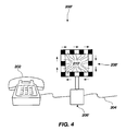
- FIG. 4 illustrates a visual indicator telephone system, in accordance with another embodiment of the present invention.
- a visual indicator telephone system 200' including telephone 202 as described hereinabove.
- a spatial visual indicator device 206' coupled to the network 204 is a spatial visual indicator device 206' configured to identify an incoming call and correlate the incoming current caller identification information with entries of reference caller identification information stored in a caller identification list (FIG. 6).
- the visual indicator telephone system 200' further includes a spatial visual indicator 208' including a plurality of illuminatable elements 210' which may be activated according to one of the plurality of spatial visual indicator patterns corresponding to one of the plurality of reference caller identification information.
- the plurality of illuminatable elements 210' may be configured as part of an integrated display, such as a monitor or other array of display elements with the illuminatable elements 210' being configured as a grouping of lights or pixels that may be dedicated or shared for other display purposes.
- the programming to share access to illuminatable elements is understood by those of ordinary skill in the art.
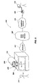
- FIG. 5 is a block diagram of a communication system including a visual indicator telephone system, in accordance with an embodiment of the present invention.
- the illustrated communication system is specifically drawn to facilitate a communication session between a hearing-impaired user and a hearing-capable user, but such an example is exemplary and is not to be considered as limiting.
- a communication system 310 enables a user 314 (e.g., a hearing-impaired user) to engage in conversation through the communication system 310 with a user 316 (e.g., a hearing-capable user).
- the hearing-impaired user 314 may exhibit varying levels of impairment including a voice-capable hearing-impaired user or a voice-incapable hearing-impaired user.
- the voice capability of a hearing-impaired user may be used to determine the extent of translation or relay services relied upon during a communication session within communication system 310.
- a communication session between the users is facilitated through the use of various equipments, which are preferably coupled together using one or more networks including a telephone network such as the Public Switch Telephone Network (PSTN) and/or data networks such as Wide Area Networks, an example of which is the Internet.
- PSTN Public Switch Telephone Network
- data networks such as Wide Area Networks
- use of the term "telephone network” as used herein also contemplates networks which are compatible and configured to provide communications using digital standards, an example of which includes Voice over Internet Protocol (VoIP).
- VoIP Voice over Internet Protocol
- interpretive services e.g., relay services
- interpretive services e.g., relay services
- the hearing-impaired user is voice-incapable, then communication with the interpreter occurs primarily through the use of sign language. If the hearing-impaired user is predominantly voice-capable, then communication with the interpreter may be performed by the users expressing themselves through voice signals and "hearing" the interpreter through the use of sign language or other text-based interfaces.
- the sign language images are translated or interpreted by a relay service 320 providing a level of relay service herein defined as a "video relay service.”
- a relay service 320 providing a level of relay service herein defined as a "video relay service.”
- the sign language images are translated by the relay service 320 they are forwarded as voice information over a voice-based communication connection to the hearing-capable user 316.
- One means for relaying the communicative expressions of a voice-incapable hearing-impaired user 314 within the communication system 310 incorporates the visual indicator telephone system 312, an example of which includes a video phone 330 and a spatial visual indicator device 206 which further includes a spatial visual indicator 208.
- the visual indicator telephone system receives the current caller identification information from one or more networks 317, 318 and indicates an incoming call.
- the spatial visual indicator device 206 captures the current caller identification information from the incoming call and compares the information with entries in a stored caller identification list (FIG. 6) to determine if a match with reference caller identification information exists.
- the stored caller identification list is configured to store a plurality of entries of reference caller identification information and a corresponding respective plurality of entries of spatial visual indicator patterns.
- the spatial visual indicator patterns are uncorrelated to the current caller identification information.
- the spatial visual indicator 208 is activated causing a plurality of illuminatable elements to flash or illuminate according to one of the plurality of spatial visual indicator patterns corresponding to one of the plurality of reference caller identification information.
- the visual indicator telephone system 312 captures and displays, in video form, the communicative expressions exhibited by the voice-incapable hearing-impaired user 314.
- the visual indicator telephone system 312 forwards voice communicative expressions exhibited by the voice-capable hearing-impaired user 314 to the relay service and directly to the hearing-capable user 316.
- the sign language and/or body language may be interpreted or translated by relay service 320.
- the hearing-capable user 316 interacts in a conventional manner with relay service 320 through the use of voice-based dialog conveyed over a conventional voice phone 322.
- the various devices are coupled to relay service 320 using one or more networks 317, 318.
- networks 317, 318 may be implemented according to the standards and bandwidth requirements of voice phone 322 and, as stated, may further be implemented according to digital telephony standards including VOIP.
- FIG. 6 is a functional block diagram of a visual indicator telephone system, in accordance with an embodiment of the present invention.
- a visual indicator telephone system 200 is configured for coupling with a network 204, an example of which includes PSTN and IP-based networks.
- Visual indicator telephone system 200 includes general telephony capability illustrated herein as a telephone 202.
- Telephone 202 facilitates full duplex conversation between a calling party and a called party.
- telephone 202 may be configured as a conventional telephone while in a separate embodiment, telephone 202 may be configured as a videophone for facilitating an exchange of sign language or other hearing-impaired signaling techniques.
- Visual indicator telephone system 200 further includes a spatial visual indicator device 206 which further includes incoming call detection logic 350 and control logic 352 configured to identify an incoming call.
- Spatial visual indictor device 206 further includes incoming caller identification logic 354 configured to correlate the incoming current caller identification information 356 with entries in a stored caller identification list 358 retained in storage 360.
- the stored caller identification list 358 is configured to store a plurality of entries of reference caller identification information 362 and a corresponding respective plurality of entries of spatial visual indicator patterns 364 which are uncorrelated to the incoming current caller identification information 356.
- the spatial visual indicator patterns 364 are mapped or assigned to reference caller identification information 364 but the spatial visual indicator patterns do not render a specific visual pattern that contains the information of the current caller identification information.
- the spatial visual indicator device 206 When the spatial visual indicator device 206 detects a match between the current caller identification information and one of the plurality of entries of reference caller identification information, the spatial visual indicator device 206 activates a spatial visual indicator 208 including a plurality of illuminatable elements 210 (FIGS. 3-4) according to one of the plurality of spatial visual indicator patterns 364 corresponding to one of the plurality of reference caller identification information 362.
- the visual indicator telephone system 200 may further include an audio indicator 366 which receives a unique signal such as the spatial visual indicator pattern for generating a unique audio pattern in conjunction with the display of the mapped spatial visual indicator pattern 364 corresponding to an assigned to reference caller identification information 362. Supplementing the expression of the spatial visual indicator with a corresponding audio indicator may augment the sensory perception of a partially hearing-impaired user or may also supplement call notification for a mixed hearing-impaired and hearing-capable environment.
- an audio indicator 366 which receives a unique signal such as the spatial visual indicator pattern for generating a unique audio pattern in conjunction with the display of the mapped spatial visual indicator pattern 364 corresponding to an assigned to reference caller identification information 362. Supplementing the expression of the spatial visual indicator with a corresponding audio indicator may augment the sensory perception of a partially hearing-impaired user or may also supplement call notification for a mixed hearing-impaired and hearing-capable environment.
- FIG. 7 is a detailed diagram of exemplary data elements within a caller identification list, in accordance with an embodiment of the present invention.
- the stored caller identification list 358 is configured to store a plurality of entries of reference caller identification information 362 and a corresponding respective plurality of entries of spatial visual indicator patterns 364 which are uncorrelated to the incoming current caller identification information 356.
- the spatial visual indicator patterns 364 are mapped or assigned to reference caller identification information 362 but the spatial visual indicator patterns do not render a specific visual pattern that contains the information of the current caller identification information. Examples of spatial visual indicator patterns 364 include alerting patterns that are visually distinguishable according to various factors such as strobe rate, rotation or chasing rate, ratio of on and off illuminatable elements, relational position of on and off illuminatable elements, etc.
Landscapes
- Engineering & Computer Science (AREA)
- Signal Processing (AREA)
- Physics & Mathematics (AREA)
- Health & Medical Sciences (AREA)
- Acoustics & Sound (AREA)
- Otolaryngology (AREA)
- Computer Vision & Pattern Recognition (AREA)
- Human Computer Interaction (AREA)
- Telephone Function (AREA)
- Telephonic Communication Services (AREA)
Applications Claiming Priority (1)
| Application Number | Priority Date | Filing Date | Title |
|---|---|---|---|
| US11/233,612 US7769141B2 (en) | 2005-09-23 | 2005-09-23 | Method and system for visual spatial caller identification |
Publications (2)
| Publication Number | Publication Date |
|---|---|
| EP1768353A2 true EP1768353A2 (fr) | 2007-03-28 |
| EP1768353A3 EP1768353A3 (fr) | 2010-10-20 |
Family
ID=37497084
Family Applications (1)
| Application Number | Title | Priority Date | Filing Date |
|---|---|---|---|
| EP06076761A Withdrawn EP1768353A3 (fr) | 2005-09-23 | 2006-09-22 | Procédé et système pour l'identification visuelle et spatiale d'un appeleur |
Country Status (2)
| Country | Link |
|---|---|
| US (1) | US7769141B2 (fr) |
| EP (1) | EP1768353A3 (fr) |
Cited By (2)
| Publication number | Priority date | Publication date | Assignee | Title |
|---|---|---|---|---|
| WO2011053443A1 (fr) * | 2009-10-30 | 2011-05-05 | Motorola Mobility, Inc. | Dispositifs de communication et procédés pour des dispositifs comprenant des indicateurs génériques configurables pour une annonce en temps réel de signaux de communication reçus |
| US10129395B1 (en) | 2017-10-26 | 2018-11-13 | Sorenson Ip Holdings Llc | Systems and related methods for visual indication of callee ID information for an incoming communication request in a hearing-impaired environment |
Families Citing this family (21)
| Publication number | Priority date | Publication date | Assignee | Title |
|---|---|---|---|---|
| JP2007334379A (ja) * | 2004-10-05 | 2007-12-27 | Matsushita Electric Ind Co Ltd | 処理装置 |
| US8610755B2 (en) | 2011-02-18 | 2013-12-17 | Sorenson Communications, Inc. | Methods and apparatuses for multi-lingual support for hearing impaired communication |
| ES2663208T3 (es) * | 2011-04-05 | 2018-04-11 | Loren STOCKER | Aparato, sistema y método de telefonía visual |
| US9300347B1 (en) | 2012-04-18 | 2016-03-29 | Star Co Scientific Technologies Advanced Research Co, Llc | Active cover for electronic device |
| US8583198B1 (en) * | 2012-04-18 | 2013-11-12 | Thomas E. Coverstone | Active cover for electronic device |
| US8976940B2 (en) | 2013-03-12 | 2015-03-10 | Sorenson Communications, Inc. | Systems and related methods for visual indication of an occurrence of an event |
| US8824640B1 (en) * | 2013-03-12 | 2014-09-02 | Sorenson Communications, Inc. | Methods, devices and systems for creating or sharing a visual indicator pattern |
| US9204088B2 (en) * | 2013-03-15 | 2015-12-01 | Sorenson Communications, Inc. | Systems including and methods of operating communication devices assigned individual and group identities |
| US8989355B2 (en) | 2013-03-15 | 2015-03-24 | Sorenson Communications, Inc. | Methods and apparatuses for call management on a hearing-impaired side of hearing-impaired communication systems |
| US9214094B2 (en) | 2013-03-15 | 2015-12-15 | Sorenson Communications, Inc. | Methods and apparatuses for emergency notifications to the hearing impaired |
| US9215409B2 (en) | 2013-03-15 | 2015-12-15 | Sorenson Communications, Inc. | Systems and related methods for controlling audio communications between a relay service and an audio endpoint |
| US9276971B1 (en) | 2014-11-13 | 2016-03-01 | Sorenson Communications, Inc. | Methods and apparatuses for video and text in communication greetings for the audibly-impaired |
| US9432622B1 (en) * | 2015-06-16 | 2016-08-30 | Sorenson Communications, Inc. | High-speed video interfaces, video endpoints, and related methods |
| US10609200B2 (en) | 2018-05-07 | 2020-03-31 | Star Co Scientific Technologies Advanced Research Co, Llc | Mobile device cover for use with a host mobile device |
| US11558495B2 (en) | 2018-05-07 | 2023-01-17 | STAR CO Scientific Technologies Advanced Research Co | Systems and methods for charging a mobile phone and a mobile phone cover |
| US10594849B2 (en) | 2018-05-07 | 2020-03-17 | Star Co Scientific Technologies Advanced Research Co, Llc | Mobile device cover for use with a host mobile device |
| US10334098B1 (en) | 2018-05-07 | 2019-06-25 | Star Co Scientific Technologies Advanced Research Co, Llc | Systems and methods for controlling a mobile device cover |
| US10931809B2 (en) | 2018-05-07 | 2021-02-23 | STAR CO Scientific Technologies Advanced Research Co | Systems and methods for controlling a mobile device cover |
| US10784916B2 (en) | 2018-05-07 | 2020-09-22 | Star Co Scientific Technologies Advanced Research Co, Llc | Mobile device cover for use with a host mobile device |
| US10931916B2 (en) | 2019-04-24 | 2021-02-23 | Sorenson Ip Holdings, Llc | Apparatus, method and computer-readable medium for automatically adjusting the brightness of a videophone visual indicator |
| US11032434B2 (en) | 2019-05-08 | 2021-06-08 | Sorenson Ip Holdings Llc | Devices, systems, and related methods for visual indication of an occurrence of an event |
Family Cites Families (46)
| Publication number | Priority date | Publication date | Assignee | Title |
|---|---|---|---|---|
| US421225A (en) * | 1890-02-11 | Roll-paper holder and cutter | ||
| US4365238A (en) | 1979-06-08 | 1982-12-21 | Adam Kollin | Visual signalling apparatus |
| US4379210A (en) | 1981-05-28 | 1983-04-05 | Bell Telephone Laboratories, Incorporated | Ringing detector for use by the deaf |
| US4608457A (en) | 1984-04-11 | 1986-08-26 | Fowler Stephen L | Telecommunications device for the hearing impared |
| US4578542A (en) | 1984-05-07 | 1986-03-25 | Alderman Robert J | Line powered flasher circuit for ringing signal |
| US4833709A (en) * | 1985-05-31 | 1989-05-23 | Nobell Inc. | Remote telephone signaling circuitry and device |
| US4707855A (en) | 1985-05-31 | 1987-11-17 | Nobell Inc. | Personalized telephone signaling circuitry and device, and methods of constructing and utilizing same |
| US4878843A (en) | 1988-06-08 | 1989-11-07 | Kuch Nina J | Process and apparatus for conveying information through motion sequences |
| US4926459A (en) | 1989-05-26 | 1990-05-15 | Plantronics, Inc. | Hearing assist telephone |
| US4953205A (en) | 1989-06-01 | 1990-08-28 | Dah Yang Industry Co., Ltd. | Flickering device for telephone sets |
| US4951311A (en) | 1989-07-10 | 1990-08-21 | Sterr Kevin K | Telephone call indicator |
| US5280523A (en) | 1991-12-19 | 1994-01-18 | Northern Telecom Limited | Telephone line message waiting and ring indicator |
| US5404399A (en) * | 1992-10-13 | 1995-04-04 | Finamore; Sandro | Telephone visual signaling device |
| JP2606449B2 (ja) | 1993-07-23 | 1997-05-07 | 日本電気株式会社 | 個別選択呼出受信機 |
| DK0682329T3 (da) | 1994-05-13 | 2000-06-05 | Fred M Schildwachter & Sons In | Kombineret hørbar og visuel signaleringsanordning |
| US5715308A (en) | 1995-02-22 | 1998-02-03 | Siemens Business Communication Systems, Inc. | Apparatus for generating alerts of varying degrees |
| JPH08315185A (ja) | 1995-05-18 | 1996-11-29 | Hitachi Ltd | 手話編集装置 |
| US5602908A (en) * | 1995-05-18 | 1997-02-11 | Fan; Yuan-Neng | Calling party identifying apparatus and method therefor |
| US5686881A (en) | 1996-05-22 | 1997-11-11 | Ridout; John G. | Automatic phone light |
| US6204974B1 (en) | 1996-10-08 | 2001-03-20 | The Microoptical Corporation | Compact image display system for eyeglasses or other head-borne frames |
| US5890120A (en) | 1997-05-20 | 1999-03-30 | At&T Corp | Matching, synchronization, and superposition on orginal speaking subject images of modified signs from sign language database corresponding to recognized speech segments |
| US6456706B1 (en) * | 1997-07-18 | 2002-09-24 | Carolyn S. Blood | Automatic telephone silent call screening system |
| US7038398B1 (en) * | 1997-08-26 | 2006-05-02 | Color Kinetics, Incorporated | Kinetic illumination system and methods |
| US6317716B1 (en) | 1997-09-19 | 2001-11-13 | Massachusetts Institute Of Technology | Automatic cueing of speech |
| EP1027627B1 (fr) | 1997-10-30 | 2009-02-11 | MYVU Corporation | Systeme d'interface pour verres optiques |
| USD421225S (en) | 1997-11-24 | 2000-02-29 | Steven Kelley | Clock |
| US6116907A (en) | 1998-01-13 | 2000-09-12 | Sorenson Vision, Inc. | System and method for encoding and retrieving visual signals |
| JP2000278368A (ja) * | 1999-03-19 | 2000-10-06 | Nec Corp | 無線通信機および無線通信機の表示制御方法 |
| HK1046036A1 (zh) | 1999-06-21 | 2002-12-20 | The Microoptical Corporation | 使用偏置光学设计的眼镜显示镜片系统 |
| US6724354B1 (en) | 1999-06-21 | 2004-04-20 | The Microoptical Corporation | Illumination systems for eyeglass and facemask display systems |
| ATE254294T1 (de) | 1999-06-21 | 2003-11-15 | Microoptical Corp | Anzeigevorrichtung mit okular, display und beleuchtungsvorrichtung auf optomechanischem träger |
| US6714637B1 (en) | 1999-10-19 | 2004-03-30 | Nortel Networks Limited | Customer programmable caller ID alerting indicator |
| GB2364471B (en) * | 1999-12-13 | 2003-06-18 | Matsushita Electric Industrial Co Ltd | Telephone apparatus |
| JP3541765B2 (ja) * | 1999-12-21 | 2004-07-14 | 日本電気株式会社 | テレビ電話装置 |
| US6229430B1 (en) | 2000-02-18 | 2001-05-08 | Mary Smith Dewey | System and method for alerting a user |
| US6693630B1 (en) | 2000-07-11 | 2004-02-17 | Nec Laboratories America, Inc. | Method of determining the stability of two dimensional polygonal scenes |
| US20020177112A1 (en) | 2000-08-22 | 2002-11-28 | Heller Lora F. | Systems and methods for enhancing language communication in babies and children of all ages |
| US6775014B2 (en) | 2001-01-17 | 2004-08-10 | Fujixerox Co., Ltd. | System and method for determining the location of a target in a room or small area |
| US20020183098A1 (en) * | 2001-04-20 | 2002-12-05 | Yung-Tang Lee | Cellular phone with caller ID light arrangement |
| US7085358B2 (en) * | 2001-06-25 | 2006-08-01 | Bellsouth Intellectual Property Corporation | Visual caller identification |
| JP3685755B2 (ja) * | 2001-12-27 | 2005-08-24 | 三洋電機株式会社 | 通信機器 |
| GB2383716A (en) * | 2001-12-28 | 2003-07-02 | Samsung Electronics Co Ltd | Mobile phone keypad which produces visual pattern depending on nature of incoming call |
| ATE400137T1 (de) * | 2002-05-08 | 2008-07-15 | Nokia Corp | Mobiles endgerät mit einer vibrierenden komponente mit lichteffekten |
| US20030228003A1 (en) * | 2002-06-07 | 2003-12-11 | Vardon Robert Colin | Silent phone |
| US7454009B2 (en) * | 2003-04-25 | 2008-11-18 | International Business Machines Corporation | Ring-tone identification of urgent phone calls |
| US7280647B2 (en) * | 2003-08-07 | 2007-10-09 | Microsoft Corporation | Dynamic photo caller identification |
-
2005
- 2005-09-23 US US11/233,612 patent/US7769141B2/en active Active
-
2006
- 2006-09-22 EP EP06076761A patent/EP1768353A3/fr not_active Withdrawn
Cited By (3)
| Publication number | Priority date | Publication date | Assignee | Title |
|---|---|---|---|---|
| WO2011053443A1 (fr) * | 2009-10-30 | 2011-05-05 | Motorola Mobility, Inc. | Dispositifs de communication et procédés pour des dispositifs comprenant des indicateurs génériques configurables pour une annonce en temps réel de signaux de communication reçus |
| US8502694B2 (en) | 2009-10-30 | 2013-08-06 | Motorola Mobility Llc | Communication devices and methods for devices including generic indicators configurable for real-time announcement of received communication signals |
| US10129395B1 (en) | 2017-10-26 | 2018-11-13 | Sorenson Ip Holdings Llc | Systems and related methods for visual indication of callee ID information for an incoming communication request in a hearing-impaired environment |
Also Published As
| Publication number | Publication date |
|---|---|
| US20070081646A1 (en) | 2007-04-12 |
| US7769141B2 (en) | 2010-08-03 |
| EP1768353A3 (fr) | 2010-10-20 |
Similar Documents
| Publication | Publication Date | Title |
|---|---|---|
| US7769141B2 (en) | Method and system for visual spatial caller identification | |
| US7418087B2 (en) | Telephone network messaging | |
| EP0961447A1 (fr) | Système pour la notification automatique du courrier électronique | |
| EP1235416A4 (fr) | Systeme de reseau de telephone internet, procede d'acces a un reseau et adaptateur pour dispositif vocal | |
| US6101249A (en) | Automatic call screening telecommunication device | |
| US20110105076A1 (en) | Method and system for adding information to an emergency call | |
| US8451984B2 (en) | Remotely actuated two-way speakerphone for use with call-for-help systems | |
| US6618473B1 (en) | Telephone caller screening device | |
| JP7118806B2 (ja) | 不審者監視システム | |
| US10129395B1 (en) | Systems and related methods for visual indication of callee ID information for an incoming communication request in a hearing-impaired environment | |
| KR20050020910A (ko) | 휴대 단말기의 통화수신알림 제어 방법 | |
| US20030161454A1 (en) | Self-contained distinctive ring, voice, facsimile, and internet device | |
| CN101291413A (zh) | 可视通信系统及其主装置 | |
| JP2011160260A (ja) | 電話主装置および電話機 | |
| US8233024B2 (en) | Affecting calls to a person associated with a telecommunications terminal based on visual images and audio samples of the environment in the vicinity of the telecommunications terminal | |
| JP2003189364A (ja) | 防犯機能付き移動電話システム | |
| KR100486500B1 (ko) | 화상전화기의 통화중 정보 표시 방법 | |
| JP7478056B2 (ja) | 電話システム | |
| TW401668B (en) | Telephone message remote notify module | |
| KR101242119B1 (ko) | 피씨를 이용한 무선통신 단말기의 수신 알림 방법 | |
| US20040151286A1 (en) | Self-contained single telephone line voice and internet device with DTMF generation capability | |
| RU2453066C2 (ru) | Способ персонального вызова пользователя телефонной сети связи (варианты) | |
| JPH0936952A (ja) | 電話装置 | |
| JPH07135538A (ja) | 宅内セキュリティシステム | |
| CN1146685A (zh) | 按键电话系统信号接收状态显示方法及装置 |
Legal Events
| Date | Code | Title | Description |
|---|---|---|---|
| PUAI | Public reference made under article 153(3) epc to a published international application that has entered the european phase |
Free format text: ORIGINAL CODE: 0009012 |
|
| AK | Designated contracting states |
Kind code of ref document: A2 Designated state(s): AT BE BG CH CY CZ DE DK EE ES FI FR GB GR HU IE IS IT LI LT LU LV MC NL PL PT RO SE SI SK TR |
|
| AX | Request for extension of the european patent |
Extension state: AL BA HR MK YU |
|
| RIN1 | Information on inventor provided before grant (corrected) |
Inventor name: SORENSON, JAMES L. Inventor name: SHUPE, ALLEN Inventor name: ROMRIELL, JOSEPH N. Inventor name: CUPAL, MATTHEW D. |
|
| PUAL | Search report despatched |
Free format text: ORIGINAL CODE: 0009013 |
|
| AK | Designated contracting states |
Kind code of ref document: A3 Designated state(s): AT BE BG CH CY CZ DE DK EE ES FI FR GB GR HU IE IS IT LI LT LU LV MC NL PL PT RO SE SI SK TR |
|
| AX | Request for extension of the european patent |
Extension state: AL BA HR MK RS |
|
| 17P | Request for examination filed |
Effective date: 20110420 |
|
| AKX | Designation fees paid |
Designated state(s): AT BE BG CH CY CZ DE DK EE ES FI FR GB GR HU IE IS IT LI LT LU LV MC NL PL PT RO SE SI SK TR |
|
| 17Q | First examination report despatched |
Effective date: 20130822 |
|
| STAA | Information on the status of an ep patent application or granted ep patent |
Free format text: STATUS: THE APPLICATION IS DEEMED TO BE WITHDRAWN |
|
| 18D | Application deemed to be withdrawn |
Effective date: 20140103 |