EP1768719B1 - Systeme de detection et d'elimination d'une bulle de gaz d'un tube de perfusion vasculaire - Google Patents
Systeme de detection et d'elimination d'une bulle de gaz d'un tube de perfusion vasculaire Download PDFInfo
- Publication number
- EP1768719B1 EP1768719B1 EP05757332.1A EP05757332A EP1768719B1 EP 1768719 B1 EP1768719 B1 EP 1768719B1 EP 05757332 A EP05757332 A EP 05757332A EP 1768719 B1 EP1768719 B1 EP 1768719B1
- Authority
- EP
- European Patent Office
- Prior art keywords
- sensor
- gas bubble
- hollow tube
- fluid
- valve
- Prior art date
- Legal status (The legal status is an assumption and is not a legal conclusion. Google has not performed a legal analysis and makes no representation as to the accuracy of the status listed.)
- Expired - Lifetime
Links
- 230000002792 vascular Effects 0.000 title claims description 15
- 238000001802 infusion Methods 0.000 title claims description 12
- 239000012530 fluid Substances 0.000 claims description 109
- 238000000034 method Methods 0.000 claims description 16
- 238000010926 purge Methods 0.000 claims description 16
- 238000012544 monitoring process Methods 0.000 claims description 3
- 230000000977 initiatory effect Effects 0.000 claims description 2
- 238000011144 upstream manufacturing Methods 0.000 claims 4
- 230000000087 stabilizing effect Effects 0.000 claims 1
- 239000007788 liquid Substances 0.000 description 20
- 238000010276 construction Methods 0.000 description 7
- 230000007246 mechanism Effects 0.000 description 7
- 238000001514 detection method Methods 0.000 description 5
- 238000002604 ultrasonography Methods 0.000 description 5
- 238000012986 modification Methods 0.000 description 4
- 230000004048 modification Effects 0.000 description 4
- 210000003954 umbilical cord Anatomy 0.000 description 3
- 210000003462 vein Anatomy 0.000 description 3
- 206010001526 Air embolism Diseases 0.000 description 2
- 230000009471 action Effects 0.000 description 2
- 230000008878 coupling Effects 0.000 description 2
- 238000010168 coupling process Methods 0.000 description 2
- 238000005859 coupling reaction Methods 0.000 description 2
- 238000005516 engineering process Methods 0.000 description 2
- 239000003292 glue Substances 0.000 description 2
- 231100000518 lethal Toxicity 0.000 description 2
- 230000001665 lethal effect Effects 0.000 description 2
- 238000000465 moulding Methods 0.000 description 2
- 230000004044 response Effects 0.000 description 2
- 230000001960 triggered effect Effects 0.000 description 2
- 206010002091 Anaesthesia Diseases 0.000 description 1
- 208000005189 Embolism Diseases 0.000 description 1
- JOYRKODLDBILNP-UHFFFAOYSA-N Ethyl urethane Chemical compound CCOC(N)=O JOYRKODLDBILNP-UHFFFAOYSA-N 0.000 description 1
- 230000003213 activating effect Effects 0.000 description 1
- 230000004913 activation Effects 0.000 description 1
- 230000037005 anaesthesia Effects 0.000 description 1
- 230000008901 benefit Effects 0.000 description 1
- 230000000740 bleeding effect Effects 0.000 description 1
- 230000037396 body weight Effects 0.000 description 1
- 239000011248 coating agent Substances 0.000 description 1
- 238000000576 coating method Methods 0.000 description 1
- 238000012937 correction Methods 0.000 description 1
- 239000013078 crystal Substances 0.000 description 1
- 230000001934 delay Effects 0.000 description 1
- 238000000605 extraction Methods 0.000 description 1
- 238000002347 injection Methods 0.000 description 1
- 239000007924 injection Substances 0.000 description 1
- 238000005086 pumping Methods 0.000 description 1
- 230000011664 signaling Effects 0.000 description 1
- 239000002904 solvent Substances 0.000 description 1
- 229940099259 vaseline Drugs 0.000 description 1
- XLYOFNOQVPJJNP-UHFFFAOYSA-N water Substances O XLYOFNOQVPJJNP-UHFFFAOYSA-N 0.000 description 1
Images


Classifications
-
- A—HUMAN NECESSITIES
- A61—MEDICAL OR VETERINARY SCIENCE; HYGIENE
- A61M—DEVICES FOR INTRODUCING MEDIA INTO, OR ONTO, THE BODY; DEVICES FOR TRANSDUCING BODY MEDIA OR FOR TAKING MEDIA FROM THE BODY; DEVICES FOR PRODUCING OR ENDING SLEEP OR STUPOR
- A61M5/00—Devices for bringing media into the body in a subcutaneous, intra-vascular or intramuscular way; Accessories therefor, e.g. filling or cleaning devices, arm-rests
- A61M5/36—Devices for bringing media into the body in a subcutaneous, intra-vascular or intramuscular way; Accessories therefor, e.g. filling or cleaning devices, arm-rests with means for eliminating or preventing injection or infusion of air into body
- A61M5/365—Air detectors
-
- A—HUMAN NECESSITIES
- A61—MEDICAL OR VETERINARY SCIENCE; HYGIENE
- A61M—DEVICES FOR INTRODUCING MEDIA INTO, OR ONTO, THE BODY; DEVICES FOR TRANSDUCING BODY MEDIA OR FOR TAKING MEDIA FROM THE BODY; DEVICES FOR PRODUCING OR ENDING SLEEP OR STUPOR
- A61M5/00—Devices for bringing media into the body in a subcutaneous, intra-vascular or intramuscular way; Accessories therefor, e.g. filling or cleaning devices, arm-rests
- A61M5/14—Infusion devices, e.g. infusing by gravity; Blood infusion; Accessories therefor
- A61M5/168—Means for controlling media flow to the body or for metering media to the body, e.g. drip meters, counters ; Monitoring media flow to the body
- A61M5/16831—Monitoring, detecting, signalling or eliminating infusion flow anomalies
-
- A—HUMAN NECESSITIES
- A61—MEDICAL OR VETERINARY SCIENCE; HYGIENE
- A61M—DEVICES FOR INTRODUCING MEDIA INTO, OR ONTO, THE BODY; DEVICES FOR TRANSDUCING BODY MEDIA OR FOR TAKING MEDIA FROM THE BODY; DEVICES FOR PRODUCING OR ENDING SLEEP OR STUPOR
- A61M2205/00—General characteristics of the apparatus
- A61M2205/12—General characteristics of the apparatus with interchangeable cassettes forming partially or totally the fluid circuit
-
- A—HUMAN NECESSITIES
- A61—MEDICAL OR VETERINARY SCIENCE; HYGIENE
- A61M—DEVICES FOR INTRODUCING MEDIA INTO, OR ONTO, THE BODY; DEVICES FOR TRANSDUCING BODY MEDIA OR FOR TAKING MEDIA FROM THE BODY; DEVICES FOR PRODUCING OR ENDING SLEEP OR STUPOR
- A61M2205/00—General characteristics of the apparatus
- A61M2205/33—Controlling, regulating or measuring
- A61M2205/3306—Optical measuring means
- A61M2205/3313—Optical measuring means used specific wavelengths
-
- A—HUMAN NECESSITIES
- A61—MEDICAL OR VETERINARY SCIENCE; HYGIENE
- A61M—DEVICES FOR INTRODUCING MEDIA INTO, OR ONTO, THE BODY; DEVICES FOR TRANSDUCING BODY MEDIA OR FOR TAKING MEDIA FROM THE BODY; DEVICES FOR PRODUCING OR ENDING SLEEP OR STUPOR
- A61M2205/00—General characteristics of the apparatus
- A61M2205/33—Controlling, regulating or measuring
- A61M2205/3375—Acoustical, e.g. ultrasonic, measuring means
Definitions
- This invention relates to medical apparatus and procedures in general, and more particularly to medical apparatus and procedures for introducing a liquid into the vascular system of a patient, especially according to the generic part of claim 1.
- Prior art document US 5,658,133 discloses a medical infusion pump for delivering liquids to a patient, which includes an elastomeric pump chamber contractable between a refill position and a discharge position.
- An inlet valve is operatively associated with an elastomeric inlet supplying liquid to the pump chamber.
- the inlet valve is selectivly positionable in an open position permitting and a close position preventing flow of liquid between the inlet and the pump chamber.
- An outlet valve is operatively associated with an elastomeric outlet which coveys liquid from the pump chamber.
- the outlet valve is selectivly positionable in an open position permitting and a closed positon preventing flow of liquid between the outlet and pump chamber.
- a pump motor and associated plunger contracts end expands the pump chamber between the refill position and the discharge position.
- An electronic control operatively associated with the pump motor and plunger and the inlet and outlet valves actuates the pump motor and the inlet and outlet valves to drive liquid through the pump chamber in a predetermined pumping cycle.
- the system comprises a pump cassette with a hollow tubing, a separate base unit with a sensor and a valve, wherein the base unit is adupted to receive the cassette.
- the hollow tube extends straight through the pump cassette.
- the ultrasonic air detector of US 5,658,133 has the shape of a fork with two fork teeth.
- the hollow tube extends between these two fork teeth if the pump cassette is applied onto the housing back which carries the sensor. Therefore, only one portion of the hollow tube which seats between the two sensor fork teeth, can be monitored by sensor.
- the straight hollow tubing does not provide a substantiel delay as a security reserve.
- the present invention provides a novel system for detecting and removing a gas bubble from a liquid infusion line before the gas bubble can enter the vascular system of the patient, according to claims 1 to 6.
- the system is adapted to stop the flow of fluid carrying the entrapped gas bubble, and to allow for the extraction of the gas bubble prior to permitting the fluid to enter the patient's circulatory system.
- a system for detecting and removing a gas bubble from a vascular infusion line comprising:
- a method for detecting a gas bubble from a vascular infusion line comprising: providing a system comprising:
- the present invention provides a novel system for detecting a gas bubble in a fluid line, entrapping the gas bubble, and purging the gas bubble before the gas bubble can enter the patient's vascular system.
- the novel system comprises three components: (i) a disposable cassette for disposition intermediate the fluid line, wherein fluid flowing through the disposable cassette may be monitored and, if a gas bubble is detected within the fluid flow, the fluid flow may be stopped and the gas bubble removed before continuing the fluid flow; (ii) a base unit providing apparatus for monitoring the fluid flow through the disposable cassette and, if a gas bubble is detected, selectively stopping the fluid flow through the disposable cassette while the gas bubble is removed; and (iii) an electronic control unit for operating the base unit.
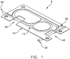
- Disposable cassette 5 which comprises one preferred form of the invention.
- Disposable cassette 5 is adapted for disposition intermediate the fluid line (e.g., an IV line), wherein fluid flowing through the disposable cassette may be monitored and, if a gas bubble (e.g., an air bubble) is detected within the fluid flow, the fluid flow may be stopped and the gas bubble removed before continuing the fluid flow.
- Disposable cassette 5 comprises a body 10 including tubing 15 ( Fig. 1 ).
- Tubing 15 has an inlet port 20, and outlet port 25, and a purge port 30.
- Body 10 and tubing 15 are arranged so that tubing 15 is exposed at a sensor station 35 and at a pinch location 40 (e.g., with openings).
- Inlet port 20 and outlet port 25 are configured with an appropriate fitting (i.e., Luer, male, female, locking "T", stopcock, etc.) so that the tubing 15 of the disposable cassette 5 can be connected intermediate a fluid line entering the patient.
- Purge port 30 provides selective access (e.g., via a removable cap) to the interior of tubing 15, whereby to permit removal of a gas bubble in the fluid line, as will hereinafter be discussed.
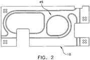
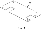
- disposable cassette 5 can be formed by providing a groove 45 in body 10 ( Fig. 2 ), wherein groove 45 is configured to receive tubing 15 ( Fig. 3 ), with a cover 50 ( Fig. 4 ) securing the tubing 15 within groove 45.
- Body 10 and cover 50 are preferably formed out of medical grade, soft or semi-soft, sterilizable, clear or transparent or semi-transparent, plastic such as PVC, a urethane, etc.
- Tubing 15 is preferably a clear plastic FDA Class 6 tubing with a durometer consistent with the "pinch" requirements of the base unit's pinch valve, as will hereinafter be discussed.
- Tubing 15 is sized so as to be consistent with the flow requirements of the IV fluid line.
- a tube 15 having a 1/8 inch inside diameter, and a 3/16 inch outside diameter may be used.
- the disposable cassette 5 is provided to the user in a pre-assembled form (i.e., with tubing 15 loaded into groove 45 and sealed in place with cover 50), with the disposable cassette being sealed in a sterilized package which is opened at the time of use.
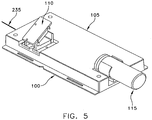
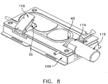
- Base unit 100 which comprises one preferred form of the invention.
- Base unit 100 is adapted to receive disposable cassette 5 and monitor the fluid flow through the disposable cassette and, if a gas bubble is detected, selectively stop the fluid flow through the disposable cassette while the gas bubble is removed.
- Base unit 100 generally comprises a seat 105 ( Fig. 5 ) for seating the disposable cassette 5.
- Base unit 100 also comprises a sensor 110 for detecting the presence of a gas bubble in the fluid flowing through tubing 15 of the disposable cassette.
- sensor 110 comprises an ultrasound sensor ( Fig. 6 ) and, in one particularly preferred form of the invention, sensor 110 comprises an ultrasound sensor having two halves 110A, 110B hinged together at 110C.
- Base unit 100 also comprises a pinch valve 115 ( Fig. 5 ) for selectively pinching off the tubing 15 of disposable cassette 5, whereby to selectively stop fluid flow through the tubing.
- pinch valve 115 may comprise a solenoid having a movable member for (i) engaging the tubing 15 when the movable member is placed into its extended position, whereby to pinch the tubing 15 closed, and (ii) disengaging the tubing 15 when the movable member is placed into its retracted position, whereby to allow the tubing to expand to its full diameter. As seen in Figs.
- disposable cassette 5 and base unit 100 are constructed so that when disposable cassette 5 is received on seat 105, sensor station 35 of disposable cassette 5 is positioned adjacent to sensor 110 of base unit 100, and pinch location 40 of disposable cassette 5 is disposed adjacent to pinch valve 115 of base unit 100.
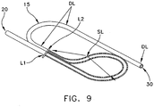
- tubing 15 will pass by sensor 110 at sensor station 35 ( Figs. 7 and 9 ).
- tubing 15 will be monitored by sensor 110 at two locations, L1 and L2.
- the length of tubing 15 extending between the two locations L1 and L2 may be referred to as the "sensor loop" SL.
- a length of tubing extends between sensor location L2 and purge port 30. This length of tubing provides a "delay loop" DL which will hereinafter be discussed.
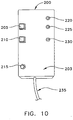
- Electronic control unit 200 which comprises one preferred form of the invention.
- Electronic control unit 200 is adapted to operate base unit 100 as will hereinafter be discussed.
- Electronic control unit 200 generally comprises a housing 203, an on/off switch 205, a sound off switch 210, a system reset switch 215, a green light 220, a system red light 225, a sound red light 230, an umbilical cord 235 for connecting electronic control unit 200 to base unit 100, and various conventional electronic components (not shown) housed by housing 203 and adapted to operate as will hereinafter be discussed.
- umbilical cord 235 connects electronic control unit 200 to the base unit's sensor 110 whereby to operate (i.e., power and read) the same, and umbilical cord 235 connects electronic control unit 200 to the base unit's pinch valve 115, whereby to operate (i.e., power and control) the same.
- Electronic control unit 200 is preferably internally powered by a 12 volt rechargeable battery pack, although it may also be powered by an external power source, e.g., by connection to a wall plug.
- a disposable cassette 5 is withdrawn from its sterilized package and loaded into base unit 100. This is done by opening sensor 110, seating disposable cassette 5 on the base unit's seat 105 so that the cassette's sensor station 35 is located adjacent to the base unit's sensor 110 and so that the disposable cassette's pinch location 40 is located adjacent to the base unit's pinch valve 115, and then closing sensor 110.
- the "source side" of a fluid line (e.g., an IV line) is connected to the cassette's inlet port 20, and the cassette's output port 25 is connected to the "patient side” of the IV line.
- a fluid line e.g., an IV line
- the IV line is then primed, air removed, etc. so that the fluid line is ready to infuse the patient.
- fluid is allowed to flow from the fluid source into tubing 15 of disposable cassette 5.
- sensor 110 monitors the fluid flow, sensing for the presence of a gas bubble. So long as no gas bubble is detected, the fluid is allowed to flow uninterrupted, thereby infusing the patient with the desired fluid.
- Green light 220 is lit when the system is on and no gas bubble is detected by sensor 110.
- electronic control unit 200 turns on red light 225, sounds an audible alarm in electronic control unit 200, and activates pinch valve 115, thereby arresting the fluid flow.
- a gas bubble e.g., an air bubble
- the operator can now activate the sound off switch 210, temporarily turning the alarm sound off, and then use purge port 30 to bleed the gas bubble from the system.
- the sensor no longer detects a gas bubble at sensor station 35, indicating that the gas bubble has been purged from the line, green light 220 comes back on, signifying that the system may now be reset.
- the operator then actuates system reset switch 215, thereby resetting the system.
- pinch valve 115 is re-opened, thereby permitting the fluid flow to resume.
- the electronic control unit 200 then turns the sound alarm back on.
- the disposable cassette's tubing 15 passes by sensor 110 at two locations, i.e., L1 and L2.
- the system can be configured such that sensor 110 and electronic control unit 200 trigger a fault condition when a gas bubble is detected at either location L1 or L2.
- the system is configured such that sensor 110 and electronic control unit 200 trigger a fault condition only when a gas volume is simultaneously detected at both locations L1 and L2.
- This configuration can be advantageous, inasmuch as simultaneously detecting a gas bubble at both locations L1 and L2 can be indicative of the presence of a large gas bubble in the fluid line, i.e., one completely filling the sensor loop SL.
- the system can discriminate between gas bubbles of different sizes, activating the fault condition only when the gas bubble exceeds a certain size.
- the length of the sensor loop SL, and its internal volume determines the amount of gas that can be present in the circuit before the fault condition is triggered.
- This feature can be advantageous, inasmuch as adults may be capable of safely tolerating a larger gas bubble than an infant, etc.
- gas bubbles commonly exist in most IV circuits; tiny gas bubbles are generally deemed harmless, and it is only the larger gas bubbles which are considered to pose a threat to the patient.
- sensor loop SL is configured to have a volume of 1 cc.
- delay loop DL is configured to have a length of 10 cm.
- Disposable cassette 5 is preferably discarded after use.
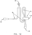
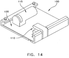
- FIGs. 11-16 there are shown alternative constructions for disposable cassette 5 and base unit 100.
- this form of the invention utilizes (i) a different and more compact geometry than that shown in Figs. 1-10 ; (ii) a one-piece sensor 110; and (iii) a vacuum-formed cassette body 10 which encompasses portions of tubing 15, whereby to eliminate the use of body grooves 45 and cover 50.
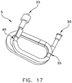
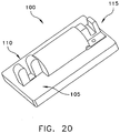
- FIGs. 17-21 there are shown other alternative constructions for disposable cassette 5 and base unit 100.
- this form of the invention utilizes (i) a different and more compact geometry than that shown in Figs. 1-16 ; (ii) a disposable cassette 5 omitting the large planar body 10 and cover 50, with tubing 15 in the form of an inline stacked configuration and secured together (e.g., with glue, molding techniques, etc.) so as to form the structure of disposable cassette 5 (here, the securing structure can be thought of as constituting the body 10); and (iii) a base unit 100 modified to receive the modified disposable cassette 5.
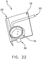
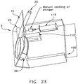
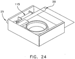
- FIGs. 22-24 there are shown further alternative constructions for disposable cassette 5 and base unit 100.
- this form of the invention utilizes (i) a different and more compact geometry than that shown in Figs. 1-21 ; (ii) a disposable cassette 5 having an L-shaped body 10, with tubing 15 in the form of an inline stacked coil configuration and secured together (e.g., with glue, molding techniques, etc.); and (iii) a base unit 100 utilizing a manually cocked pinch valve 15.
- This manual pinch valve construction can be advantageous in further reducing the size of the pinch valve and hence reducing the size of the base unit 100.
- the system has to be reset manually by compressing the valve's spring-loaded pinch bar until it is cocked in place. Upon the detection of a gas bubble in the sensor loop, the locking mechanism is electronically released.
- Fig. 25 it will be seen that the geometry of the disposable cassette's tubing 15 can be arranged as desired so as to provide the desired sensor loop SL and delay loop DL.
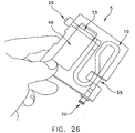
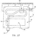
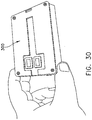
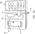
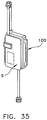
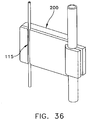
- Figs. 26-34 there is shown still another novel system for detecting and removing a gas bubble from a liquid infusion line.
- the base unit 100 and the electronic control unit 200 are contained in the same housing.
- a detachable battery pack 300 for powering the system.
- the system described above is adapted to stop fluid flow to the patient upon the detection of a gas bubble, and then requires the operator to intervene by manually bleeding the gas bubble out of the line and then resetting the system.
- this intervention is automated in the sense that, upon detection of a gas bubble, the flow of liquid (e.g. IV liquid) is diverted to a collection bag until the sensor 110 once again detects liquid in the IV line.
- the sensor 110 again detects liquid in the IV line, the gas bubble between sensor 110 and the flow diverting mechanism is flushed out of the system before flow is diverted back to the patient.
- liquid e.g. IV liquid
- sensor 110 again detects liquid in the IV line
- the gas bubble between sensor 110 and the flow diverting mechanism is flushed out of the system before flow is diverted back to the patient.
- the diverting mechanism can take many different forms.
- the diverting mechanism can be a disposable Y connector molded into the disposable cartridge 5 and an integral part of the disposable cartridge, with the bottom part of the Y connected to sensor 110, downstream from the liquid delay loop DL of the disposable cartridge 5.
- the second gas bubble sensor is positioned to detect a gas bubble in the central part of the Y.
- a two-sided pinch valve 115 is attached to the two top parts of the Y; this pinch valve has two pinching stations, and is arranged so that when one station is open, the other station is closed.
- a normally open side of pinch valve 115 is positioned at one of the top forks of the Y and the normally closed part of the pinch valve 115 is positioned on the other side of the fork in the top part of the Y.
- Simple activation of the pinch valve 115 now will allow the flow to be diverted from one side of the disposable cartridge Y to the other. The appropriate side will be connected to the patient; the other side is connected to the collection bag.
- a further device configuration would allow for yet a third gas bubble sensor (not shown) to be incorporated in the device.
- the third gas bubble sensor can be a clamp-on sensor to be positioned on the tubing slightly downstream from the IV bag or other fluid source, to detect when the IV bag is empty, to halt the flow or divert it from the patient and then sound an alarm, signaling an empty IV bag.
- means were disclosed for selectively diverting the flow of fluid away from the patient (when the fluid flow contains a gas bubble) and then an automatic resumption of fluid flow to the patient (when the gas bubble has been purged from the line).
- the fluid flow upon detection of a gas bubble, is automatically diverted away from the patient using any of several methods disclosed above or any other suitable means for diverting the gas embolus and maintaining the safety of the patient; but then the fluid flow is not automatically diverted back to the patient but, rather, continues to be directed away from the patient until the attendant resets the device. This will allow the attendant to assess the situation and reset the system when appropriate.
- An alternate electronic method to trigger the pinch valve 115, or to reroute the fluid flow to a collection bag or back to the patient entails the electronic calculation of the time the sensor 110 senses a gas bubble in the tubing.
- an electronic signal signifying "gas” is triggered at the onset of the gas bolus, and the electronic control unit 200 senses the time that the "gas signal" came on.
- the internal cross-sectional area of the tubing 15 is known.
- An automatic calculation is performed as to the gas volume passing through the line. If one sensor is used, the gas volume passing through is calculated using an assumed flow rate. This also allows for the calculation of the velocity of the fluid.
- this allows for the calculation of the pressure drop in the tubing, allowing for a volume adjustment of the gas flowing through.
- This calculation is done in real-time and continuously updates its information and, when a predetermined gas volume is sensed, the system triggers its mode of action (e.g., shuts off, alarms, diverts the flow, etc.).
- the use of two sensors in series, positioned a known distance apart may be utilized.
- the sensor configuration and positioning should follow the basic parameters of the system, allowing sufficient time for action before releasing the fluid to the patient.
Landscapes
- Health & Medical Sciences (AREA)
- Heart & Thoracic Surgery (AREA)
- Vascular Medicine (AREA)
- Engineering & Computer Science (AREA)
- Anesthesiology (AREA)
- Biomedical Technology (AREA)
- Hematology (AREA)
- Life Sciences & Earth Sciences (AREA)
- Animal Behavior & Ethology (AREA)
- General Health & Medical Sciences (AREA)
- Public Health (AREA)
- Veterinary Medicine (AREA)
- Emergency Medicine (AREA)
- Infusion, Injection, And Reservoir Apparatuses (AREA)
Claims (10)
- Système de détection et d'élimination d'une bulle de gaz d'un tube de perfusion vasculaire, le système comprenant :une cassette jetable (5) destinée à être placée entre le tube de fluide, la cassette jetable (5) comprenant :un corps (10) ; etun tube creux souple (15) comportant un orifice d'admission (20) conçu pour le raccordement au côté alimentation du tube de de fluide, un orifice d'évacuation (25) conçu pour le raccordement au côté patient du tube de fluide et un orifice de purge (30) si tué entre l'orifice d'admission (20) et l'orifice d'évacuation (25) ;une unité de base (100) destinée à recevoir la cassette jetable (5) et surveiller un écoulement de fluide à travers le tube creux souple (15), en ce que l'unité de base (100) comprend :un capteur (110) destiné à détecter la présence d'une bulle de gaz dans l'écoulement de fluide à travers le tube creux souple (15) ; etune vanne à manchon (115) destinée à arrêter l'écoulement de fluide à travers le tube creux souple (15) ; etune unité de commande électronique (200) destinée à actionner l'unité de base (100) de façon à ce que (i) du fluide puisse s'écouler par la vanne à manchon (115) lorsqu'aucune bulle de gaz n'est détectée par le capteur (110) ; et (ii) un écoulement de fluide est arrêté lorsqu'une bulle de gaz est détectée par le capteur (110),caractérisé en ce quea) le tube creux souple (15) est disposé selon une configuration de rappel à la position initiale afin de créer une boucle de capteur (SL) de façon à ce que deux parties (L1, L2) soient adjacentes l'une par rapport à l'autre, etb) le capteur (110) est destiné à détecter simultanément la présence d'une bulle de gaz dans l'écoulement de fluide à travers au moins deux parties (L1, L2) du tube creux souple (15).
- Système selon la revendication 1, en ce que le corps (10) de la cassette jetable (5) entoure au moins une partie du tube creux souple (15).
- Système selon la revendication 1, en ce que la cassette jetable (5) comprend un tube creux souple (15) disposé selon une configuration en ligne, et en outre en ce que le corps (10) comprend la structure destinée à stabiliser le tube creux souple (15) selon cette configuration.
- Système selon la revendication 1, en ce que le corps (10) de la cassette jetable (5) comprend une ouverture facilitant le positionnement du tube creux souple (15) adjacent au capteur (110).
- Système selon l'une des revendications précédentes, en ce que- le tube creux (15) est sous forme de passage, et- la vanne à manchon (115) est réalisée en tant que vanne pour arrêter sélectivement un écoulement de fluide à travers le passage et comprend une première et une seconde partie,- en ce que la première partie de ladite vanne pour arrêter sélectivement un écoulement de fluide à travers le passage est constituée de la cassette (5),- pendant que la seconde partie de ladite vanne pour arrêter sélectivement un écoulement de fluide à travers le passage est constituée de l'unité de base (100),- et en ce que l'unité de commande électronique (200) est destinée à actionner la seconde partie de la vanne de façon à ce que (i) du fluide puisse s'écouler par la première partie de la vanne lorsqu'aucune bulle de gaz n'est détectée par le capteur (110) ; et (ii) un écoulement de fluide est arrêté lorsqu'une bulle de gaz est détectée par le capteur (110).
- Système selon l'une des revendications 1 à 4 de détection et d'élimination d'une bulle de gaz d'un tube de perfusion vasculaire en ce que- le tube creux (15) est sous forme de passage, et- l'unité de commande électronique (200) étant disposée de manière adjacente au tube creux (15), en amont de la cassette (5), comprenant la vanne à manchon (115) pour arrêter sélectivement un écoulement de fluide à travers le tube creux, et un circuit pour communiquer avec le capteur (110) et pour le fonctionnement de la vanne (115) de façon à ce que (i) du fluide puisse s'écouler par le tube creux lorsqu'aucune bulle de gaz n'est détectée par le capteur (110) ; et (ii) un écoulement de fluide à travers le tube creux est arrêté lorsqu'une bulle de gaz est détectée par le capteur (110), et- l'orifice de purge (30) est situé en amont du patient et en aval de l'unité de commande électronique (200).
- Procédé de détection et d'élimination d'une bulle de gaz d'un tube de perfusion vasculaire, le procédé consistant à :mettre à disposition un système selon l'une des revendications précédentes, comprenant :une cassette jetable (5) destinée à être placée entre le tube de fluide, la cassette jetable (5) comprenant :un corps (10) ; etun tube creux souple (15) comportant un orifice d'admission (20) conçu pour le raccordement au côté alimentation du tube de fluide, comportant un orifice d'évacuation (25) conçu pour le raccordement au côté patient du tube de fluide, et un orifice de purge (30) situé entre l'orifice d'admission (20) et l'orifice d'évacuation (25) ; le tube creux souple (15) étant disposé selon une configuration de rappel à la position initiale afin de créer une boucle de capteur (SL) de façon à ce que deux parties (L1, L2) soient adjacentes l'une par rapport à l'autre, etune unité de base (100) destinée à recevoir la cassette jetable (5) et surveiller un écoulement de fluide à travers le tube creux souple (15), en ce que l'unité de base (100) comprend :un capteur (110) destiné à détecter simultanément la présence d'une bulle de gaz dans l'écoulement de fluide à travers au moins deux parties (L1, L2) du tube creux souple (15), etune vanne à manchon (115) destinée à arrêter l'écoulement de fluide à travers le tube creux souple (15) ; etune unité de commande électronique (200) destinée à actionner l'unité de base (100) de façon à ce que (i) du fluide puisse s'écouler par la vanne à manchon (115) lorsqu'aucune bulle de gaz n'est détectée par le capteur (110) ; et (ii) un écoulement de fluide est arrêté lorsqu'une bulle de gaz est détectée par le capteur (110) ;initier un écoulement de fluide à travers la cassette jetable (5) ; etsurveiller l'écoulement de fluide à travers la cassette jetable (5) en fonction de la présence d'une bulle de gaz et, si une bulle de gaz est détectée, arrêter l'écoulement de fluide à travers le tube creux souple (15).
- Procédé selon la revendication 7 comportant une autre étape consistant à éliminer une bulle de gaz détectée à travers l'orifice de purge (30).
- Procédé selon l'une des revendications 7 ou 8, en ce que- le tube creux (15) est sous forme d'un passage, et- la vanne à manchon (115) est réalisée en tant que vanne pour arrêter sélectivement un écoulement de fluide à travers le passage et comporte une première et une seconde partie,- en ce que la première partie de ladite vanne pour arrêter sélectivement un écoulement de fluide à travers le passage est constituée de la cassette (5),- pendant que la seconde partie de ladite vanne pour arrêter sélectivement un écoulement de fluide à travers le passage est constituée de l'unité de base (100),- et en ce que l'unité de commande électronique (200) est destinée à actionner la seconde partie de la vanne de façon à ce que (i) du fluide puisse s'écouler par la première partie de la vanne lorsqu'aucune bulle de gaz n'est détectée par le capteur (110) ; et (ii) un écoulement de fluide est arrêté lorsqu'une bulle de gaz est détectée par le capteur (110).
- Procédé selon l'une des revendications 7 ou 8 de détection et d'élimination d'une bulle de gaz d'un tube de perfusion vasculaire en ce que- le tube creux (15) est sous forme d'un passage, et- l'unité de commande électronique (200) est disposée de manière adjacente par rapport au tube creux (15), en amont de la cassette (5), comprenant la vanne à manchon (115) pour arrêter sélectivement un écoulement de fluide à travers le tube creux, et un circuit pour communiquer avec le capteur (110) et pour le fonctionnement de la vanne (115) de façon à ce que (i) du fluide puisse s'écouler par le tube creux lorsqu'aucune bulle de gaz n'est détectée par le capteur (110) ; et (ii) un écoulement de fluide à travers le tube creux est arrêté lorsqu'une bulle de gaz est détectée par le capteur (110), et- l'orifice de purge (30) est situé en amont du patient et en aval de l'unité de commande électronique (200).
Applications Claiming Priority (3)
| Application Number | Priority Date | Filing Date | Title |
|---|---|---|---|
| US57331104P | 2004-05-21 | 2004-05-21 | |
| US63047104P | 2004-11-23 | 2004-11-23 | |
| PCT/US2005/018173 WO2006014200A1 (fr) | 2004-05-21 | 2005-05-23 | Systeme de detection et d'elimination d'une bulle de gaz d'un tube de perfusion vasculaire |
Publications (3)
| Publication Number | Publication Date |
|---|---|
| EP1768719A1 EP1768719A1 (fr) | 2007-04-04 |
| EP1768719A4 EP1768719A4 (fr) | 2012-12-26 |
| EP1768719B1 true EP1768719B1 (fr) | 2019-04-10 |
Family
ID=35787394
Family Applications (1)
| Application Number | Title | Priority Date | Filing Date |
|---|---|---|---|
| EP05757332.1A Expired - Lifetime EP1768719B1 (fr) | 2004-05-21 | 2005-05-23 | Systeme de detection et d'elimination d'une bulle de gaz d'un tube de perfusion vasculaire |
Country Status (5)
| Country | Link |
|---|---|
| US (4) | US7798996B1 (fr) |
| EP (1) | EP1768719B1 (fr) |
| JP (1) | JP5129568B2 (fr) |
| CA (1) | CA2570139C (fr) |
| WO (1) | WO2006014200A1 (fr) |
Families Citing this family (36)
| Publication number | Priority date | Publication date | Assignee | Title |
|---|---|---|---|---|
| US9604014B2 (en) | 2004-05-21 | 2017-03-28 | Clearline Md, Llc | System for detecting and removing a gas bubble from a vascular infusion line |
| JP5129568B2 (ja) * | 2004-05-21 | 2013-01-30 | アニシージア・セイフティ・プロダクツ・エルエルシー | 脈管注入ラインから気泡を検出し、除去するためのシステム |
| CA2677343C (fr) | 2007-02-05 | 2016-06-21 | Boston Scientific Limited | Appareil et procede de thrombectomie |
| JP5347384B2 (ja) * | 2008-08-29 | 2013-11-20 | 株式会社ジェイ・エム・エス | 輸液装置 |
| US9510854B2 (en) | 2008-10-13 | 2016-12-06 | Boston Scientific Scimed, Inc. | Thrombectomy catheter with control box having pressure/vacuum valve for synchronous aspiration and fluid irrigation |
| US8394087B2 (en) * | 2009-09-24 | 2013-03-12 | Vivant Medical, Inc. | Optical detection of interrupted fluid flow to ablation probe |
| US20110184374A1 (en) * | 2010-01-27 | 2011-07-28 | Gao Shawn X | Peristaltic Pump and Cassette |
| EP2372330B1 (fr) * | 2010-03-31 | 2013-01-16 | LIFEBRIDGE Medizintechnik AG | Détecteur de bulles |
| US20140371707A1 (en) * | 2011-01-26 | 2014-12-18 | Sean Y. Sullivan | Method and device for insertion of tubing into irrigation and infusion fluid pumps |
| WO2014036111A1 (fr) * | 2012-08-28 | 2014-03-06 | Anesthesia Safety Products, Llc | Système de détection et d'élimination d'une bulle de gaz d'un tube de perfusion vasculaire |
| PT3092017T (pt) * | 2014-01-10 | 2024-10-22 | Bayer Healthcare Llc | Conetor de conjunto descartável de utilização única |
| US9248221B2 (en) | 2014-04-08 | 2016-02-02 | Incuvate, Llc | Aspiration monitoring system and method |
| US9433427B2 (en) | 2014-04-08 | 2016-09-06 | Incuvate, Llc | Systems and methods for management of thrombosis |
| US9883877B2 (en) | 2014-05-19 | 2018-02-06 | Walk Vascular, Llc | Systems and methods for removal of blood and thrombotic material |
| US10702292B2 (en) | 2015-08-28 | 2020-07-07 | Incuvate, Llc | Aspiration monitoring system and method |
| US10561440B2 (en) | 2015-09-03 | 2020-02-18 | Vesatek, Llc | Systems and methods for manipulating medical devices |
| US20170100142A1 (en) | 2015-10-09 | 2017-04-13 | Incuvate, Llc | Systems and methods for management of thrombosis |
| US10041495B2 (en) * | 2015-12-04 | 2018-08-07 | Clay Valley Holdings Inc. | High volume vacuum pump for continuous operation |
| US10226263B2 (en) | 2015-12-23 | 2019-03-12 | Incuvate, Llc | Aspiration monitoring system and method |
| US10492805B2 (en) | 2016-04-06 | 2019-12-03 | Walk Vascular, Llc | Systems and methods for thrombolysis and delivery of an agent |
| WO2019035415A2 (fr) * | 2017-08-14 | 2019-02-21 | Terumo Kabushiki Kaisha | Cassette de collecte de composant biologique, kit de collecte de composant biologique, système de collecte de composant biologique et procédé de fabrication d'une cassette de collecte de composant biologique |
| US11678905B2 (en) | 2018-07-19 | 2023-06-20 | Walk Vascular, Llc | Systems and methods for removal of blood and thrombotic material |
| JP7607030B2 (ja) | 2019-09-20 | 2024-12-26 | テルモ株式会社 | 生体成分用カセット、生体成分用キット及び生体成分処理システム |
| CN114728159B (zh) | 2019-11-12 | 2025-10-17 | 费森尤斯医疗护理德国有限责任公司 | 血液治疗系统 |
| CN114728117B (zh) | 2019-11-12 | 2025-11-11 | 费森尤斯医疗护理德国有限责任公司 | 血液治疗系统 |
| CA3160871A1 (fr) | 2019-11-12 | 2021-05-20 | Fresenius Medical Care Deutschland Gmbh | Systemes de traitement du sang |
| CA3160967A1 (fr) | 2019-11-12 | 2021-05-20 | Fresenius Medical Care Deutschland Gmbh | Systemes de traitement du sang |
| CA3160952A1 (fr) | 2019-11-12 | 2021-05-20 | Fresenius Medical Care Deutschland Gmbh | Systemes de traitement du sang |
| EP4058094A1 (fr) | 2019-11-12 | 2022-09-21 | Fresenius Medical Care Deutschland GmbH | Systèmes de traitement du sang |
| WO2021119401A1 (fr) | 2019-12-12 | 2021-06-17 | Fresenius Medical Care Holdings, Inc. | Systèmes de traitement du sang |
| WO2021157712A1 (fr) * | 2020-02-06 | 2021-08-12 | Terumo Kabushiki Kaisha | Cassette de trajet d'écoulement, kit de culture cellulaire et système de culture cellulaire |
| WO2022174175A1 (fr) | 2021-02-15 | 2022-08-18 | Walk Vascular, Llc | Systèmes et procédés d'élimination de sang et de matériau thrombotique |
| US12274458B2 (en) | 2021-02-15 | 2025-04-15 | Walk Vascular, Llc | Systems and methods for removal of blood and thrombotic material |
| EP4134122A1 (fr) * | 2021-08-10 | 2023-02-15 | Erbe Elektromedizin GmbH | Instrument d'application de fluide et dispositif de serrage |
| JP2023142153A (ja) * | 2022-03-24 | 2023-10-05 | テルモ株式会社 | 制御装置、制御方法、制御システム及びコンピュータプログラム |
| US12102789B1 (en) * | 2023-03-28 | 2024-10-01 | Jubilant Draximage Inc. | Radiopharmaceutical delivery system and use thereof for patient infusion |
Family Cites Families (10)
| Publication number | Priority date | Publication date | Assignee | Title |
|---|---|---|---|---|
| US5211201A (en) * | 1986-03-04 | 1993-05-18 | Deka Products Limited Partnership | Intravenous fluid delivery system with air elimination |
| US5382232A (en) * | 1992-03-13 | 1995-01-17 | Ivac Corporation | Infusion system with air-in-line clear function |
| US5827219A (en) * | 1993-10-28 | 1998-10-27 | Medrad, Inc. | Injection system and pumping system for use therein |
| US5658133A (en) * | 1994-03-09 | 1997-08-19 | Baxter International Inc. | Pump chamber back pressure dissipation apparatus and method |
| US6142008A (en) * | 1998-06-12 | 2000-11-07 | Abbott Laboratories | Air bubble sensor |
| US6293926B1 (en) * | 1999-11-10 | 2001-09-25 | Alcon Universal Ltd. | Peristaltic pump and cassette |
| US6890291B2 (en) * | 2001-06-25 | 2005-05-10 | Mission Medical, Inc. | Integrated automatic blood collection and processing unit |
| US6932114B2 (en) * | 2002-02-22 | 2005-08-23 | Integrated Sensing Systems, Inc. | Fluid delivery system and method |
| WO2004110524A2 (fr) * | 2003-06-06 | 2004-12-23 | Phacor, Inc. | Cassette d'ecoulement de fluide pour instrument de chirurgie ophtalmique |
| JP5129568B2 (ja) * | 2004-05-21 | 2013-01-30 | アニシージア・セイフティ・プロダクツ・エルエルシー | 脈管注入ラインから気泡を検出し、除去するためのシステム |
-
2005
- 2005-05-23 JP JP2007527560A patent/JP5129568B2/ja not_active Expired - Fee Related
- 2005-05-23 CA CA2570139A patent/CA2570139C/fr not_active Expired - Fee Related
- 2005-05-23 US US11/134,894 patent/US7798996B1/en not_active Expired - Fee Related
- 2005-05-23 EP EP05757332.1A patent/EP1768719B1/fr not_active Expired - Lifetime
- 2005-05-23 WO PCT/US2005/018173 patent/WO2006014200A1/fr not_active Ceased
-
2008
- 2008-08-12 US US12/228,384 patent/US7806863B2/en not_active Expired - Fee Related
- 2008-08-13 US US12/228,504 patent/US7806864B2/en not_active Expired - Fee Related
-
2010
- 2010-09-21 US US12/924,142 patent/US8419709B2/en not_active Expired - Fee Related
Non-Patent Citations (1)
| Title |
|---|
| None * |
Also Published As
| Publication number | Publication date |
|---|---|
| US7798996B1 (en) | 2010-09-21 |
| JP2008543349A (ja) | 2008-12-04 |
| EP1768719A4 (fr) | 2012-12-26 |
| US8419709B2 (en) | 2013-04-16 |
| WO2006014200A1 (fr) | 2006-02-09 |
| CA2570139C (fr) | 2012-04-24 |
| US20090163858A1 (en) | 2009-06-25 |
| US7806864B2 (en) | 2010-10-05 |
| EP1768719A1 (fr) | 2007-04-04 |
| US20090163857A1 (en) | 2009-06-25 |
| CA2570139A1 (fr) | 2006-02-09 |
| US7806863B2 (en) | 2010-10-05 |
| US20110197652A1 (en) | 2011-08-18 |
| JP5129568B2 (ja) | 2013-01-30 |
Similar Documents
| Publication | Publication Date | Title |
|---|---|---|
| EP1768719B1 (fr) | Systeme de detection et d'elimination d'une bulle de gaz d'un tube de perfusion vasculaire | |
| US10646665B2 (en) | System for detecting and removing a gas bubble from a vascular infusion line | |
| EP0621791B1 (fr) | Systeme d'administration intraveineuse de fluide a elimination d'air | |
| CA1232503A (fr) | Systeme de controle des liquides de perfusion iv | |
| US8241409B2 (en) | Bubble trap for high flow rate infusion | |
| US5713865A (en) | Intravenous-line air-elimination system | |
| EP0923394B1 (fr) | Pompe pourvue d'un systeme de detection d'erreur pour un dispositif de nutrition clinique | |
| JPH0260661A (ja) | パルス式液体注入装置 | |
| CN102215889A (zh) | 用于识别血管周出血的方法和设备 | |
| EP2890436B1 (fr) | Système de détection et d'élimination d'une bulle de gaz d'un tube de perfusion vasculaire | |
| TW201620561A (zh) | 給藥機構、給藥機構之使用方法、給藥機構用幫浦單元 | |
| JPH059110B2 (fr) |
Legal Events
| Date | Code | Title | Description |
|---|---|---|---|
| PUAI | Public reference made under article 153(3) epc to a published international application that has entered the european phase |
Free format text: ORIGINAL CODE: 0009012 |
|
| 17P | Request for examination filed |
Effective date: 20061215 |
|
| AK | Designated contracting states |
Kind code of ref document: A1 Designated state(s): AT BE BG CH CY CZ DE DK EE ES FI FR GB GR HU IE IS IT LI LT LU MC NL PL PT RO SE SI SK TR |
|
| DAX | Request for extension of the european patent (deleted) | ||
| A4 | Supplementary search report drawn up and despatched |
Effective date: 20121126 |
|
| RIC1 | Information provided on ipc code assigned before grant |
Ipc: A61M 1/00 20060101AFI20121120BHEP Ipc: A61M 5/36 20060101ALI20121120BHEP Ipc: A61M 5/168 20060101ALI20121120BHEP |
|
| 17Q | First examination report despatched |
Effective date: 20140424 |
|
| STAA | Information on the status of an ep patent application or granted ep patent |
Free format text: STATUS: EXAMINATION IS IN PROGRESS |
|
| GRAP | Despatch of communication of intention to grant a patent |
Free format text: ORIGINAL CODE: EPIDOSNIGR1 |
|
| STAA | Information on the status of an ep patent application or granted ep patent |
Free format text: STATUS: GRANT OF PATENT IS INTENDED |
|
| INTG | Intention to grant announced |
Effective date: 20181009 |
|
| GRAS | Grant fee paid |
Free format text: ORIGINAL CODE: EPIDOSNIGR3 |
|
| GRAA | (expected) grant |
Free format text: ORIGINAL CODE: 0009210 |
|
| STAA | Information on the status of an ep patent application or granted ep patent |
Free format text: STATUS: THE PATENT HAS BEEN GRANTED |
|
| AK | Designated contracting states |
Kind code of ref document: B1 Designated state(s): AT BE BG CH CY CZ DE DK EE ES FI FR GB GR HU IE IS IT LI LT LU MC NL PL PT RO SE SI SK TR |
|
| REG | Reference to a national code |
Ref country code: GB Ref legal event code: FG4D |
|
| REG | Reference to a national code |
Ref country code: CH Ref legal event code: EP Ref country code: AT Ref legal event code: REF Ref document number: 1117817 Country of ref document: AT Kind code of ref document: T Effective date: 20190415 |
|
| REG | Reference to a national code |
Ref country code: IE Ref legal event code: FG4D |
|
| REG | Reference to a national code |
Ref country code: DE Ref legal event code: R096 Ref document number: 602005055636 Country of ref document: DE |
|
| REG | Reference to a national code |
Ref country code: NL Ref legal event code: MP Effective date: 20190410 |
|
| REG | Reference to a national code |
Ref country code: LT Ref legal event code: MG4D |
|
| REG | Reference to a national code |
Ref country code: AT Ref legal event code: MK05 Ref document number: 1117817 Country of ref document: AT Kind code of ref document: T Effective date: 20190410 |
|
| PG25 | Lapsed in a contracting state [announced via postgrant information from national office to epo] |
Ref country code: NL Free format text: LAPSE BECAUSE OF FAILURE TO SUBMIT A TRANSLATION OF THE DESCRIPTION OR TO PAY THE FEE WITHIN THE PRESCRIBED TIME-LIMIT Effective date: 20190410 |
|
| PG25 | Lapsed in a contracting state [announced via postgrant information from national office to epo] |
Ref country code: ES Free format text: LAPSE BECAUSE OF FAILURE TO SUBMIT A TRANSLATION OF THE DESCRIPTION OR TO PAY THE FEE WITHIN THE PRESCRIBED TIME-LIMIT Effective date: 20190410 Ref country code: LT Free format text: LAPSE BECAUSE OF FAILURE TO SUBMIT A TRANSLATION OF THE DESCRIPTION OR TO PAY THE FEE WITHIN THE PRESCRIBED TIME-LIMIT Effective date: 20190410 Ref country code: FI Free format text: LAPSE BECAUSE OF FAILURE TO SUBMIT A TRANSLATION OF THE DESCRIPTION OR TO PAY THE FEE WITHIN THE PRESCRIBED TIME-LIMIT Effective date: 20190410 Ref country code: SE Free format text: LAPSE BECAUSE OF FAILURE TO SUBMIT A TRANSLATION OF THE DESCRIPTION OR TO PAY THE FEE WITHIN THE PRESCRIBED TIME-LIMIT Effective date: 20190410 Ref country code: PT Free format text: LAPSE BECAUSE OF FAILURE TO SUBMIT A TRANSLATION OF THE DESCRIPTION OR TO PAY THE FEE WITHIN THE PRESCRIBED TIME-LIMIT Effective date: 20190910 |
|
| PGFP | Annual fee paid to national office [announced via postgrant information from national office to epo] |
Ref country code: ES Payment date: 20190701 Year of fee payment: 15 |
|
| PG25 | Lapsed in a contracting state [announced via postgrant information from national office to epo] |
Ref country code: PL Free format text: LAPSE BECAUSE OF FAILURE TO SUBMIT A TRANSLATION OF THE DESCRIPTION OR TO PAY THE FEE WITHIN THE PRESCRIBED TIME-LIMIT Effective date: 20190410 Ref country code: GR Free format text: LAPSE BECAUSE OF FAILURE TO SUBMIT A TRANSLATION OF THE DESCRIPTION OR TO PAY THE FEE WITHIN THE PRESCRIBED TIME-LIMIT Effective date: 20190711 Ref country code: BG Free format text: LAPSE BECAUSE OF FAILURE TO SUBMIT A TRANSLATION OF THE DESCRIPTION OR TO PAY THE FEE WITHIN THE PRESCRIBED TIME-LIMIT Effective date: 20190710 |
|
| REG | Reference to a national code |
Ref country code: CH Ref legal event code: PL |
|
| PG25 | Lapsed in a contracting state [announced via postgrant information from national office to epo] |
Ref country code: AT Free format text: LAPSE BECAUSE OF FAILURE TO SUBMIT A TRANSLATION OF THE DESCRIPTION OR TO PAY THE FEE WITHIN THE PRESCRIBED TIME-LIMIT Effective date: 20190410 Ref country code: IS Free format text: LAPSE BECAUSE OF FAILURE TO SUBMIT A TRANSLATION OF THE DESCRIPTION OR TO PAY THE FEE WITHIN THE PRESCRIBED TIME-LIMIT Effective date: 20190810 |
|
| REG | Reference to a national code |
Ref country code: DE Ref legal event code: R097 Ref document number: 602005055636 Country of ref document: DE |
|
| PG25 | Lapsed in a contracting state [announced via postgrant information from national office to epo] |
Ref country code: MC Free format text: LAPSE BECAUSE OF FAILURE TO SUBMIT A TRANSLATION OF THE DESCRIPTION OR TO PAY THE FEE WITHIN THE PRESCRIBED TIME-LIMIT Effective date: 20190410 Ref country code: CZ Free format text: LAPSE BECAUSE OF FAILURE TO SUBMIT A TRANSLATION OF THE DESCRIPTION OR TO PAY THE FEE WITHIN THE PRESCRIBED TIME-LIMIT Effective date: 20190410 Ref country code: CH Free format text: LAPSE BECAUSE OF NON-PAYMENT OF DUE FEES Effective date: 20190531 Ref country code: SK Free format text: LAPSE BECAUSE OF FAILURE TO SUBMIT A TRANSLATION OF THE DESCRIPTION OR TO PAY THE FEE WITHIN THE PRESCRIBED TIME-LIMIT Effective date: 20190410 Ref country code: RO Free format text: LAPSE BECAUSE OF FAILURE TO SUBMIT A TRANSLATION OF THE DESCRIPTION OR TO PAY THE FEE WITHIN THE PRESCRIBED TIME-LIMIT Effective date: 20190410 Ref country code: LI Free format text: LAPSE BECAUSE OF NON-PAYMENT OF DUE FEES Effective date: 20190531 Ref country code: EE Free format text: LAPSE BECAUSE OF FAILURE TO SUBMIT A TRANSLATION OF THE DESCRIPTION OR TO PAY THE FEE WITHIN THE PRESCRIBED TIME-LIMIT Effective date: 20190410 Ref country code: DK Free format text: LAPSE BECAUSE OF FAILURE TO SUBMIT A TRANSLATION OF THE DESCRIPTION OR TO PAY THE FEE WITHIN THE PRESCRIBED TIME-LIMIT Effective date: 20190410 |
|
| REG | Reference to a national code |
Ref country code: BE Ref legal event code: MM Effective date: 20190531 |
|
| PLBE | No opposition filed within time limit |
Free format text: ORIGINAL CODE: 0009261 |
|
| STAA | Information on the status of an ep patent application or granted ep patent |
Free format text: STATUS: NO OPPOSITION FILED WITHIN TIME LIMIT |
|
| PG25 | Lapsed in a contracting state [announced via postgrant information from national office to epo] |
Ref country code: LU Free format text: LAPSE BECAUSE OF NON-PAYMENT OF DUE FEES Effective date: 20190523 |
|
| 26N | No opposition filed |
Effective date: 20200113 |
|
| PG25 | Lapsed in a contracting state [announced via postgrant information from national office to epo] |
Ref country code: TR Free format text: LAPSE BECAUSE OF FAILURE TO SUBMIT A TRANSLATION OF THE DESCRIPTION OR TO PAY THE FEE WITHIN THE PRESCRIBED TIME-LIMIT Effective date: 20190410 |
|
| PG25 | Lapsed in a contracting state [announced via postgrant information from national office to epo] |
Ref country code: IE Free format text: LAPSE BECAUSE OF NON-PAYMENT OF DUE FEES Effective date: 20190523 |
|
| PG25 | Lapsed in a contracting state [announced via postgrant information from national office to epo] |
Ref country code: BE Free format text: LAPSE BECAUSE OF NON-PAYMENT OF DUE FEES Effective date: 20190531 Ref country code: SI Free format text: LAPSE BECAUSE OF FAILURE TO SUBMIT A TRANSLATION OF THE DESCRIPTION OR TO PAY THE FEE WITHIN THE PRESCRIBED TIME-LIMIT Effective date: 20190410 |
|
| PG25 | Lapsed in a contracting state [announced via postgrant information from national office to epo] |
Ref country code: CY Free format text: LAPSE BECAUSE OF FAILURE TO SUBMIT A TRANSLATION OF THE DESCRIPTION OR TO PAY THE FEE WITHIN THE PRESCRIBED TIME-LIMIT Effective date: 20190410 |
|
| PG25 | Lapsed in a contracting state [announced via postgrant information from national office to epo] |
Ref country code: HU Free format text: LAPSE BECAUSE OF FAILURE TO SUBMIT A TRANSLATION OF THE DESCRIPTION OR TO PAY THE FEE WITHIN THE PRESCRIBED TIME-LIMIT; INVALID AB INITIO Effective date: 20050523 |
|
| PGFP | Annual fee paid to national office [announced via postgrant information from national office to epo] |
Ref country code: FR Payment date: 20210531 Year of fee payment: 17 |
|
| PGFP | Annual fee paid to national office [announced via postgrant information from national office to epo] |
Ref country code: GB Payment date: 20210531 Year of fee payment: 17 |
|
| PG25 | Lapsed in a contracting state [announced via postgrant information from national office to epo] |
Ref country code: IT Free format text: LAPSE BECAUSE OF NON-PAYMENT OF DUE FEES Effective date: 20200523 |
|
| PGFP | Annual fee paid to national office [announced via postgrant information from national office to epo] |
Ref country code: DE Payment date: 20210729 Year of fee payment: 17 |
|
| REG | Reference to a national code |
Ref country code: DE Ref legal event code: R119 Ref document number: 602005055636 Country of ref document: DE |
|
| GBPC | Gb: european patent ceased through non-payment of renewal fee |
Effective date: 20220523 |
|
| PG25 | Lapsed in a contracting state [announced via postgrant information from national office to epo] |
Ref country code: FR Free format text: LAPSE BECAUSE OF NON-PAYMENT OF DUE FEES Effective date: 20220531 |
|
| PG25 | Lapsed in a contracting state [announced via postgrant information from national office to epo] |
Ref country code: GB Free format text: LAPSE BECAUSE OF NON-PAYMENT OF DUE FEES Effective date: 20220523 Ref country code: DE Free format text: LAPSE BECAUSE OF NON-PAYMENT OF DUE FEES Effective date: 20221201 |